cc/td/doc/product/ong/15216/216oadm
hometocprevnextglossaryfeedbacksearchhelp
PDF

Table Of Contents

Installing the Cisco ONS 15216 OADMs

1.1 Overview

1.2 OADM Description

1.2.1 Functional Description

1.2.2 Physical Description

1.3 Installation

1.4 Adding Wavelengths

1.5 Fiber-Optic Connector Cleaning and Maintenance

1.5.1 Customer-Supplied Cleaning Materials

1.6 Fiber Optic Cable Installation

1.7 Specifications


Installing the Cisco ONS 15216 OADMs


1.1 Overview

This document describes and explains how to install Cisco ONS 15216 Optical Add/Drop Multiplexers (OADMs). There are three separate ONS 15216 OADM rack-mounted assemblies: a one-channel, a two-channel, and a four-channel OADM. The One-Channel and Two-Channel OADMs mount in a 19- or 23-inch rack and occupy 1 rack unit (RU). The Four-Channel OADMs mount in a 19- or 23-inch rack and occupy 2 RU. You can use the ONS 15216 OADMs with the ONS 15454 DWDM ITU optics cards. You can use the OADMs with other optical equipment if the equipment has laser outputs that follow the ITU 100-GHz optics specification.

Insert the OADMs between hub nodes in an amplified optical network in order to add or drop a given number of wavelengths without inducing gain competition between wavelengths during amplification. Each OADM has an electronically variable optical attenuator (EVOA) that is used to set the optical power of the added channel to a user-defined value.

1.2 OADM Description

This section provides functional and physical descriptions of the ONS 15216 OADMs.

1.2.1 Functional Description

Each ONS 15216 OADM consists of two 100-GHz, unidirectional, optical add/drop multiplexer modules that transmit in opposite directions (designated as east and west) in the 1530.33- to 1560.61-nm wavelength range. Each OADM module has an EVOA for every wavelength. The EVOAs are software-controlled using TL1 commands.

The ONS 15216 OADMs have the following ports:

The WEST IN port connects to the incoming (west) fiber.

The WEST OUT port connects to the outgoing (west) fiber.

The EAST IN port connects to the incoming (east) fiber.

The EAST OUT port connects to the outgoing (east) fiber.

The WEST MONITOR OUT port connects to monitoring equipment using a two percent tap coupler and monitors the output signal in the west direction.

The EAST MONITOR OUT port connects to monitoring equipment using a two percent tap coupler and monitors the output signal in the east direction.

The WEST-1 and WEST-2 DROP ports connect to the wavelengths being dropped in the west direction.

The EAST-1 and EAST-2 DROP ports connect to the wavelengths being dropped in the east direction.

The WEST-1 and WEST-2 ADD ports connect to the wavelengths being added in the west direction.

The EAST-1 and EAST-2 ADD ports connect to the wavelengths being added in the east direction.

The ONS 15216 OADMs have an EVOA for every wavelength being added. The EVOA allows you to set the optical power of the added channel to be the same as that of the dropped channel within a certain level of tolerance. Access the OADM via an EIA-TIA 232 (RS-232) interface to initiate a TL1 session. The OADM also provides TL1 over a TCP/IP interface for turn-up, monitoring, and alarm reporting. For a list of TL1 commands, see "TL1 Overview."

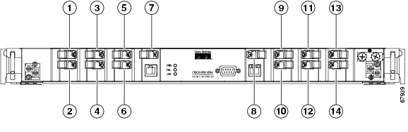
Figure 1-1 shows the faceplate of the Cisco ONS 15216 One-Channel OADM.

Figure 1-1 Cisco ONS 15216 One-Channel OADM front panel

1

Not Used

8

West Monitor Out port

2

Not Used

9

West Out port

3

West In port

10

West-1 Add port

4

West-1 Drop port

11

East In port

5

East Out port

12

East-1 Drop port

6

East-1 Add port

13

Not Used

7

East Monitor Out port

14

Not Used


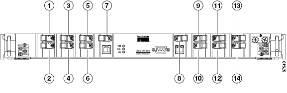
Figure 1-2 shows the faceplate of the Cisco ONS 15216 Two-Channel OADM.

Figure 1-2 Cisco ONS 15216 Two-Channel OADM front panel

1

West In port

8

West Monitor Out port

2

West Drop-2 port

9

West Out port

3

West Drop-1 port

10

West-2 Add port

4

East-1 Add port

11

East-1 Drop port

5

East Out port

12

West-1 Add port

6

East-2 Add port

13

East In port

7

East Monitor Out port

14

East Drop-2 port


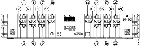
Figure 1-3 shows the faceplate of the Cisco ONS 15216 Four-Channel OADM.


Note On all ONS 15216 OADMs, the ports are numbered in vertical columns beginning in the upper left corner and ending in the lower right corner.


Figure 1-3 Cisco ONS 15216 Four-Channel OADM front panel

1

West In port

12

West Out port

2

West Drop-1 port

13

West Monitor Out

3

West Drop-2 port

14

West Add-2 port

4

East Add-1 port

15

West Add-3 port

5

West Drop-3 port

16

West Add-4 port

6

West Drop-4 port

17

West Add-1 port

7

East Add-2 port

18

East Drop-3 port

8

East Add-3 port

19

East Drop-4 port

9

East Add-4 port

20

East In port

10

East Out port

21

East Drop-1 port

11

East Monitor Out

22

East Drop-2 port


1.2.2 Physical Description

The connectors on all of the OADMs are SC bulkhead adapters. As you face the OADMs, the group of connectors on the left-hand side are the west connectors and the group of connectors on the right-hand side are the east connectors. The connectors are labeled with the corresponding wavelength or function. A retractable tray located under the front panel contains a port map to help you identify port locations. For a complete list of ONS 15216 OADM specifications, see the "Specifications" section.

1.3 Installation

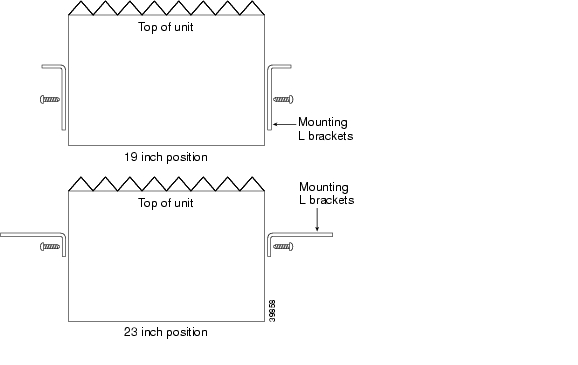
You can install the ONS 15216 OADMs in standard 19- or 23-inch equipment racks. Each OADM assembly includes reversible mounting brackets that you can rotate to fit either rack size. The units ship with the mounting brackets in the 19-inch position. Figure 1-4 shows the top view of a unit with the mounting brackets in both positions.


Warning The ONS 15216 OADMs are intended for installation in restricted access areas. A restricted access area is where access can only be gained by service personnel through the use of a special tool, lock, key, or other means of security. A restricted access area is controlled by the authority responsible for the location


Warning The ONS 15216 OADMs rely on the protective devices in the building installation to protect against short circuit, overcurrent, and grounding faults. Ensure that the protective devices include a listed DC branch circuit breaker of 5A (minimum 60VDC) and that they comply with national and local codes.


Warning Incorporate a readily-accessible, two-poled disconnect device in the fixed wiring.


Warning Install the ONS 15216 OADMs in accordance with the following local and national electrical codes: National Fire Protection Association (NFPA) 70; United States National Electrical Code.


Figure 1-4 Reversible mounting brackets

Procedure: Install the ONS 15216 OADM


Step 1 Set the mounting brackets to either the 19- or 23-inch position, depending on the rack you are using.

The units are shipped with the mounting brackets in the 19-inch position. See Figure 1-4 for mounting bracket position information.

Step 2 Secure the unit to the rack using four mounting screws.

Step 3 Connect the WEST and EAST IN/OUT fibers to/from the outside plant optical patch panel.

Step 4 Connect fibers to the ADD and DROP ports.

When connecting the add/drop ports to the ONS 15454 ITU cards, make sure to connect the east side ports on the OADM to the appropriate ITU card on the east side of the ONS 15454 shelf assembly and the west side ports to the west side of the ONS 15454. Connecting in this manner ensures proper routing to working and protect ITU cards. In unprotected configurations, use each side of the OADM to add and drop wavelengths coming from different working ITU cards.

Step 5 Connect monitoring equipment to the MONITOR ports.

Cisco highly recommends using monitoring equipment. A spectrum analyzer such as the ONS 15216 Optical Performance Manager (OPM) measures signal strength on added wavelengths. The ONS 15216 OPM measures power, frequency, and optical signal to noise ratio (OSNR).

Step 6 Route the cables out through the fiber lockers on each side of the ONS 15216 OADM.

Step 7 Connect a frame ground wire to the unit via the chassis ground connector on the right side panel of the OADM before connecting the DC power.

The crimping tool must be large enough to accommodate #10-14 AWG stranded wire or #10-12 AWG solid wire. (An example of an approved tool is the SPC Technology type CTT-8420-01 crimper which will accomodate #10-22 AWG wire.)

Step 8 Verify that the unit is properly fused using a 5A fuse in the fuse and alarm panel.

Step 9 Using a pair of #22 AWG wires, connect the battery source to the terminals on the front panel. Connect two -48 VDC sources (A and B) to ensure uninterrupted operation during a power failure or disconnection to the primary power source.

Step 10 Connect the office alarm.

Office alarm pinouts are:

First pair: loss of both A and B DC power feeds

Second pair: general unit failure

Third pair: loss of signal

Fourth pair: loss of A or B DC power feed

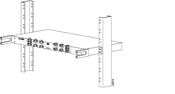
Figure 1-5 shows an ONS 15216 OADM installed in a rack

Figure 1-5 An ONS 15216 OADM installed in a rack


1.4 Adding Wavelengths

Adding wavelengths to the ONS 15216 OADMs requires that you match the ONS 15454 ITU optical card wavelength to the wavelength of the add port. Add channel power can then be set to a user-defined level via the EVOA.

To balance the optical power, the firmware measures incoming (drop) signal power after the power has been split from the pass-through signals and then allows the user to attenuate the power of the outgoing (add) channel to match. The result is equalized power at any given point on the network. Having equalized power throughout the network reduces both the amount of planning required and the amount of work for field technicians.

1.5 Fiber-Optic Connector Cleaning and Maintenance

Disciplined connector cleaning care is required to maintain the performance of fiber-optic circuits. Both the connector at the end of the fiber-optic cable and the mating bulkhead adapter on the front panel of the ONS 15216 must be clean before you make the connection.


Warning To prevent serious eye damage, never look directly into a fiber optic cable connector or mating adapter. Never assume that the laser power is turned off or the fiber is disconnected at the other end.


Warning Always handle, use, and dispose of chemicals and other cleaning materials in accordance with manufacturer's instructions.


Before installing the fiber-optic cable, always perform the cleaning procedure for cable connectors described in the following section. Whenever possible, inspect each connector before connecting it to the mating bulkhead adapter on the ONS 15216 OADM front panel.

The SC bulkhead adapters on the ONS 15216 OADM front panel are less likely to become dirty if you cap them when not in use. Because the procedure for a thorough cleaning of these adapters is complicated and involves opening the ONS 15216 unit, Cisco recommends that you use a commercially available cleaning kit and closely follow the instructions included with the kit. The following procedures describe only a simple, routine cleaning procedure for these adapters that can be easily performed by the customer.

1.5.1 Customer-Supplied Cleaning Materials

Cisco recommends the following materials. These materials are not supplied with the ONS 15216 module:

Reagent-grade isopropyl alcohol in an alcohol dispenser

Lint-free laboratory wipes

Clean, dry, oil-free compressed air

When cleaning a paired cable connector (bulkhead mating adapter), always clean the mating adapter first. If properly maintained—only used with clean, defect-free fiber connectors and capped when not in use—the mating adapter should not require cleaning. However, if you suspect the adapter is dirty, clean it by blowing with clean, dry, oil-free compressed air.

Procedure: Clean the Bulkhead Mating Adapters


Step 1 Read the manufacturer's instructions to properly use the compressed air can.

Using the compressed air can improperly can contaminate the part being cleaned and defeat the purpose of cleaning the bulkhead mating adapters.

Step 2 Before blowing the adapter clean, release a short blast of compressed air to remove any dust inside the nozzle of the compressed air can.

Step 3 Blow three to four short blasts of air into the adapter housing to remove any dust.


Note Always keep unused adapter ports and fiber connectors capped with a clean dust cap.


Procedure: Clean Fiber-Optic Cable Connectors


Step 1 Fold a clean wipe several times to make a pad of 6 to 8 layers of material.

Step 2 Remove the protective cap on the SC/UPC optical-fiber cable connector.

Step 3 Dampen (but do not soak) a corner of the pad with alcohol using the alcohol dispenser.

Step 4 Firmly press the tip of the ferrule into the alcohol-moistened area of the wipe.

Step 5 Pinch the wipe firmly with your fingers against the ferrule and twist the ferrule.

Repeat this step three times, using a clean, alcohol-moistened area each time to wipe the ferrule.


Note The design of the SC connector makes it difficult to clean the entire perimeter of the ferrule, because only a small portion close to the ferrule tip is accessible. Clean the tip of the ferrule and the entire accessible perimeter. Keep the fiber connector capped at all times when not in use.


Step 6 To dry the ferrule, press the ferrule tip into a clean, dry spot on the wipe and perform the pinch-and-twist procedure described in Step 5 once.

Step 7 Discard the used wipe.

Step 8 (Optional) Use a couple of short blasts of clean, dry, oil-free compressed air to remove any tissue fragments that may have deposited on the ferrule during cleaning.

Step 9 Whenever possible, inspect the ferrule end face to ensure that the cleaning procedure effectively removed the dust/dirt from the ferrule and that cleaning-induced damages are not present.

Step 10 If the ferrule end face is still dirty, repeat Steps 1-8.

Step 11 If the ferrule shows damage (for example, scratches or pits across the fiber core), replace the fiber patch cord with a new one equipped with a defect-free connector.

Defects on the fiber-cable connector are likely to damage the mating connector inside the ONS 15216 OADM, which results in more costly repairs.

Step 12 If the ferrule end face is clean and damage-free, place the connector into the corresponding clean mating adapter on the ONS 15216 OADM front panel following the instructions in the next section.


1.6 Fiber Optic Cable Installation


Warning Follow all directions and warning labels when working with optical fiber cables and adapters. To prevent serious eye damage, never look directly into an optical fiber cable connector or mating adapter.


Warning When connecting an optical fiber patch cord between the ONS 15216 and the optical card ports in the ONS 15454, use the ESD wristband supplied with the ONS 15454. Plug the wristband into the ESD jack on the lower right front corner of the ONS 15454.


Caution Always clean all fiber connectors thoroughly before making the connection with the mating adapter. Very small particles can permanently damage the end of the mating fiber inside the ONS 15216 which makes regular cleaning imperative. See the "Fiber-Optic Connector Cleaning and Maintenance" section for cleaning instructions.


Note The ONS 15216 OADM front panel has SC/UPC bulkhead adapters. Always use fiber-optic cables equipped with the corresponding (SC/UPC) connector type. Using any other type of connector causes damage to the connector and/or adapter.


Procedure: Install and Route Fiber-Optic Cables in the ONS 15216


Step 1 Place the SC/UPC cable connector in front of the corresponding bulkhead adapter on the front panel of the ONS 15216.

Step 2 Align the keyed ridge of the cable connector with the slot in the receiving adapter.

Step 3 Gently push the cable connector into the adapter until you hear a click, indicating that the latching system is engaged.

Step 4 Open the fiber guide by pulling the fiber guide locker on the appropriate side of the front panel.

A spring-ball screw allows you to open or close the fiber guide locker and secures the top of the locker.

Step 5 Route fiber cables through the fiber guide and lock them into place using the fiber guide locker.


1.7 Specifications

ITU Channel Plan

Table 1-1 lists model numbers and wavelengths for the One-Channel OADM (Model 15216-AD1-2A-xx).

Table 1-1 ONS 15216 One-Channel OADM Model Numbers and Wavelengths 

Model Number
Wavelength

15216-AD1-2A-60.6

1560.61 nm

15216-AD1-2A-59.7

1559.79 nm

15216-AD1-2A-58.9

1558.98 nm

15216-AD1-2A-58.1

1558.17 nm

15216-AD1-2A-56.5

1556.55 nm

15216-AD1-2A-55.7

1555.75 nm

15216-AD1-2A-54.9

1554.94 nm

15216-AD1-2A-54.1

1554.13 nm

15216-AD1-2A-52.5

1552.52 nm

15216-AD1-2A-51.7

1551.72 nm

15216-AD1-2A-50.9

1550.92 nm

15216-AD1-2A-50.1

1550.12 nm

15216-AD1-2A-48.5

1548.51 nm

15216-AD1-2A-47.7

1547.72 nm

15216-AD1-2A-46.9

1546.92 nm

15216-AD1-2A-46.1

1546.12 nm

15216-AD1-2A-44.5

1544.53 nm

15216-AD1-2A-43.7

1543.73 nm

15216-AD1-2A-42.9

1542.94 nm

15216-AD1-2A-42.1

1542.14 nm

15216-AD1-2A-40.5

1540.56 nm

15216-AD1-2A-39.7

1539.77 nm

15216-AD1-2A-38.9

1538.98 nm

15216-AD1-2A-38.1

1538.19 nm

15216-AD1-2A-36.6

1536.61 nm

15216-AD1-2A-35.8

1535.82 nm

15216-AD1-2A-35.0

1535.04 nm

15216-AD1-2A-34.2

1534.25 nm

15216-AD1-2A-32.6

1532.68 nm

15216-AD1-2A-31.9

1531.90 nm

15216-AD1-2A-31.1

1531.12 nm

15216-AD1-2A-30.3

1530.33 nm


Table 1-2 lists model numbers and wavelengths for the two-channel OADM (Model 15216-AD2A-2-xx).

Table 1-2  ONS 15216 Two-Channel OADM Model Numbers and Wavelengths

Model Number
Wavelengths

15216-AD2-2A-60.6

1560.61 nm/1559.79 nm

15216-AD2-2A-58.9

1558.98 nm/1558.17 nm

15216-AD2-2A-56.6

1556.66 nm/1555.75 nm

15216-AD2-2A-54.9

1554.94 nm/1554.13 nm

15216-AD2-2A-52.5

1552.52 nm/1551.72 nm

15216-AD2-2A-50.9

1550.92 nm/1550.12 nm

15216-AD2-2A-48.5

1548.51 nm/1547.72 nm

15216-AD2-2A-46.9

1546.92 nm/1546.12 nm

15216-AD2-2A-44.5

1544.53 nm/1543.73 nm

15216-AD2-2A-42.9

1542.94 nm/1542.14 nm

15216-AD2-2A-46.5

1546.56 nm/1539.77 nm

15216-AD2-2A-38.9

1538.98 nm/1538.19 nm

15216-AD2-2A-36.6

1536.61 nm/1535.82 nm

15216-AD2-2A-35.0

1535.04 nm/1534.25 nm

15216-AD2-2A-32.6

1532.68 nm/1531.90 nm

15216-AD2-2A-31.1

1531.12 nm/1530.33 nm


Table 1-3 shows model numbers and wavelengths for the four-channel OADM (Model 15216-AD2A-4-xx).

Table 1-3 ONS 15216 Four-Channel OADM Model Numbers and Wavelengths

Model Number
Wavelengths

15216-AD4-2A-60.6

1560.61 nm/1559.79 nm/1558.98 nm/1558.17 nm

15216-AD4-2A-56.6

1556.66 nm/1555.75 nm/1554.94 nm/1554.13 nm

15216-AD4-2A-52.5

1552.52 nm/1551.72 nm/1550.92 nm/1550.12 nm

15216-AD4-2A-48.5

1548.51 nm/1547.72 nm/1546.92 nm/1546.12 nm

15216-AD4-2A-44.5

1544.53 nm/1543.73 nm/1542.94 nm/1542.14 nm

15216-AD4-2A-46.5

1546.56 nm/1539.77 nm/1538.98 nm/1538.19 nm

15216-AD4-2A-36.6

1536.61 nm/1535.82 nm/1535.04 nm/1534.25 nm

15216-AD4-2A-32.6

1532.68 nm/1531.90 nm/1531.12 nm/1530.33 nm


Channel Spacing

100 GHz

Insertion Loss (Maximum)

One-Channel OADM

-1.6 db pass through

-2.2 db drop

-3.2 db add

Two-Channel OADM

-2.0 db pass through

-2.5 db drop

-3.5 db add

Four-Channel OADM

-1.5 db pass through

-3.6 db drop

-4.5 db add

Input Power Range (each channel)

32 dB: from +3 dBm to -29 dBm

Output Power Range (each added channel)

32 dB: from +3 dBm to -29 dBm

Add Channel Power Range

+4 dBm to -9 dBm

Attenuation Resolution

0.2 dB

Accuracy

1.0 dB

Response Time (for 10-dB change)

100 ms Typical

Add-Out Insertion Loss when electrical power fails

> 20 dB

Power Supply

Dual -48 VDC

Alarms (Loss of Power, LOS, Failure)

Via relay output and TL1 autonomous messages

Interface

RS-232, TL-1 over TCP/IP

Power Consumption

- One-Channel OADM: 6 W typical; 7W maximum

- Two-Channel OADM: 7 W typical; 9W maximum

- Four-Channel OADM: 10 W typical; 13W maximum

Directivity

45 dB minimum

Optical Return Loss

40 dB minimum

Polarization Mode Dispersion

0.1 ps typical

Isolation of Dropped Wavelengths

Adjacent: 25 dB minimum

Non-adjacent: 40 dB minimum

In-out Isolation at Dropped Wavelengths

25 dB

Wavelength Passband at -0.5dB (minimum)

+/- 0.10 nm

Passband Flatness (maximum)

0.5 dB

Maximum Optical Power Input

250 mW

Temperature

Operating: 0° to 55° C

Storage: -40° to 85° C

Chassis Dimensions for One-Channel and Two-Channel OADM

Width: 17.21 in. (without mounting ears)

Height: 1.75 in.

Depth: 11 in.

Weight: 11 lb (One-Channel) 12 lb 8 oz (Two-Channel)

Chassis Dimensions for Four-Channel OADM

Width: 17.21 in. (without mounting ears)

Height: 3.5 in.

Depth: 11 in.

Weight: 17 lb 8 oz

Connector Type

SC/UPC


hometocprevnextglossaryfeedbacksearchhelp

Posted: Thu Jul 12 18:06:29 PDT 2007
All contents are Copyright © 1992--2007 Cisco Systems, Inc. All rights reserved.
Important Notices and Privacy Statement.