|
|

Table Of Contents
Network Access to the ONS 15216 EDFA3 Using the ONS 15454
13.1 Using the ONS 15454 with the ONS 15216 EDFA3
13.3.1 Creating a Static Route
13.3.2 Static Route for Multiple CTCs
13.5 Using Routing Information Protocol
13.6 Using the Proxy Server Features
13.7 Viewing the ONS 15454 Routing Table
Network Access to the ONS 15216 EDFA3 Using the ONS 15454
The Cisco ONS 15454 is Cisco's metro optical transport system. The ONS 15454 combines supercharged SONET/SDH transport and integrated optical networking (including ITU grid wavelengths and dense wavelength division multiplexing [DWDM]) with multiservice interfaces on demand (including Ethernet) and time division multiplexing (TDM) services to deliver economic benefits to service providers. The ONS 15454 provides the functions of multiple network elements in a single platform.
This chapter contains the following sections:
•
Using the ONS 15454 with the ONS 15216 EDFA3
•
•
•
•
A video tutorial for the ONS 15454 is located at:
http://www.cisco.com/warp/public/cc/pd/olpl/metro/on15454
Note
13.1 Using the ONS 15454 with the ONS 15216 EDFA3
This chapter explains how to set up Cisco ONS 15454 nodes in IP networks. The chapter does not provide a comprehensive explanation of IP networking concepts and procedures.
Note
In order to use the ONS 15216 EDFA3 with the ONS 15454, the following setup is required:
•
•
•
•
•
•
You will also need to install a default route (0.0.0.0) on the GNE. The connection from the ONS 15216 EDFA3 to the Timing, Communications, and Control (TCC) card uses a cross-over cable.
This manual contains the following IP networking procedures for the ONS 15454 SONET:
•
•
•
13.2 Before You Begin
Determine how your network will be connected. There are many different ONS 15454 connection options within an IP environment:
•
•
•
•
•
Table 13-1 provides a general list of items to check when setting up ONS 15454 nodes in IP networks. Additional procedures for troubleshooting Ethernet connections and IP networks are contained in the ONS 15454 documentation.
13.3 Static Routes
Static routes are used for two purposes:
•
•
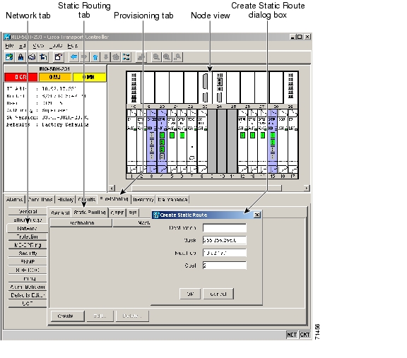
13.3.1 Creating a Static Route
Use this procedure to create a static route. Static routes are used for two purposes:
Step 1
Step 2
Figure 13-1 Create Static Route Dialog Box
Step 3
•
•
•
•
Step 4
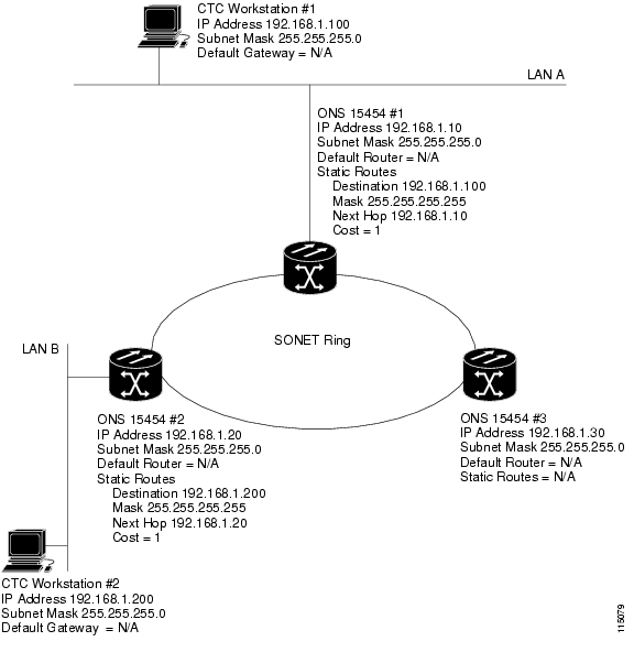
13.3.2 Static Route for Multiple CTCs
Figure 13-2 shows a static route used when multiple CTC computers need to access ONS 15454 nodes residing on the same subnet. In this scenario, CTC Workstations #1 and #2 and all ONS 15454 nodes are on the same IP subnet; ONS 15454 #1 and CTC Workstation #1 are attached to LAN A. ONS 15454 #2 and CTC Workstation #2 are attached to LAN B. Static routes are added to ONS 15454 #1 pointing to CTC Workstation #1, and to ONS 15454 #2 pointing to CTC Workstation #2. The static route is entered from the node's perspective.
Figure 13-2 Static Route for Multiple CTCs
13.4 OSPF
Open Shortest Path First (OSPF) is a link state Internet routing protocol. Link state protocols use a "hello protocol" to monitor their links with adjacent routers and to test the status of their links to their neighbors. Link state protocols advertise their directly connected networks and their active links. Each link state router captures the link state "advertisements" and puts them together to create a topology of the entire network or area. From this database, the router calculates a routing table by constructing a shortest path tree. Routes are continuously recalculated to capture ongoing topology changes.
13.4.1 Using OSPF
ONS 15454 nodes use the OSPF protocol in internal ONS 15454 networks for node discovery, circuit routing, and node management. You can enable OSPF on the ONS 15454 nodes so that the ONS 15454 topology is sent to OSPF routers on a LAN. Advertising the ONS 15454 network topology to LAN routers eliminates the need to manually enter static routes for ONS 15454 subnetworks. Figure 13-3 shows a network enabled for OSPF. Figure 13-4 shows the same network without OSPF. Static routes must be manually added to the router in order for CTC computers on LAN A to communicate with ONS 15454 #2 and #3 because these nodes reside on different subnets.
OSPF divides networks into smaller regions, called areas. An area is a collection of networked end systems, routers, and transmission facilities organized by traffic patterns. Each OSPF area has a unique ID number, known as the area ID, that can range from 0 to 4,294,967,295. Every OSPF network has one backbone area called area 0. All other OSPF areas must connect to area 0.
When you enable ONS 15454 OSPF topology for advertising to an OSPF network, you must assign an OSPF area ID to the ONS 15454 network. Coordinate the area ID number assignment with your LAN administrator. In general, all DCC-connected ONS 15454 nodes are assigned the same OSPF area ID.
Figure 13-3 OSPF Enabled
Figure 13-4 OSPF Not Enabled
13.4.2 Setting Up OSPF
Use the following procedure to enable OSPF on each ONS 15454 node that you want included in the OSPF network topology.
ONS 15454 OSPF settings must match the router OSPF settings, so you must get the OSPF area ID, Hello and Dead intervals, and authentication key (if OSPF authentication is enabled) from the router to which the ONS 15454 network is connected before enabling OSPF.
Step 1
Step 2
Figure 13-5 Enabling OSPF on the ONS 15454 SONET
Step 3
•
•
Step 4
•
•
Step 5
•
•
•
Step 6
Note
•
•
•
•
•
•
Figure 13-6 OSPF Area Range Table and Virtual Link Table
Step 7
Note
a.
b.
–
–
–
–
–
c.
Step 8
a.
b.
–
–
–
–
–
–
c.
Step 9
If you changed the area ID, the TCC cards will reset, one at a time.
13.5 Using Routing Information Protocol
The Routing Information Protocol (RIP) is widely used for routing traffic in the global Internet. RIP is an interior gateway protocol, which means that it performs routing within a single autonomous system. Exterior gateway protocols, such as the Border Gateway Protocol (BGP), perform routing between different autonomous systems.
RIP sends routing-update messages at regular intervals and when the network topology changes. When a router receives a routing update that includes changes to an entry, it updates its routing table to reflect the new route. The metric value for the path is increased by one, and the sender is indicated as the next hop. RIP routers maintain only the best route (the route with the lowest metric value) to a destination. After updating its routing table, the router immediately begins transmitting routing updates to inform other network routers of the change. These updates are sent independently of the regularly scheduled updates that RIP routers send. Use the following procedure to configure the ONS 15454 for RIP:
Step 1
Note
Step 2
Step 3
Step 4
Step 5
Step 6
Step 7
13.6 Using the Proxy Server Features
The ONS 15454 proxy server is a set of functions that allows you to network ONS 15454 nodes in environments where visibility and accessibility between ONS 15454s and CTC computers must be restricted. For example, you can set up a network so that field technicians and network operation center (NOC) personnel can both access the same ONS 15454 nodes while preventing the field technicians from accessing the NOC LAN. To do this, one ONS 15454 is provisioned as a gateway NE (GNE) and the other ONS 15454 nodes are provisioned as element NEs (ENEs). The GNE ONS 15454 tunnels connections between CTC computers and ENE ONS 15454 nodes, providing management capability while preventing access for non-ONS 15454 management purposes.
The ONS 15454 proxy server performs the following tasks:
•
•
•
•
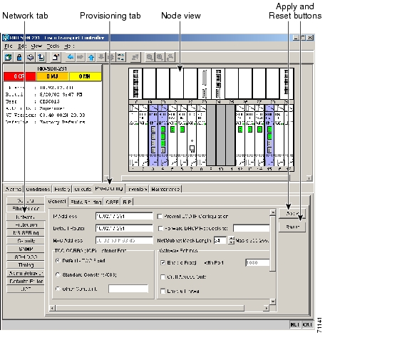
The ONS 15454 proxy server is provisioned using the following three check boxes in the Provisioning > Network > General tab (see Figure 13-7):
•
•
•
Figure 13-7 Proxy Server Gateway Settings
Figure 13-8 shows an ONS 15454 proxy server implementation. A GNE ONS 15454 is connected to a central office LAN and to ENE ONS 15454 nodes. The central office LAN is connected to a NOC LAN, which has CTC computers. The NOC CTC computer and craft technicians must both be able to access the ONS 15454 ENEs. However, the craft technicians must be prevented from accessing or seeing the NOC or central office LANs.
In the example, the ONS 15454 GNE is assigned an IP address within the central office LAN and is physically connected to the LAN through its LAN port. ONS 15454 ENEs are assigned IP addresses that are outside the central office LAN and given private network IP addresses. If the ONS 15454 ENEs are colocated, the craft LAN ports could be connected to a hub. However, the hub should have no other network connections.
Figure 13-8 ONS 15454 Proxy Server with GNE and ENEs on the Same Subnet
Table 13-2 shows recommended settings for ONS 15454 GNEs and ENEs in the configuration shown in Figure 13-8.
Figure 13-9 shows the implementation with ONS 15454 ENEs in multiple rings. In each example, ONS 15454 GNEs and ENEs are provisioned with the settings shown in Table 13-2.
Figure 13-9 ONS 15454 Proxy Server with ENEs on Multiple Rings
Table 13-3 shows the rules the ONS 15454 follows to filter packets when Enable Firewall is enabled. If the packet is addressed to the ONS 15454 SONET, additional rules, shown in Table 13-4, are applied. Rejected packets are silently discarded.
If you implement the proxy server, keep the following rules in mind:
1.
2.
3.
4.
5.
If nodes become unreachable in cases 1 and 2, you can correct the setting by performing one of the following:
•
•
13.7 Viewing the ONS 15454 Routing Table
ONS 15454 routing information is displayed on the Maintenance > Routing Table tabs ( Figure 13-10). The routing table provides the following information:
•
•
•
•
•
–
–
–
Figure 13-10 Viewing the ONS 15454 Routing Table
Table 13-5 shows sample routing entries for an ONS 15454 SONET.
Entry 1 shows the following:
•
•
•
•
Entry 2 shows the following:
•
•
•
•
Entry 3 shows the following:
•
•
•
•
Entry 4 shows the following:
•
•
•
•
Entry 5 shows a DCC-connected node that is accessible through a node that is not directly connected:
•
•
•
•
![]()
![]()
![]()
![]()
![]()
![]()
![]()
![]()
Posted: Sat Sep 16 09:50:39 PDT 2006
All contents are Copyright © 1992--2006 Cisco Systems, Inc. All rights reserved.
Important Notices and Privacy Statement.