|
|

Table Of Contents
SNMP MIB Installation and Configuration
5.1.2 ONS 15216 EDFA2 SNMP Elements
5.1.3 SNMP MIBs and Message Types
5.1.4 Command Syntax Using the SNMP Agent
5.2 Enabling SNMP Remote Management Community Strings
5.2.2 Creating a Community Entry
5.4.3 OverallStatusGroup Table
5.6.8 Database Backup and Restore
SNMP MIB Installation and Configuration
This chapter explains how to read and understand SNMP MIB as it relates to the Cisco ONS 15216 EDFA2. This chapter is a reference of all ONS 15216 EDFA2 SNMP commands that are used in a network management system (NMS). For provisioning the ONS 15216 EDFA2, see Chapter 4, "Provisioning Using ASH and SNMP".
5.1 SNMP Overview
Simple Network Management Protocol (SNMP) is an application-layer communication protocol that allows network devices to retrieve and modify the value of management information, as well as provide event notification to a NMS.
The ONS 15216 EDFA2 SNMP implementation uses proprietary and standard Internet Engineering Task Force (IETF) MIBs to convey inventory, fault, and performance management information.
SNMP allows limited management of the ONS 15216 EDFA2 by a generic, third-party SNMP manager (for example, HP OpenView Network Node manager [NNM] or Open Systems Interconnection [OSI] NetExpert).
The ONS 15216 EDFA2 supports SNMP Version 1 (SNMPv1) and SNMP Version 2c (SNMPv2c) protocols.
5.1.1 SNMP Components
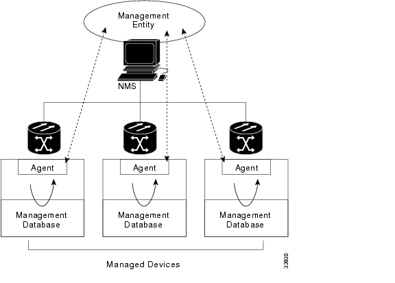
An SNMP-managed network consists of three primary components:
•
Managed devices
•
•
A managed device is a network node that contains an SNMP agent and resides on an SNMP-managed network. Managed devices collect and store management information and use SNMP to make this information available to management systems that use SNMP. Managed devices include routers, access servers, switches, bridges, hubs, computer hosts, and network elements such as the ONS 15216 EDFA2.
5.1.2 ONS 15216 EDFA2 SNMP Elements
The following three SNMP elements are used with the ONS 15216 EDFA2:
•
•
•
The SNMP elements are shown in Figure 5-1.
Figure 5-1 SNMP Elements
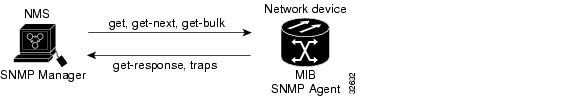
5.1.2.1 SNMP Agent
An agent is an entity that assumes an operation role to receive, process, and respond to requests, as well as generated event reports. The SNMP agent gathers data from the MIB, which is the repository for device parameter and network data. To respond to requests, the agent must have network management information access. To generate reports, an agent must be notified of internal events.
Cisco provides both an SNMP agent (installed on the ONS 15216 EDFA2) and SNMP MIB to monitor the ONS 15216 EDFA2. The SNMP agent software and MIB are pre-installed on each module.
Figure 5-2 shows the relationship between the SNMP agent and the MIB.
Figure 5-2 SNMP Agent and MIB
5.1.2.2 SNMP MIB
The SNMP MIBs (CERENT-15216-EDFA-MIB.mib and CERENT-GLOBAL-REGISTRY.mib) are files written in ASN.1 syntax. The CERENT-15216-EDFA-MIB.mib specifies what ONS 15216 EDFA2 information needs to be controlled and monitored. This MIB is pre-installed on the SNMP agent and is accessible via the CLI.
The CERENT-15216-EDFA-MIB.mib and other MIBs can also be installed on a third-party SNMP manager located at a network management center. The SNMP manager at the network management center or the SNMP manager, accessible via the CLI, (see SNMP Manager) uses the SNMP MIBs to communicate with the SNMP agent.
5.1.2.3 SNMP Manager
The ONS 15216 EDFA2 comes with a pre-installed SNMP manager accessible via the CLI. This SNMP manager can be accessed and used to communicate with the SNMP agent that is also pre-installed on each ONS 15216 EDFA2. This manual displays examples of issuing SNMP commands to the amplifier using the built-in SNMP manager.
5.1.2.3.1 Third-party, Vendor-Specific SNMP Managers
SNMP managers from third-party vendors running on a separate computer located at a network management center are often used to manage network elements. If a third-party SNMP manager is used, it must be able to communicate with the SNMP agent pre-installed on the ONS 15216 EDFA2.
If a third-party SNMP manager is used, it is assumed that the SNMP manager is pre-installed prior to the SNMP MIB installation. Each vendor-specific SNMP manager has an unique set of instructions for SNMP MIB installation. For directions on loading the SNMP MIBs, refer to SNMP manager documentation.
Cisco does not provide or recommend a standard third-party SNMP manager.
5.1.3 SNMP MIBs and Message Types
SNMP operations can be quite powerful. A manager can retrieve or modify the value of management information accessible by an agent, an agent can report an event to a manager, and the manager can inform another manager of the value of management information on an agent. Using retrieval and modification operations, a manager can cause an agent to perform an action or execute a command. The manager can also create new and delete existing instances of management information.
A MIB is a hierarchically-organized collection of information. Network management protocols, such as SNMP, gain access to these MIBs. MIBs consist of managed objects and are identified by object identifiers (OID).
The ONS 15216 EDFA2 SNMP agent communicates with an SNMP management application (a third-party application or the built-in SNMP manager) using SNMP messages. Table 5-1 describes SNMP operation types.
5.1.4 Command Syntax Using the SNMP Agent
Although Cisco has its own separate SNMP manager (Cisco Transport Manager [CTM]), management of the ONS 15216 EDFA2 is also possible using the built-in SNMP manager via the command line in the ASH shell, as described in SNMP Commands, page 6-15. The example commands and command syntax described in this manual are based on using the built-in ONS 15216 EDFA2 SNMP manager through the ASH shell CLI.
Commands can be issued via Telnet over a LAN or directly through the RS-232 (EIA/TIA-232) port on the module. (See .) After setting up a connection to the module and entering a password and user name, the following prompt appears:
ash:hostname:ONS15216 EDFA2>To communicate with the module using SNMP, the command must begin with "snmp".
Note
Example 5-1 snmp Command Followed by the Tab Key
ash:hostname:ONS15216 EDFA2> snmpagentattributehostmibpdurowsessionsubtreetabletraptreeContinue to enter operations from the list until the complete command is created. (See Example 5-2.)
Example 5-2 snmp table display Command
ash:hostname:ONS15216 EDFA2> snmp table display local cerentcerent15216EdfaCommunityEntrycerent15216EdfaCommTrapEntrycerent15216EdfaViewEntrycerent15216EdfaAgentControlGroupcerent15216EdfaActionOpGroupcerent15216EdfaLogEventControlcerent15216EdfaLogEventEntrycerent15216EdfaBootEntrycerent15216EdfaBootImageEntrycerent15216EdfaRtcDateAndTimecerent15216EdfaSromIpMgmtGroupcerent15216EdfaSromRingGroupcerent15216EdfaCfgGroupcerent15216EdfaOverallControlcerent15216EdfaPumpCfgEntrycerent15216EdfaOverallStatusGroupcerent15216EdfaPumpStatusEntrycerent15216EdfaAlarmEntrycerent15216EdfaVersionGroupcerent15216EdfaOpGroupash:hostname:ONS15216 EDFA2> snmp table display local cerent15216EdfaUse these commands to set up community strings ( Enabling SNMP Remote Management Community Strings) and traps ( Setting Up Traps).
5.2 Enabling SNMP Remote Management Community Strings
SNMP communities are groupings of workstations and servers (or gateways) that can manage the ONS 15216 EDFA2. NMSs use SNMP communities to enforce security. SNMP enforces security through password-like community strings. Access to the SNMP agent and the ONS 15216 EDFA2 can be limited by both IP address and community string.
The CLI SNMP manager (local SNMP manager) must be used to setup remote management (via a Telnet connection or terminal server). A third-party, vendor-specific SNMP manager cannot be used to setup remote management.
The process for setting up community entries consists of:
The ONS 15216 EDFA2 has the two default community strings listed in Table 5-2.
Table 5-2 Default Community Strings
public
read operations for all MIBs
private
read and write operations for all MIBs
The privileges assigned to the default strings can be modified or new communities with custom privileges can be created.
5.2.1 Creating a View
The following command describes how to set a view entry. A view defines and restricts the MIB attributes that a particular community can access. The view entry and the community entry are set to factory defaults. Users should consult with the Cisco TAC before modifying these settings.
5.2.1.1 Set View Entry
Command
snmp row set local cerent15216EdfaViewEntry
Syntax Description
snmp row set local cerent15216EdfaViewEntry view_index_# subtree
To create a community entry, a view must first be created. A MIB view can restrict the MIBs that a particular community can access. To create a view, type the command. view_index_# is an integer (1 to 2048) assigned to this view entry and subtree is the MIB subtree to which this view applies. Multiple view entries can be used for each view index.
This command creates a new row in the ViewEntry table. The SNMP manager prompts the user for each attribute.
To display a list of possible values, press the Spacebar followed by the Tab key. (See Example 5-3.)
Example 5-3 cerent15216EdfaViewEntry Set Command
ash:hostname:ONS15216 EDFA2> snmp row set local cerent15216EdfaViewEntry 1 cerentcerent15216EdfaViewMask '0'Hcerent15216EdfaViewType includedcerent15216EdfaViewStatusactivenotInServicenotReadycreateAndGocreateAndWaitdestroycerent15216EdfaViewStatus createAndGoash:hostname:ONS15216 EDFA2> snmp row display local cerent15216EdfaViewEntry 1 sampleCLASS cerent15216Edfa-AGENT-MIB.cerent15216EdfaViewEntry ::={cerent15216EdfaViewIndex = 1;cerent15216EdfaViewSubtree = { sample };cerent15216EdfaViewMask = '00'H;cerent15216EdfaViewType = included;cerent15216EdfaViewStatus = active;Access to the ONS 15216 EDFA2 can be restricted by IP address or community string using this command.
Table 5-3 describes the command and MIB view prompts.
5.2.2 Creating a Community Entry
SNMP communities are groupings of workstations and servers (or gateways) that can manage the ONS 15216 EDFA2. NMSs use SNMP communities to enforce security. Because access to the SNMP agent is controlled by a community entry, every SNMP agent must be configured to recognize one or more community names, and to provide the appropriate level of access to managers according to the community name. The following commands describe the commands for displaying or setting community entries. Users should consult with the Cisco TAC before modifying these settings.
5.2.2.1 Set CommunityEntry
Command
snmp row set local cerent15216EdfaCommunityEntry
Syntax Description
snmp row set local cerent15216EdfaCommunityEntry community_index_#
After creating a view, use the snmp row set local cerent15216EdfaCommunityEntry command to create a community entry for that view.
The SNMP manager prompts the user for each attribute. Press the Spacebar and then the Tab key after a prompt to view possible data inputs ( Example 5-4). Refer to Table 5-4 for information concerning data for each prompt.
Example 5-4 cerent15216EdfaCommunityEntry Set Command
ash:hostname:ONS15216 EDFA2> snmp row set local cerent15216EdfaCommunityEntry 3cerent15216EdfaCommName ""cerent15216EdfaCommViewIndex 0cerent15216EdfaCommPrivileges 35cerent15216EdfaCommSrcIPAddr 0.0.0.0cerent15216EdfaCommNetMask 0.0.0.0cerent15216EdfaCommStatus 0cerent15216EdfaCommStatus OBJECT-TYPESYNTAX INTEGER{active(1),notInService(2),notReady(3),createAndGo(4),createAndWait(5),destroy(6)}MAX-ACCESS read-createDESCRIPTION::= { cerent15216EdfaCommunityEntry 7 }Table 5-4 displays the definitions for the community entry values.
Table 5-4 Creating a Community Entry
cerent15216EdfaCommIndex
Community Index: An index that uniquely identifies a particular SNMP community. This community index is part of the command. In Example 5-4, it is "3".
cerent15216EdfaCommName
Community Name: The community string.
cerent15216EdfaCommViewIndex
View Index: The view index specifies which MIBs this particular community string can access.
cerent15216EdfaCommPrivileges
Privileges: A bitmap of access privileges that govern what management operations a particular community can perform. These privileges are expressed as a sum of values, where each value represents a particular operation. Refer to Table 5-5 for the SNMP Operation Decimal Values.
cerent15216EdfaCommSrcIPAddr
Source IP Address: The IP address from which network management traffic for this community originates.
cerent15216EdfaCommNetMask
NetMask: The subnet mask for the source IP address.
cerent15216EdfaCommStatus
Status: The status of this conceptual row in the community table.Use createAndGo to create a new row. Use active to modify an existing row.
5.2.2.2 Display CommunityEntry
Command
snmp row display local cerent15216EdfaCommunityEntry
Syntax Description
snmp row display local cerent15216EdfaCommunityEntry community_index_#
After creating a community string, use this command to view its parameters. The number in the command refers to the community index number created in the previous section.
Example 5-5 cerent15216EdfaCommunityEntry Display Command
ash:hostname:ONS15216 EDFA2> snmp row display local cerent15216EdfaCommunityEntry 1CLASS cerent15216Edfa-AGENT-MIB.cerent15216EdfaCommunityEntry ::={cerent15216EdfaCommIndex = 1;cerent15216EdfaCommName = "private";cerent15216EdfaCommViewIndex = 1;cerent15216EdfaCommPrivileges = 255;cerent15216EdfaCommSrcIPAddr = 0.0.0.0;cerent15216EdfaCommNetMask = 255.255.255.255;cerent15216EdfaCommStatus = active;};Table 5-5 displays the decimal values for the following SNMP operations.
For example, 255 is the sum of all decimal values and specifies access to all SNMP operations. This sum is the default private community. 247 is the sum for all SNMP operations with the exception of the Set operation. This sum is the default public community.
5.3 Setup for CTM Access
Use the following procedure to configure a new ONS 15216 EDFA2 for Cisco Transport Manager (CTM) access:
Step 1
Amp01:ONS15216 EDFA2> ACT-USER::CISCO15:123::;Step 2
Amp01:ONS15216 EDFA2> ED-PID::CISCO15:124::,admin15##;Step 3
Amp01:ONS15216 EDFA2> ED-NE-GEN:::125:::NAME= , IPADDR= , IPMASK= , DEFRTR= ;Step 4
Amp01:ONS15216 EDFA2> ED-DAT:::126::2003-06-18,08-49-00;Step 5
Amp01:ONS15216 EDFA2> INIT-SYS::ALL:127::1;Step 6
telnet <ONS 15216 EDFA2 IP address> 8023Step 7
Step 8
ash:hostname:ONS15216 EDFA2> snmp row set local cerent15216EdfaCommunityEntry 2 (Do not
use Entry 1 which is the RO public community)
cerent15216EdfaCommIndex = 2 (if the CommunityEntry is 2)cerent15216EdfaCommName = "private" (must match the CTM community string entry)cerent15216EdfaCommViewIndex = 1cerent15216EdfaCommPrivileges = 255cerent15216EdfaCommSrcIPAddr = 0.0.0.0 (for more security, enter CTM A's IP address)cerent15216EdfaCommNetMask = 255.255.255.255cerent15216EdfaCommStatus = 4 (active(1),notInService(2),notReady(3),createAndGo(4),createAndWait(5),destroy(6))ash:hostname:ONS15216 EDFA2> snmp row set local cerent15216EdfaCommunityEntry 3cerent15216EdfaCommIndex = 3 (if the CommunityEntry is 3)cerent15216EdfaCommName = "private" (must match the CTM community string entry)cerent15216EdfaCommViewIndex = 1cerent15216EdfaCommPrivileges = 255cerent15216EdfaCommSrcIPAddr = 0.0.0.0 (for more security, enter CTM B's IP address)cerent15216EdfaCommNetMask = 255.255.255.255cerent15216EdfaCommStatus = 4 (active(1),notInService(2),notReady(3),createAndGo(4),createAndWait(5),destroy(6))Step 9
ash:hostname:ONS15216 EDFA2> snmp table display local cerent15216EdfaCommunityEntryStep 10
ash:hostname:ONS15216 EDFA2> snmp row set local cerent15216EdfaCommTrapEntry 1cerent15216EdfaCommTrapCommunity "private"cerent15216EdfaCommTrapDestIPAddress <CTM A's IP address>cerent15216EdfaCommTrapDestUDPPort 162cerent15216EdfaCommTrapViewIndex 1cerent15216EdfaCommTrapVersion v2cerent15216EdfaCommTrapStatus 4ash:hostname:ONS15216 EDFA2> snmp row set local cerent15216EdfaCommTrapEntry 2cerent15216EdfaCommTrapCommunity "private"cerent15216EdfaCommTrapDestIPAddress <CTM B's IP address>cerent15216EdfaCommTrapDestUDPPort 162cerent15216EdfaCommTrapViewIndex 1cerent15216EdfaCommTrapVersion v2cerent15216EdfaCommTrapStatus 4Step 11
ash:hostname:ONS15216 EDFA2> snmp table display local cerent15216EdfaCommTrapEntryStep 12
ash:hostname:ONS15216 EDFA2> snmp attribute set local cerent15216EdfaAgentTrapEnable 1Step 13
ash:hostname:ONS15216 EDFA2> snmp attribute get local cerent15216EdfaAgentTrapEnableStep 14
ash:hostname:ONS15216 EDFA2> snmp attribute set local sysName <NE ID>Step 15
ash:hostname:ONS15216 EDFA2> snmp attribute set local cerent15216EdfaActionOpSaveConfig
perform
Step 16
ash:hostname:ONS15216 EDFA2> logoff5.4 Tables and Groups
The cerent15216Edfa.mib contains several key tables that are used to review and provision the ONS 15216 EDFA2. The following tables are listed and described in the following sections:
5.4.1 CfgGroup Table
The cerent15216EdfaCfgGroup table is used to set or get alarm threshold configuration. The associated table command provides a summary of all alarm thresholds. See Table 5-6 for variable definitions. For more information on alarm thresholds, see the "Set Alarm Thresholds" section on page 4-5.
Use the snmp attribute set local cerent15216EdfaOpSaveConfig perform command to save changes.
5.4.2 PumpCfgEntry Table
The cerent15216EdfaPumpCfgEntry table is used to set or get laser pump control mode configuration. The associated table command displays a settings summary or allows you to set pumps. See Table 5-7 for variable definitions. The factory default pump control mode for the ONS 15216 EDFA2 is Constant Gain Temperature Compensated. Cisco recommends that users contact the Cisco TAC prior to changing this mode of operation.
5.4.2.1 Changing the Pump Control Mode
For Constant Gain Temperature Compensated mode, the system automatically sets the second pump to this mode when either pump is set.
Constant Output Power mode is only valid for pump 2. If pump 2 is set to Constant Output Power Mode, pump 1 is automatically set to Constant Pump Power mode with a value of 75 mW.
For Constant Pump Current or Constant Pump Power mode, the user should set both pump modes to be the same.
Warning
To set the ONS 15216 EDFA2 to Constant Pump Current mode, use the following steps:
Step 1
a.
b.
Step 2
Step 3
a.
b.
Step 4
Example 5-6 shows how to set the ONS 15216 EDFA2 to Constant Pump Current mode and then set it back to Constant Gain Temperature Compensated mode. (Setting pump 1 or 2 to Constant Gain Temperature Compensated mode sets both pumps to that mode.)
Example 5-6 Setting Mode to Constant Pump Current and then Back to Constant Gain Temperature Compensated
ash:hostname:ONS15216 EDFA2> snmp attribute set local cerent15216EdfaPumpCfgConstPumpCurrent 1 200ash:hostname:ONS15216 EDFA2> snmp attribute set local cerent15216EdfaPumpCfgConstPumpCurrent 2 200ash:hostname:ONS15216 EDFA2> snmp attribute set local cerent15216EdfaPumpCfgControlMode 1constGainTempCompconstOutputPowerconstCurrentconstPoweridleash:hostname:ONS15216 EDFA2> snmp attribute set local cerent15216EdfaPumpCfgControlMode 1 constCurrentash:hostname:ONS15216 EDFA2> snmp attribute set local cerent15216EdfaPumpCfgControlMode 2 constCurrentash:hostname:ONS15216 EDFA2> snmp attribute set local cerent15216EdfaPumpCfgControlMode 1 constGainTempComp5.4.2.2 Changing the Pump Control Value
To change the control value for Constant Gain Temperature Compensated mode, the user must set a new value of cerent15216EdfaConstGainOverallGain.
Constant Output Power Mode is only valid for pump 2. To change the control value for pump 2, the user must set the new value of cerent15216EdfaPumpCfgConstOutPower for pump 2 and then set the pump to Constant Output Power mode for the setting to take effect. Pump 1 is automatically set to Constant Pump Power mode with a value of 75 mW.
To change the control value for Constant Pump Current mode, the user must set new values of cerent15216EdfaPumpCfgConstPumpCurrent for both pumps and then set the pump control mode for both pumps for the setting to take effect.
To change the control value for Constant Pump Power mode, the user must set new values of cerent15216EdfaPumpCfgConstPumpPower for both pumps and then set the pump control mode for both pumps for the setting to take effect.
For example, to change the value for Constant Pump Current mode, use the following steps:
Step 1
a.
b.
Step 2
Step 3
a.
b.
Step 4
Example 5-7 shows how to set the value for Constant Pump Current mode to be 200 mA and then set the mode to Constant Pump Current mode again for the settings to take effect.
Example 5-7 Changing Value for Constant Pump Current Mode
ash:hostname:ONS15216 EDFA2> snmp attribute set local cerent15216EdfaPumpCfgConstPumpCurrent 1 200ash:hostname:ONS15216 EDFA2> snmp attribute set local cerent15216EdfaPumpCfgConstPumpCurrent 2 200ash:hostname:ONS15216 EDFA2> snmp attribute set local cerent15216EdfaPumpCfgControlMode 1 constCurrentash:hostname:ONS15216 EDFA2> snmp attribute set local cerent15216EdfaPumpCfgControlMode 2 constCurrent5.4.3 OverallStatusGroup Table
The cerent15216EdfaOverallStatusGroup table allows users to display the input and output of the ONS 15216 EDFA2 amplifier. Table 5-8 describes cerent15216EdfaOverallStatusGroup table variables.
Note
5.4.4 OverallControl Table
The cerent15216EdfaOverallControl table allows the user to display and configure overall gain and pre-attenuation. Table 5-9 describes cerent15216EdfaOverallControl variables.
5.4.5 PumpStatusEntry Table
The cerent15216EdfaPumpStatusEntry table is used to display optical amplification module data. Table 5-10 displays information regarding the cerent15216EdfaPumpStatusEntry table variables.
Table 5-10 cerent15216EdfaPumpStatusEntry Variable Descriptions
cerent15216EdfaPumpStatusPumpNum
cerent15216EdfaPumpNumber
Read-only
Laser pump number
cerent15216EdfaPumpStatusLaserChipTemp
Integer (-9999 to 9999)
Read-only
Laser chip temperature (*10ΑC)
cerent15216EdfaPumpStatusLaserChipTempSetpoint
Integer (0 to 999)
Read-only
Laser chip temperature setpoint (*10ΑC)
cerent15216EdfaPumpStatusLaserTECCurrent
Integer (0 to 99999)
Read-only
Laser TEC current (mA)
cerent15216EdfaPumpStatusLaserPower
Integer (0 to 99999)
Read-only
Laser power (*100 mW)
cerent15216EdfaPumpStatusLaserCurrent
Integer (0 to 999999)
Read-only
Laser current (*100 mA)
cerent15216EdfaPumpStatusAmbientTemp
Integer (-9999 to 9999)
Read-only
Ambient temperature (*100ΑC)
cerent15216EdfaPumpStatusDCVoltage
Integer (0 to 9999)
Read-only
DC voltage (*10V)
cerent15216EdfaPumpStatusInPoweruW
Integer (0 to 99999)
Read-only
Input power (*10 microW)
cerent15216EdfaPumpStatusInPowerdBm
Integer
(-999999 to 999999)
Read-only
Input power (*100 dBm)
cerent15216EdfaPumpStatusOutPowermW
Integer (0 to 999999)
Read-only
Output power (*100 mW)
cerent15216EdfaPumpStatusOutPowerdBm
Integer
(-99999 to 99999)
Read-only
Output power (*100 dBm)
cerent15216EdfaPumpStatusGain1
Integer (-9999 to 9999)
Read-only
Gain (*10 dB)
1 The value of the cerent15216EdfaPumpStatusGain variable should always be around 23 dB. This variable is the internal amplifier module gain. The cerent15216EdfaPumpStatusGain variable should not be confused with the cerent15216EdfaConstGainOverallGain variable that is used to set the gain of the ONS 15216 EDFA2. The cerent15216EdfaPumpStatusGain is the value of the gain of the amplification module only, it does not take into account the VOA (variable optical attenuator) attenuation. If you try to calculate the gain using the values of the PumpStatusOutPowerdBm - PumpStatusInPowerdBm you will not get the exact PumpStatusGain value. A more complex calculation is required to get the gain value. It needs to take ASE (amplified spontaneous emission) into account. This is often called the amplifier noise. This variable will be more dominant when the input power to the amplifier is low.
5.4.6 AlarmEntry Table
The cerent15216EdfaAlarmEntry table is used to display alarm status. The associated table command provides a summary of all alarms. Table 5-11describes the cerent15216EdfaAlarmEntry table variables.
5.4.7 OpGroup Table
The cerent15216EdfaOpGroup table is used to display or set operation actions, such as saving configuration or loading new software. The individual variables in Table 5-12 are generally used instead of the table command. That is, when performing a cutover command, the user would use the snmp attribute set local cerent15216EdfaOpCutover perform command.
5.4.8 VersionGroup Table
The cerent15216EdfaVersionGroup table allows users to display the currently loaded image and the image to be loaded after cutover. Table 5-13 describes cerent15216EdfaVersionGroup table variables.
5.5 Setting Up Traps
Traps are asynchronous notifications sent from the ONS 15216 EDFA2 to a predetermined location (IP address, subnet mask, etc.). A community entry must be created prior to remotely setting up traps using either Telnet or a terminal server. Table 5-14 displays the alarm notification types in the cerent15216Edfa.mib that initiate a trap.
5.5.1 Display Trap Command
Command
snmp table display local cerent15216EdfaCommTrapEntry
Syntax Description
snmp table display local cerent15216EdfaCommTrapEntry #
Displays the communities for traps. See Example 5-8
Example 5-8 cerent15216EdfaCommTrapEntry Display Command
ash:hostname:ONS15216 EDFA2> snmp table display local cerent15216EdfaCommTrapEntryCLASS CERENT-15216-EDFA-MIB.cerent15216EdfaCommTrapEntry ::={cerent15216EdfaCommTrapIndex = 1;cerent15216EdfaCommTrapCommunity = "private";cerent15216EdfaCommTrapDestIPAddress = 172.22.87.50;cerent15216EdfaCommTrapDestUDPPort = 162;cerent15216EdfaCommTrapViewIndex = 1;cerent15216EdfaCommTrapVersion = v2;cerent15216EdfaCommTrapStatus = active;};5.5.2 Set Trap Command
Command
snmp row set local cerent15216EdfaCommTrapEntry
Syntax Description
snmp row set local cerent15216EdfaCommTrapEntry #
The command followed by a community number permits the user to set the parameters for the SNMP trap. Example 5-9 displays the prompts that appear after entering the command.
Prompts appear for the following settings:
•
•
•
•
•
•
If the data needs to be changed, enter new data after the prompt.
Example 5-9 cerent15216EdfaCommTrapEntry Set Command
ash:hostname:ONS15216 EDFA2> snmp row set local cerent15216EdfaCommTrapEntry 1cerent15216EdfaCommTrapCommunity "private"cerent15216EdfaCommTrapDestIPAddress 172.22.87.50cerent15216EdfaCommTrapDestUDPPort 162cerent15216EdfaCommTrapViewIndex 1cerent15216EdfaCommTrapVersion v2cerent15216EdfaCommTrapStatus 4ash:hostname:ONS15216 EDFA2>5.5.3 Set Agent Trap Enable
Command
snmp attribute set local cerent15216EdfaAgentTrapEnable
Syntax Description
snmp attribute set local cerent15216EdfaAgentTrapEnable control
Enables or disables SNMP traps depending on whether the parameter control is "enabled" or "disabled".
5.5.4 Get Agent Trap Enable
Command
snmp attribute get local cerent15216EdfaAgentTrapEnable
Syntax Description
snmp attribute get local cerent15216EdfaAgentTrapEnable
Gets the SNMP enable trap status. The system responds with either "enabled" or "disabled".
5.6 Retrieving Information
The following SNMP commands access ONS 15216 EDFA2 information.
5.6.1 IP Address
Command
snmp table display local cerent15216EdfaSromIpMgmtGroup
Syntax Description
snmp table display local cerent15216EdfaSromIpMgmtGroup
Displays the ONS 15216 EDFA2 IP address.
The following SNMP command displays the ONS 15216 EDFA2's IP address and other networking information:
•
Example 5-10 cerent15216EdfaSromIpMgmtGroup Display Command
ash:hostname:ONS15216 EDFA2> snmp row display local cerent15216EdfaSromIpMgmtGroupCLASS cerent15216Edfa-SROM-IP-ADDRESS-MIB.cerent15216EdfaSromIpMgmtGroup ::={cerent15216EdfaSromIpMgmtEnetAddress = 172.22.82.19;cerent15216EdfaSromIpMgmtEnetSubNetMask = 255.255.0.0;cerent15216EdfaSromIpMgmtDefaultRouterAddress = 172.22.82.1;cerent15216EdfaSromIpMgmtHostName = "hostname";};Table 5-15 describes the other attributes displayed by these commands.
5.6.2 Date and Time
Command
snmp attribute get local cerent15216EdfaRtcDateAndTime
Syntax Description
snmp attribute get local cerent15216EdfaRtcDateAndTime
Displays the date and time for the ONS 15216 EDFA2.
The following SNMP command displays the date and time for the ONS 15216 EDFA2 and other time data:
•
The following SNMP command sets the date and time for the ONS 15216 EDFA2 and other time data:
•
When setting the local time of day, set the time zone first, set the DST offset second, and set the local time last. Entries must follow this format: "yyyy-m-d,h:m:s.s +h:m". Following the space, the time zone is set as +/- hours from Greenwich Mean Time (GMT) (also designated as universal coordinated time (UTC)) followed by a colon and minutes ahead for daylight savings. For example, Pacific Daylight Time would be -8:60 and Greenwich Mean Time would be +0:0.
Example 5-11 displays the ONS 15216 EDFA2 command for displaying the date and time.
Example 5-11 cerent15216EdfaRtcDateAndTime Display Command
ash:hostname:ONS15216 EDFA2> snmp row display local cerent15216EdfaRtcDateAndTimeCLASS CERENT-15216-EDFA-MIB.cerent15216EdfaRtcDateAndTime ::={cerent15216EdfaRtcDateAndTimeLocal = '07d20716070a2a042d083c'H;cerent15216EdfaRtcDateAndTimeGMT = '07d207160e0a2a042b0000'H;cerent15216EdfaRtcDateAndTimeLocalString = "2002-7-22,7:10:42.4 -8:60";cerent15216EdfaRtcDateAndTimeGMTString = "2002-7-22,14:10:42.4 +0:0";cerent15216EdfaRtcDateAndTimeTimezone = -8;cerent15216EdfaRtcDateAndTimeSaving = 60;cerent15216EdfaRtcDateAndTimeFormsString = "07/22/2002 07:10:42";};Table 5-16 describes the attributes displayed by these commands.
5.6.3 Power Gain
Command
snmp attribute get local cerentEdfa15216EdfaConstGainOverallGain
Syntax Description
snmp attribute get local cerentEdfa15216EdfaConstGainOverallGain #
Displays the overall power gain when the ONS 15216 EDFA2 is in Constant Gain Temperature Compensated mode.
The following commands access overall power gain when in the Constant Gain Temperature Compensated mode:
•
•
The cerent15216EdfaConstGainOverallGain attribute in cerent15216EdfaOverallControl display command shows the ONS 15216 EDFA2 power gain ( Example 5-12).
Example 5-12 cerent15216EdfaOverallControl Display Command
ash:hostname:ONS15216 EDFA2>snmp row display local cerent15216EdfaOverallControlCLASS CERENT-15216-EDFA-MIB.cerent15216EdfaOverallControl ::={cerent15216EdfaConstGainOverallGain = 220;cerent15216EdfaVariableGainPreAttenuation = 10;};For information about all of the parameters in the cerent15216EdfaOverallStatusGroup, refer to Table 5-8.
5.6.4 Case Temperature
5.6.4.1 Case Temperature Value
Command
snmp attribute get local cerent15216EdfaPumpStatusAmbientTemp
Syntax Description
snmp attribute get local cerent15216EdfaPumpStatusAmbientTemp pump#
Displays case temperature value (where pump# is the pump number).
The following command displays the temperature value (where pump# is the pump number) and other pump status data:
•
The cerent15216EdfaPumpStatusAmbientTemp attribute of the cerent15216EdfaPumpStatusEntry display command shows the case temperature ( Example 5-13).
Example 5-13 cerent15216EdfaPumpStatusEntry Display Command
ash:hostname:ONS15216 EDFA2> snmp row display local cerent15216EdfaPumpStatusEntry 1CLASS CERENT-15216-EDFA-MIB.cerent15216EdfaPumpStatusEntry ::={cerent15216EdfaPumpStatusPumpNum = 1;cerent15216EdfaPumpStatusLaserChipTemp = 260;cerent15216EdfaPumpStatusLaserChipTempSetpoint = 260;cerent15216EdfaPumpStatusLaserTECCurrent = 20;cerent15216EdfaPumpStatusLaserPower = 8503;cerent15216EdfaPumpStatusLaserCurrent = 17010;cerent15216EdfaPumpStatusAmbientTemp = 2272;cerent15216EdfaPumpStatusDCVoltage = 52;cerent15216EdfaPumpStatusInPoweruW = 250;cerent15216EdfaPumpStatusInPowerdBm = -600;cerent15216EdfaPumpStatusOutPowermW = 5000;cerent15216EdfaPumpStatusOutPowerdBm = 1700;cerent15216EdfaPumpStatusGain = 220;};Refer to Table 5-10 for information about all of the parameters in the cerent15216EdfaPumpStatusEntry table.
5.6.4.2 Case Temperature Alarm Threshold
5.6.4.2.1 CtmpMin
Command
snmp attribute get local cerent15216EdfaCtmpMin
Syntax Description
snmp attribute get local cerent15216EdfaCtmpMin
This command displays minimum case temperature alarm threshold.
5.6.4.2.2 CtmpMax
snmp attribute get local cerent15216EdfaCtmpMax
Syntax Description
snmp attribute get local cerent15216EdfaCtmpMax
This command displays maximum case temperature alarm threshold.
The following command displays case temperature alarm threshold and other temperature data:
•
This command is shown in Example 5-14.
Example 5-14 cerent15216EdfaCfgGroup Display Command
ash:hostname:ONS15216 EDFA2> snmp row display local cerent15216EdfaCfgGroupCLASS CERENT-15216-EDFA-MIB.cerent15216EdfaCfgGroup ::={cerent15216EdfaCfgSaved = true;cerent15216EdfaLpoutSetpoint = 0;cerent15216EdfaLpoutDeviation = 200;cerent15216EdfaLpoutHysteresis = 100;cerent15216EdfaLOSThreshold = -3102;cerent15216EdfaLOSHysteresis = 100;cerent15216EdfaCtmpMin = -5;cerent15216EdfaCtmpMinHysteresis = 1;cerent15216EdfaCtmpMax = 65;cerent15216EdfaCtmpMaxHysteresis = 1;cerent15216EdfaCLEI = "WMM4180BRA";cerent15216EdfaPowerBusMode = duplex;cerent15216EdfaPowerBusDCVoltageMin = 420;cerent15216EdfaPowerBusDCVoltageMax = 700;};Refer to Table 5-8 for information about all of the parameters in cerent15216EdfaOverallStatusGroup.
5.6.4.3 Case Temperature Alarm Hysteresis
5.6.4.3.1 CtmpMaxHysteresis
Command
snmp attribute get local cerent15216EdfaCtmpMaxHysteresis
Syntax Description
snmp attribute get local cerent15216EdfaCtmpMaxHysteresis
Displays maximum case temperature alarm hysteresis.
The cerent15216EdfaCtmpMaxHysteresis attribute in the cerent15216EdfaCfgGroup display command shows the maximum case hysteresis temperature alarm threshold ( Example 5-14). Refer to Table 5-6 for information about all of the parameters in cerent15216EdfaCfgGroup.
5.6.4.3.2 CtmpMinHysteresis
Command
snmp attribute get local cerent15216EdfaCtmpMinHysteresis
Syntax Description
snmp attribute get local cerent15216EdfaCtmpMinHysteresis
Displays the minimum case hysteresis temperature alarm threshold.
The following command displays case temperature alarm hysteresis and other data:
•
The cerent15216EdfaCfgGroup command is shown in Example 5-14. For information about all of the parameters in the cerent15216EdfaCfgGroup table, see Table 5-6.
5.6.5 Power Bus
5.6.5.1 Power Bus Mode
Command
snmp attribute get local cerent15216EdfaPowerBusMode
Syntax Description
snmp attribute get local cerent15216EdfaPowerBusMode
Displays the power bus mode (simplex or duplex).
The following command displays power bus voltage and other data:
•
5.6.5.2 Power Bus Alarm Threshold
5.6.5.2.1 PowerBusDCVoltageMax
Command
snmp attribute get local cerent15216EdfaPowerBusDCVoltageMax
Syntax Description
snmp attribute get local cerent15216EdfaPowerBusDCVoltageMax
Displays the maximum allowable power bus DC voltage (multiplied by -10V).
The following command displays power bus voltage and other data:
•
5.6.5.2.2 PowerBusDCVoltageMin
Command
snmp attribute get local cerent15216EdfaPowerBusDCVoltageMin
Syntax Description
snmp attribute get local cerent15216EdfaPowerBusDCVoltageMin
Displays the minimum allowable power bus DC voltage (multiplied by -10V).
The following command displays power bus voltage and other data:
•
5.6.6 Input Power (Signal)
5.6.6.1 Input Power (Signal) Value
5.6.6.1.1 InPowerduW
Command
snmp attribute get local cerent15216EdfaInPoweruW
Syntax Description
snmp attribute get local cerent15216EdfaInPoweruW
Displays input power value in microwatts.
The following command displays the ONS 15216 EDFA2 input power value and other status information:
•
For information about all of the parameters in the cerent15216EdfaOverallStatusGroup table, see Table 5-8.
5.6.6.1.2 InPowerdBm
Command
snmp attribute get local cerent15216EdfaInPowerdBm
Syntax Description
snmp attribute get local cerent15216EdfaInPowerdBm
Displays the input power value in dBm. The dBm units are converted from ΒW to dBm, so theses values could be slightly different due to rounding error.
The following command displays input power value and other status information:
•
For information about all of the parameters in the cerent15216EdfaOverallStatusGroup table, refer to Table 5-8.
5.6.6.2 Loss of Signal (Input Power) Alarm Threshold
Command
snmp attribute get local cerent15216EdfaLOSThreshold
Syntax Description
snmp attribute get local cerent15216EdfaLOSThreshold
Displays the loss of signal (input power) alarm threshold.
The following command displays the loss of input power alarm threshold and other laser power and temperature data:
•
The cerent15216EdfaLOSThreshold attribute in the cerent15216EdfaCfgGroup display command shows the loss of input power alarm threshold ( Example 5-14).
For information about all of the parameters in the cerent15216EdfaCfgGroup table, refer to Table 5-6.
5.6.6.3 Loss of Signal (Input Power) Alarm Hysteresis
Command
snmp attribute get local cerent15216EdfaLOSHysteresis
Syntax Description
snmp attribute get local cerent15216EdfaLOSHysteresis
Displays the loss of signal (input power) alarm hysteresis value.
The following command displays the loss of input power hysteresis value and other laser power and temperature data:
•
The cerent15216EdfaLOSHysterisis attribute in the cerent15216EdfaCfgGroup display command shows the loss of input power alarm threshold ( Example 5-14). For information about all of the parameters in the cerent15216EdfaCfgGroup table, refer to Table 5-6.
5.6.7 Output Power
5.6.7.1 Output Power Value
5.6.7.1.1 OutPowermW
Command
snmp attribute get local cerent15216EdfaOutPowermW
Syntax Description
snmp attribute get local cerent15216EdfaOutPowermW
Displays output power value in milliwatts.
The snmp row display local cerent15216EdfaOverallStatusGroup command displays the ONS 15216 EDFA2 output power value and additional pump status. For information about all of the parameters in the cerent15216EdfaOverallStatusGroup table, refer to Table 5-8.
5.6.7.1.2 OutPowerdBm
Command
snmp attribute get local cerent15216EdfaOutPowerdBm
Syntax Description
snmp attribute get local cerent15216EdfaOutPowerdBm
Displays output power value in dBm. This command displays loss of output power value and additional pump status data. The dBm units are converted from mW to dBm, so theses values could be slightly different due to rounding error.
For information about all of the parameters in the cerent15216EdfaOverallStatusGroup table, refer to Table 5-8.
5.6.7.2 Loss of Output Power Alarm Setpoint
5.6.7.2.1 LpoutSetpoint
Command
snmp attribute get local cerent15216EdfaLpoutSetpoint
Syntax Description
snmp attribute get local cerent15216EdfaLpoutSetpoint
This attribute notifies network operations personnel notification if the output power of the ONS 15216 EDFA2 drops below a level that impacts proper operation of the optical network.
Typically, network operations personnel should set the loss of output power alarm threshold at a value that is appropriate for the intended network application so that the alarm condition is meaningful. Consult with the Cisco TAC to determine threshold value for your application. As a guideline, Cisco recommends that loss of output power alarm threshold value be set at 1 dB below the current output power level of the amplifier.
When the ONS 15216 EDFA2 is set to Constant Gain Temperature Compensated mode (factory default), the value for loss of output power alarm threshold cannot be changed. To display the loss of output power alarm threshold and other power and temperature alarm data, use the snmp table display local cerent15216EdfaCfgGroup command (shown in Example 5-14). This command returns the current alarm threshold default values.
5.6.7.2.2 LpoutDeviation
Command
snmp attribute get local cerent15216EdfaLpoutDeviation
Syntax Description
snmp attribute get local cerent15216EdfaLpoutDeviation
This attribute is not required when operating in factory default Constant Gain Temperature Compensated mode. Setting of the loss of output power alarm deviation is only necessary when the amplifier is used in Constant Output Power mode.
This attribute is used to set the amount by which the output power must vary from the threshold set point before the alarm is activated. This attribute, in conjunction with the loss of output power alarm threshold and hysteresis, enables notification of network operations personnel if the output power of the ONS 15216 EDFA2 drops below a level that would impact proper operation of the optical network.
Typically, network operations personnel should set the loss of output power alarm deviation at a value that is appropriate for the intended network application so that the alarm condition is meaningful. Consult with the Cisco TAC to determine the deviation value for your application. As a guideline, Cisco recommends that the loss of output power alarm deviation value be set at 2 dB. The module triggers an alarm if it detects a signal level of 2 dB below the current output power alarm level threshold value set for the amplifier.
When the ONS 15216 EDFA2 is set to Constant Gain Temperature Compensated mode (factory default), the value for the loss of output power alarm threshold cannot be changed. To display the loss of output power alarm deviation and other power and temperature alarm data, use the snmp table display local cerent15216EdfaCfgGroup command as shown in Example 5-14. This command returns the current alarm threshold default values.
To set the loss of output power alarm deviation when the ONS 15216 EDFA2 is configured for operation in Constant Output Power or Constant Pump Power mode, type snmp attribute set local cerent15216EdfaLpoutDeviation at the command prompt followed by a number (as shown in Example 5-15). Valid entries are between 0 and 1000 and are in dB times 100. For example, if the loss of output power deviation required were 0.2 dB, the number input as the loss of output power alarm deviation would be 20.
The user is prompted to modify the attribute. If no changes are required, press Enter to return to command prompt.
Example 5-15 cerent15216EdfaLpoutDeviation Set Command
ash:hostname:ONS15216 EDFA2> snmp attribute set local cerent15216EdfaLpoutDeviation 200ash:hostname:ONS15216 EDFA2> snmp row display local cerent15216EdfaCfgGroupCLASS CERENT-15216-EDFA-MIB.cerent15216EdfaCfgGroup ::={cerent15216EdfaCfgSaved = false;cerent15216EdfaLpoutSetpoint = 0;cerent15216EdfaLpoutDeviation = 200;cerent15216EdfaLpoutHysteresis = 100;cerent15216EdfaLOSThreshold = -2694;cerent15216EdfaLOSHysteresis = 100;cerent15216EdfaCtmpMin = -5;cerent15216EdfaCtmpMinHysteresis = 1;cerent15216EdfaCtmpMax = 65;cerent15216EdfaCtmpMaxHysteresis = 1;cerent15216EdfaCLEI = "WMAW27VLAA";cerent15216EdfaPowerBusMode = duplex;cerent15216EdfaPowerBusDCVoltageMin = 420;cerent15216EdfaPowerBusDCVoltageMax = 700;};Changes must be saved before terminating the session. See the "Save Changes" section on page 4-11.
5.6.7.3 Loss of Output Power Alarm Hysteresis
Command
snmp attribute get local cerent15216EdfaLpoutHysteresis
Syntax Description
snmp attribute get local cerent15216EdfaLpoutHysteresis
This attribute is not required when operating in factory default Constant Gain Temperature Compensated mode. Setting of the loss of output power alarm deviation is only necessary when the amplifier is used in Constant Output Power or Constant Pump Power modes of operation.
This attribute is used to set the amount by which the output power must increase from the threshold setpoint before the alarm is cleared. This attribute, in conjunction with the loss of output power alarm threshold and deviation, enables efficient processing and clearing of the alarm condition.
Typically, network operations personnel should set the loss of output power alarm hysteresis at a value that is appropriate for the intended network application so that the alarm condition is meaningful. Consult with the Cisco TAC to determine the hysteresis value for your application. As a guideline, Cisco recommends that loss of output power alarm hysteresis value be set at 0.2 dB. The module clears the alarm if it detects a signal level of 0.2 dB above the current output power alarm level threshold value set for the amplifier.
When ONS 15216 EDFA2 is set to Constant Gain Temperature Compensated mode (factory default), the value for loss of output power alarm threshold cannot be changed. To display the loss of output power alarm deviation and other power and temperature alarm data, use the snmp table display local cerent15216EdfaCfgGroup command as shown in Example 5-14. This command returns the current alarm threshold default values.
To set the loss of output power alarm hysteresis when ONS 15216 EDFA2 is configured for operation in either Constant Output Power mode or Constant Pump Power mode, type snmp attribute set local cerent15216EdfaLpoutHysteresis at the command prompt followed by a number. Valid entries are between 0 and 1000 and are in dB times 100. For example, if the loss of output power hysteresis required were 0.2 dB, the number input as loss of output power alarm hysteresis would be 200.
The user is prompted to modify the attribute. If changes are not required, press Enter to return to command prompt.
Changes must be saved before terminating the session. See the "Save Changes" section on page 4-11.
5.6.8 Database Backup and Restore
The configuration information for the ONS 15216 EDFA2 can be saved in a file for later use or to configure other ONS 15216 EDFA2 units. This file contains manufacturing information about the unit that is being backed up (such as part number and serial number), setup information for the unit (such as IP address and host name), all configuration information (such as alarm thresholds and pump mode), and the user database.
The backup file is saved with cyclic redundancy code (CRC) to ensure data integrity, and the user names, passwords, and other system settings are encrypted for security. Only the configuration information and user database are copied back to the ONS 15216 EDFA2 during a restore.
5.6.8.1 Database Backup Procedure
Step 1
a.
b.
c.
d.
e.
Step 2
Step 3
a.
b.
c.
d.
e.
f.
Step 4
Step 5
a.
b.
c.
d.
e.
f.
Step 6
5.6.8.2 Database Restore Procedure
The configuration information for the ONS 15216 EDFA2 can be restored form a file. During this process, all configuration information (such as alarm thresholds and pump mode) and the user database from the file are replaced in the ONS 15216 EDFA2 memory and FFS.
Before the restore begins, a cyclic redundancy code (CRC) check is performed to ensure data integrity.
Step 1
a.
b.
c.
d.
e.
Step 2
Step 3
After the processor reboots, user names and passwords from the new user database must be used for access.
5.6.9 Alarm Entry
Command
snmp table display local cerent15216EdfaAlarmEntry
Syntax Description
snmp table display local cerent15216EdfaAlarmEntry
Accesses the alarm status. Example 5-16 shows the cerent15216EdfaAlarmEntry display command.
Example 5-16 cerent15216EdfaAlarmEntry Display Command
ash:hostname:ONS15216 EDFA2> snmp table display local cerent15216EdfaAlarmEntryCLASS CERENT-15216-EDFA-MIB.cerent15216EdfaAlarmEntry ::={anQuasarAlarmIndex = 1;anQuasarAlarmID = lcrnt1;anQuasarAlarmPriority = minor;anQuasarAlarmState = cleared;anQuasarAlarmEnable = enabled;anQuasarAlarmDateAndTime = "2002-10-16,13:49:42.8 -8:60";};CLASS CERENT-15216-EDFA-MIB.cerent15216EdfaAlarmEntry ::={anQuasarAlarmIndex = 2;anQuasarAlarmID = lcrnt2;anQuasarAlarmPriority = minor;anQuasarAlarmState = cleared;anQuasarAlarmEnable = enabled;anQuasarAlarmDateAndTime = "2002-10-16,13:31:55.4 -8:60";};CLASS CERENT-15216-EDFA-MIB.cerent15216EdfaAlarmEntry ::={anQuasarAlarmIndex = 3;anQuasarAlarmID = ltmp1;...For information about all of the parameters in the cerent15216EdfaAlarmEntry table, refer to Table 5-11.
5.7 Summary of SNMP Alarms
Table 5-17 summarizes the ONS 15216 EDFA2 SNMP alarms.
Table 5-17 SNMP Alarms
1
lcrnt1
Excessive pump current for pump 1. Drive current greater than 95% of end of life value. Current must drop to 90% of end of life value for alarm to clear.
Minor
2
lcrnt2
Excessive pump current for pump 2. Drive current greater than 95% of end of life value. Current must drop to 90% of end of life value for alarm to clear.
Minor
3
ltmp1
Pump 1 laser temperature out of range. Chip temperature deviating more than 10 degrees C from the manufacturer-defined setpoint.
Minor
4
ltmp2
Pump 2 laser temp. out of range. Chip temperature deviating more than 10 degrees C from the manufacturer-defined setpoint.
Minor
5
lpout
Loss of output power. EDFA output power is deviating more than the value of cerent15216EdfaLpoutDeviation from the value of cerent15216EdfaLpoutSetpoint. This alarm is only valid for constOutputPower and idle modes.
Major
6
lpin
Loss of input power (signal). EDFA input power is below the value of cerent15216EdfaLOSThreshold.
Major
7
gain
Gain out of range. Gain has deviated more than 1.25 dB from the setpoint in constGainTempComp mode. This alarm is also triggered if the input power goes outside the manufacturer-defined range by more than 0.15 dB.
Major
8
ctmp
The case temperature out of the threshold range.
Minor
9
powerBusA
The Power Bus A voltage is out of the threshold range. The power bus threshold has a 1.0V tolerance and a 1.0V hysteresis. There is a ±1.5V inaccuracy in the ONS 15216 EDFA2 voltage measurement.
Minor/Critical1
10
powerBusB
The Power Bus B voltage is out of the threshold range. The power bus threshold has a 1.0V tolerance and a 1.0V hysteresis. There is a ±1.5V inaccuracy in the ONS 15216 EDFA2 voltage measurement.
Minor/Critical1
1 A single power bus alarm is Minor. If the power system is in duplex mode and an alarm is raised on both power buses, the second alarm is Critical.
![]()
![]()
![]()
![]()
![]()
![]()
![]()
![]()
Posted: Sun Apr 2 01:56:28 PST 2006
All contents are Copyright © 1992--2006 Cisco Systems, Inc. All rights reserved.
Important Notices and Privacy Statement.