|
|

Table Of Contents
Wavelength Protection Switching
Applications
This manual describes how to install and operate the Cisco ONS 15216 erbium-doped fiber amplifier 2 (EDFA2). The ONS 15216 EDFA2 is an optical amplifier that enables the migration to next generation all-optical networks. The EDFA2 enables bandwidth-on-demand and wavelength protection switching that extend dense wavelength division multiplexing (DWDM) links by hundreds of kilometers.
Using the ONS 15216 EDFA2, you can add or drop optical signals from a span in a DWDM network without negatively affecting (degrading) the other optical signals on the same span.
Bandwidth-On-Demand
The ONS 15216 EDFA2 is a technology for bandwidth-on-demand wavelength services. Depending on the settings and the input power, every wavelength in a ONS 15216 EDFA2 is guaranteed to be amplified by 13 to 22 dB. With ONS 15216 EDFA2 gain control technology, amplification for each wavelength remains constant at all times as wavelengths are added or dropped from an optical fiber. As long as the total input power of all wavelengths is between 4 dBm and -27 dBm, any number of wavelengths can be amplified.
Wavelength Protection Switching
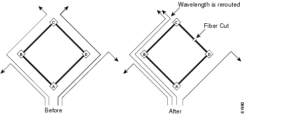
The ONS 15216 EDFA2 uses wavelength protection switching to restore wavelengths that are lost after a fiber cut. Figure 1-1 shows an example of wavelength protection switching. In this example, two wavelengths are routed clockwise around a metro ring, and two wavelengths are routed counter-clockwise around the same ring. Of the two clockwise wavelengths, only one transits the span linking locations C and D. If a fiber cut occurred on this span, the affected wavelength could be restored by rerouting it (counter-clockwise) around the ring to location D. Wavelength protection switching minimizes the amount of bandwidth allocated for restoration because only the affected wavelength is restored and not the entire fiber.
Figure 1-1 Wavelength Protection Switching
After a protection switch occurs, the number of wavelengths on each fiber changes. In the example, the number of counter-clockwise wavelengths increases to three, while the number of clockwise wavelengths decreases to one.
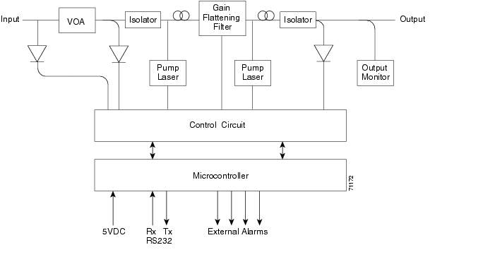
Figure 1-2 shows a block diagram of the ONS 15216 EDFA2.
Figure 1-2 Cisco ONS 15216 EDFA2 Block Diagram
Key Features
The ONS 15216 EDFA2 has the following key features:
•
Adjustable constant gain of 13 to 22 dBm
•
•
•
•
Constant Gain Mode
Constant amplification (gain) per wavelength is important for ensuring that variations in power between channels at the receivers is minimized. As wavelengths are added/dropped from an optical fiber, small variations in gain between channels in a span can cause large variations in the power difference between channels at the receivers. The ONS 15216 EDFA2 enables bandwidth-on-demand services by guaranteeing that every wavelength is amplified by a value that can be set between 13 and 22 dBm, no matter how many wavelengths are being amplified.
Constant gain mode is achieved using an automatic control circuit that adjusts pump power when changes in input power are detected. The ONS 15216 EDFA2 operates in constant gain mode by default, but since there may be applications where other operating modes may be required, the ONS 15216 EDFA2 can also be set to operate in any one the following modes:
•
•
•
Gain Flattening
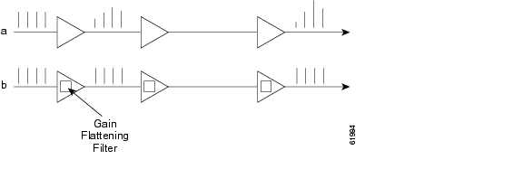
Figure 1-3 illustrates the importance of the gain flattening filter in the ONS 15216 EDFA2. As shown in the figure, with fiber (a), a set of channels with equal powers is input to a cascaded network of amplifiers that have vastly different power levels and optical signal-to-noise ratios (OSNR) at the output-without a gain flattening filter. In contrast, with fiber (b), the EDFAs effectively reduce this effect by introducing a gain flattening filter within each amplifier.
Figure 1-3 Gain Flattening Filter
Transient Suppression
Transients in the performance of optical amplifiers are inevitable whenever the number of signals, or the relative power of signals, changes. The ONS 15216 EDFA2 uses transient suppression to reduce the amount of time required by an amplifier to recover from a change. This indicates the suitability of the amplifier for add/drop applications like those described earlier.
Low Noise
Whenever there is gain in an optical system, noise also occurs. The predominant source of noise in EDFAs is amplified spontaneous emission (ASE). The ONS 15216 EDFA2 has a low noise figure of < 7 dB at -5 dBm input.
SNMP MIBs
The ONS 15216 EDFA2 SNMP MIB contains definitions of management information that allows network systems to be remotely monitored, configured, and controlled.
![]()
![]()
![]()
![]()
![]()
![]()
![]()
![]()
Posted: Sun Apr 2 12:21:45 PDT 2006
All contents are Copyright © 1992--2006 Cisco Systems, Inc. All rights reserved.
Important Notices and Privacy Statement.