|
|

Table Of Contents
Cisco ONS 15216 Dispersion Compensation Unit User Guide
Remove and Install the Dispersion Compensation Modules
Remove the Dispersion Compensation Modules
Install the Dispersion Compensation Modules
Remove and Install the Dispersion Compensation Unit Chassis
Remove and Install the Chassis Ground Strap
Install the Chassis Ground Strap
Fiber-Optic Connector Cleaning and Maintenance
Customer Supplied Cleaning Materials
Clean Fiber-Optic Cable Connectors
Clean the Internal Fiber-Optic Cable Connectors
Cisco Optical Networking Product Documentation CD-ROM
Cisco Product Security Overview
Reporting Security Problems in Cisco Products
Obtaining Technical Assistance
Cisco Technical Support & Documentation Website
Definitions of Service Request Severity
Obtaining Additional Publications and Information
Cisco ONS 15216 Dispersion Compensation Unit User Guide
The Dispersion Compensation Unit (DCU) is a complementary part of the Cisco ONS 15216 product family. The DCU can interoperate with the ONS 15454, ONS 155xx, and ONS 15600 products.
This user guide contains functional and physical descriptions of the DCU shelf assembly (chassis) and its Dispersion Compensation Modules, instructions for installing the DCU chassis into the rack-mounted ONS 15216 shelf, and instructions for installing modules into the DCU chassis.
Functional Description
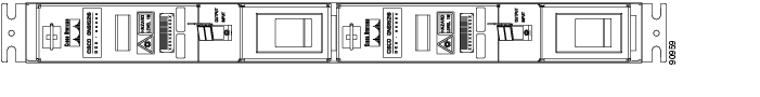
The DCU consists of the chassis and two modules. The modules function in both bidirectional and wavelength division multiplexing (WDM) directions. Figure 1 shows the front view of the DCU chassis with two modules installed.
Figure 1 Cisco ONS 15216 DCU Shelf Assembly (Front View)
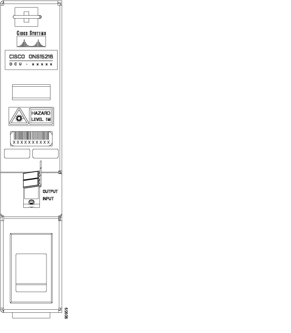
Figure 2 shows the front panel of a DCU module.
Figure 2 Cisco ONS 15216 Dispersion Compensation Module (Front View)
Module capacity is determined by the level of chromatic dispersion compensation (CDC) granularity. Table 1 describes the DCU module models available; they include seven C-band and six L-band models.
Module Function
In optical networks, the DCU provides compensation for accumulated chromatic dispersion effect in line and terminal sites. It provides a flexible solution for accumulated chromatic dispersion without dropping and regeneratating the wavelengths on the link, a process that would otherwise be necessary when accumulated chromatic dispersion exceeds the maximum allowed dispersion tolerance.
To provide effective compensation, the DCU is designed to operate over the entire band from 1525 to 1565 nm.
Two modules can be installed in the DCU chassis, one for east-to-west traffic and the other for west-to-east traffic. Each DCU chassis mounts into a 1-RU, 19-inch rack. A module consists of a fiber spool, connectors, and a connector adapter for input and output. The connector adapter has a cover that provides protection from laser radiation. The cover also protects against dirt and dust, which can cause equipment failure.
Connections
The DCU chassis has no connectors, but the DCU modules have one LC/UPC connector adapter. Table 2 describes the input connection.
Table 2 Dispersion Compensation Module Input Connection
LC-UPC type connector
LC-UPC/LC-PC connector
LC-UPC/LC-PC connector
Table 3 describes the output connection.
Table 3 Dispersion Compensation Module Output Connections
LC-UPC type connector
LC-UPC/LC-PC connector
LC-UPC/LC-PC connector
Technical Specifications
This section provides optical, environmental, and mechanical specifications for the DCU.
Optical Specifications
Table 4 lists the operating wavelengths.
Table 4 Dispersion Compensation Module Operating Wavelengths
Negative
C-band
1525—1565
1545.32
Environmental Specifications
Table 5 lists the environmental specifications for the DCU shelf assembly (chassis).
Table 5 DCU Chassis Environmental Specifications
Temperature
-5Α — 55ΑC (23Α to 131ΑF)
Relative Humidity
95% maximum, non-condensing
Mechanical Specifications
Table 6 lists mechanical specifications for the DCU module.
Remove and Install the Dispersion Compensation Modules
This section contains information for the removal and installation of the DCU modules, DCU chassis, and grounding.
Remove the Dispersion Compensation Modules
Use the following procedure to remove a DCU module:
Step 1
Place your right-hand thumb on the thumb-block located in the middle of the module.
Step 2
Step 3
Step 4
Step 5
Install the Dispersion Compensation Modules
Use the following procedure to install a DCU module:
Step 1
Step 2
Remove and Install the Dispersion Compensation Unit Chassis
Warning
Note
Remove the DCU Chassis
Use the following procedure to remove the DCU shelf assembly:
Step 1
Step 2
Step 3
Install the DCU Chassis
Use the following procedure to install a DCU shelf asssembly:
Step 1
Step 2
Step 3
Remove and Install the Chassis Ground Strap
When installing or removing the DCU chassis, you must connect the ground first and disconnect it last.
Remove the Chassis Grounding
Use the following procedure to remove the chassis ground:
Step 1
Step 2
Step 3
Install the Chassis Ground Strap
Use the following procedure to install the chassis ground strap:
Step 1
Step 2
Step 3
Fiber-Optic Connector Cleaning and Maintenance
Regular connector cleaning is required to maintain the performance of fiber-optic circuits. Before installing the fiber-optic cable, always perform the cleaning procedure for cable connectors described in the following section. Whenever possible, inspect each connector before making a connection.
Warning
Warning
Customer Supplied Cleaning Materials
The following cleaning materials are recommended but are not supplied with the DCU:
•
•
•
When cleaning a paired cable connector (bulkhead mating adapter), always clean the mating adapter first. If the mating adapter is properly maintained, meaning it is used with clean, defect-free fiber connectors and capped when not in use, it should not require cleaning. However, if you suspect the adapter is dirty, clean it by blowing the adapter with clean, dry, oil-free compressed air. Always keep unused adapter ports and fiber connectors capped with a clean dust cap.
Clean Fiber-Optic Cable Connectors
Step 1
Step 2
The design of the LC connector makes it difficult to clean the entire perimeter of the ferrule, because only a small portion close to the ferrule tip is accessible. Clean the tip of the ferrule and the entire accessible perimeter. Keep the fiber connector capped at all times when not in use.
Step 3
Step 4
Step 5
Note
Clean the Internal Fiber-Optic Cable Connectors
The connectors on the DCU modules are inside adapters and need special cleaning treatment because they are difficult to access. Use the following procedure to clean internal fiber-optic cable adapters:
Step 1
Step 2
Step 3
Obtaining Documentation
Cisco documentation and additional literature are available on Cisco.com. Cisco also provides several ways to obtain technical assistance and other technical resources. These sections explain how to obtain technical information from Cisco Systems.
Cisco.com
You can access the most current Cisco documentation at this URL:
http://www.cisco.com/techsupport
You can access the Cisco website at this URL:
You can access international Cisco websites at this URL:
http://www.cisco.com/public/countries_languages.shtml
Product Documentation DVD
The Product Documentation DVD is a comprehensive library of technical product documentation on a portable medium. The DVD enables you to access multiple versions of installation, configuration, and command guides for Cisco hardware and software products. With the DVD, you have access to the same HTML documentation that is found on the Cisco website without being connected to the Internet. Certain products also have .PDF versions of the documentation available.
The Product Documentation DVD is available as a single unit or as a subscription. Registered Cisco.com users (Cisco direct customers) can order a Product Documentation DVD (product number DOC-DOCDVD= or DOC-DOCDVD=SUB) from Cisco Marketplace at this URL:
http://www.cisco.com/go/marketplace/
Cisco Optical Networking Product Documentation CD-ROM
Optical networking-related documentation, including Cisco ONS 15xxx product documentation, is available in a CD-ROM package that ships with your product. The Optical Networking Product Documentation CD-ROM is updated periodically and may be more current than printed documentation.
Ordering Documentation
Registered Cisco.com users may order Cisco documentation at the Product Documentation Store in the Cisco Marketplace at this URL:
http://www.cisco.com/go/marketplace/
Nonregistered Cisco.com users can order technical documentation from 8:00 a.m. to 5:00 p.m. (0800 to 1700) PDT by calling 1 866 463-3487 in the United States and Canada, or elsewhere by calling 011 408 519-5055. You can also order documentation by e-mail at tech-doc-store-mkpl@external.cisco.com or by fax at 1 408 519-5001 in the United States and Canada, or elsewhere at 011 408 519-5001.
Documentation Feedback
You can rate and provide feedback about Cisco technical documents by completing the online feedback form that appears with the technical documents on Cisco.com.
You can submit comments about Cisco documentation by using the response card (if present) behind the front cover of your document or by writing to the following address:
Cisco Systems
Attn: Customer Document Ordering
170 West Tasman Drive
San Jose, CA 95134-9883We appreciate your comments.
Cisco Product Security Overview
Cisco provides a free online Security Vulnerability Policy portal at this URL:
http://www.cisco.com/en/US/products/products_security_vulnerability_policy.html
From this site, you will find information about how to:
•
•
•
A current list of security advisories, security notices, and security responses for Cisco products is available at this URL:
To see security advisories, security notices, and security responses as they are updated in real time, you can subscribe to the Product Security Incident Response Team Really Simple Syndication (PSIRT RSS) feed. Information about how to subscribe to the PSIRT RSS feed is found at this URL:
http://www.cisco.com/en/US/products/products_psirt_rss_feed.html
Reporting Security Problems in Cisco Products
Cisco is committed to delivering secure products. We test our products internally before we release them, and we strive to correct all vulnerabilities quickly. If you think that you have identified a vulnerability in a Cisco product, contact PSIRT:
•
An emergency is either a condition in which a system is under active attack or a condition for which a severe and urgent security vulnerability should be reported. All other conditions are considered nonemergencies.
•
In an emergency, you can also reach PSIRT by telephone:
•
•
Tip
Never use a revoked or an expired encryption key. The correct public key to use in your correspondence with PSIRT is the one linked in the Contact Summary section of the Security Vulnerability Policy page at this URL:
http://www.cisco.com/en/US/products/products_security_vulnerability_policy.html
The link on this page has the current PGP key ID in use.
If you do not have or use PGP, contact PSIRT at the aforementioned e-mail addresses or phone numbers before sending any sensitive material to find other means of encrypting the data.
Obtaining Technical Assistance
Cisco Technical Support provides 24-hour-a-day award-winning technical assistance. The Cisco Technical Support & Documentation website on Cisco.com features extensive online support resources. In addition, if you have a valid Cisco service contract, Cisco Technical Assistance Center (TAC) engineers provide telephone support. If you do not have a valid Cisco service contract, contact your reseller.
Cisco Technical Support & Documentation Website
The Cisco Technical Support & Documentation website provides online documents and tools for troubleshooting and resolving technical issues with Cisco products and technologies. The website is available 24 hours a day, at this URL:
http://www.cisco.com/techsupport
Access to all tools on the Cisco Technical Support & Documentation website requires a Cisco.com user ID and password. If you have a valid service contract but do not have a user ID or password, you can register at this URL:
http://tools.cisco.com/RPF/register/register.do
Note
Submitting a Service Request
Using the online TAC Service Request Tool is the fastest way to open S3 and S4 service requests. (S3 and S4 service requests are those in which your network is minimally impaired or for which you require product information.) After you describe your situation, the TAC Service Request Tool provides recommended solutions. If your issue is not resolved using the recommended resources, your service request is assigned to a Cisco engineer. The TAC Service Request Tool is located at this URL:
http://www.cisco.com/techsupport/servicerequest
For S1 or S2 service requests, or if you do not have Internet access, contact the Cisco TAC by telephone. (S1 or S2 service requests are those in which your production network is down or severely degraded.) Cisco engineers are assigned immediately to S1 and S2 service requests to help keep your business operations running smoothly.
To open a service request by telephone, use one of the following numbers:
Asia-Pacific: +61 2 8446 7411 (Australia: 1 800 805 227)
EMEA: +32 2 704 55 55
USA: 1 800 553-2447For a complete list of Cisco TAC contacts, go to this URL:
http://www.cisco.com/techsupport/contacts
Definitions of Service Request Severity
To ensure that all service requests are reported in a standard format, Cisco has established severity definitions.
Severity 1 (S1)—An existing network is down, or there is a critical impact to your business operations. You and Cisco will commit all necessary resources around the clock to resolve the situation.
Severity 2 (S2)—Operation of an existing network is severely degraded, or significant aspects of your business operations are negatively affected by inadequate performance of Cisco products. You and Cisco will commit full-time resources during normal business hours to resolve the situation.
Severity 3 (S3)—Operational performance of the network is impaired, while most business operations remain functional. You and Cisco will commit resources during normal business hours to restore service to satisfactory levels.
Severity 4 (S4)—You require information or assistance with Cisco product capabilities, installation, or configuration. There is little or no effect on your business operations.
Obtaining Additional Publications and Information
Information about Cisco products, technologies, and network solutions is available from various online and printed sources.
•
•
http://www.cisco.com/go/marketplace/
•
•
•
http://www.cisco.com/go/iqmagazine
or view the digital edition at this URL:
http://ciscoiq.texterity.com/ciscoiq/sample/
•
•
http://www.cisco.com/en/US/products/index.html
•
http://www.cisco.com/discuss/networking
•
![]()
![]()
![]()
![]()
![]()
![]()
![]()
![]()
Posted: Tue Apr 25 01:27:30 PDT 2006
All contents are Copyright © 1992--2006 Cisco Systems, Inc. All rights reserved.
Important Notices and Privacy Statement.