|
|

Table Of Contents
Cisco ONS 15200 Quick Installation Guide
Installation Materials for ONS 15200
Installation Materials for the ONS 15252
Installing the ONS 15252 in a 19-in. (485-mm) Rack
Installing Power and Ground to the ONS 15252 Fan Tray Assembly
Installing Power and Ground to the ONS 15252 Shelf
Installing Fiber on the ONS 15252 MCU
Installation Checklist for ONS 15252
Installation Materials for the ONS 15201
Mounting the ONS 15201 SCU in an Equipment Rack
Installing Power and Ground to the ONS 15201
Installing Fiber on the ONS 15201 SCU
Installation Checklist for ONS 15201
Quick Start Guide
Cisco ONS 15200 Quick Installation Guide
Applications with External DWDM Filters
Hardware Release 2.0
August 2002
1 Before Starting
This guide provides basic instructions for installing the Cisco ONS 15200 system. This ONS 15200 system is used for applications with external dense wavelength division multiplexing (DWDM) filters. This document contains two different parts:
•
Installing the ONS 15252 MCU and the ONS 15216 MUX/DEMUX.
•
Use this guide as a general reference when performing an installation.
For detailed installation instructions, refer to the most recent Cisco ONS 15200 Installation, Setup, and Test Manual (Hardware Release 2.0) and the ONS 15216 MUX/DEMUX and ONS 15216 Optical Add/Drop Multiplexer (OADM) documentation.
Warning
2 Power Disconnection Warning
3 Laser Radiation Warning
4 Installation Materials for ONS 15200
Several items are needed to complete the installation of the ONS 15200. Some of these items are supplied by Cisco and some need to be supplied by the user. The following are the Cisco-supplied materials; the number in parentheses is the quantity of each included item.
•
•
•
•
•
•
•
•
The following materials, tools, and equipment are recommended but are not supplied with the ONS 15200:
•
•
•
•
•
•
•
•
•
•
•
•
•
•
•
•
•
5 Installing the ONS 15252 MCU
To install the ONS 15252 Multichannel Unit (MCU), complete the following procedures:
1.
2.
3.
4.
Installation Materials for the ONS 15252
For details, see Installation Materials for ONS 15200.
Installing the ONS 15252 in a 19-in. (485-mm) Rack
The shelf assembly comes ready for installation in a 19-in. (485-mm) rack. The ONS 15252 is 19-in. (485-mm) wide by 11-in. (279-mm) deep by 21-in. (532-mm) high.
Note
Note
Step 1
Step 2
Step 3
Step 4
Step 5
Step 6
Step 7
Step 8
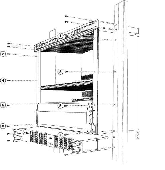
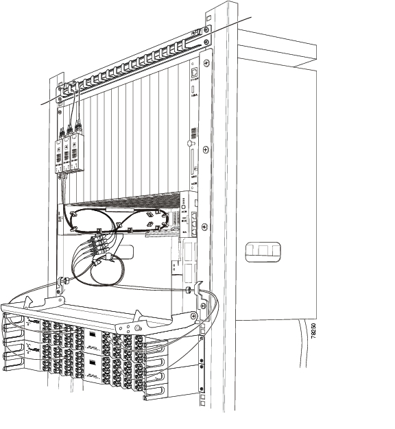
Figure 1 Install the ONS 15252 Shelf with the ONS 15252 Fan Unit and the ONS 15216 MUX/DEMUX in a 19-in. Rack
Installing Power and Ground to the ONS 15252 Fan Tray Assembly
Use the following procedure to install power and ground to the ONS 15252 fan tray assembly:
Step 1
Step 2
Step 3
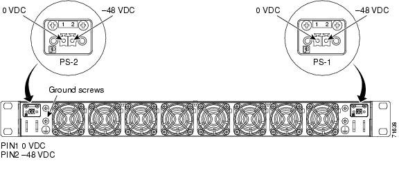
Figure 2 Installing Power and Ground to the ONS 15252 Fan Unit
Installing Power and Ground to the ONS 15252 Shelf
The power needs to be properly installed and grounded for operation of the ONS 15252. Use Figure 3 while completing the following procedure:
Warning
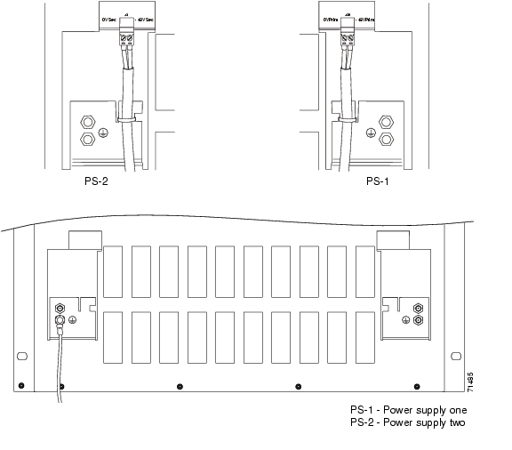
Figure 3 Installing Power and Ground to the ONS 15252
Caution
Step 1
Step 2
Note
Step 3
Step 4
Note
Installing Fiber on the ONS 15252 MCU
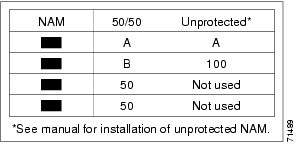
Transmit and receive fibers from the client side connect to the top connectors of the Client Layer Interface Port (CLIP). In protected mode, transmit and receive fibers from the DWDM side connect to the four bottom connectors of the Network Adapter Module (NAM) ( Figure 5). In protected mode, three transmit and receive fibers from the NAM connect to the bottom connectors of the CLIP. In unprotected mode, only two fibers connect to the CLIP.
Warning
Note
To avoid confusion in the future, label each end of the transmit and receive cables. To install the fiber patch cords, gently push the SC connector into the connector on the card until it snaps into place with a click.
For future use (in case of servicing) keep the dust caps in a clean location.
Note
Figure 4 NAM Connector Label
Routing Fiber Patch Cords
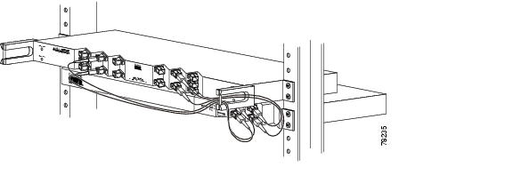
After connecting the fibers from the client side, route the fibers through the fiber organizer tray on the fan unit. After connecting the fibers from the ONS 15216 to the NAM (DWDM side), route the fibers through the holding device of the NAMs and route the fibers through the lateral fiber guide of the shelf. Wind the fibers to a loop with a diameter of approximately 3.15 in. (80 mm). Fix the fibers from each NAM with a strap and place them on the holding device of the NAM ( Figure 5).
Figure 5 Routing the Fiber in the ONS 15252 Shelf
Installation Checklist for ONS 15252
The following list is an installation checklist. Use this list as a reference when performing an installation. For detailed installation instructions, refer to the Cisco ONS 15200 Installation, Setup and Test Manual (Release 2.0). To check the installation, verify the following items:
•
•
•
•
•
•
•
•
•
•
•
•
•
•
Note
6 Installing the ONS 15201 SCU
To install the ONS 15252 Single-channel Unit (SCU), complete the following procedures:
1.
2.
3.
Installation Materials for the ONS 15201
For details, see Installation Materials for ONS 15200.
Mounting the ONS 15201 SCU in an Equipment Rack
The shelf assembly comes ready for installation in a 19-in. (485-mm) rack. The ONS 15201 is 19-in. (485-mm) wide by 11-in. (279-mm) deep by 1.8-in. (44.5-mm) high.
Step 1
Step 2
Step 3
Step 4
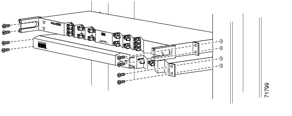
Figure 6 Install the ONS 15201 SCU and the ONS 15216 OADM
Installing Power and Ground to the ONS 15201
The power needs to be properly installed and grounded for operation of the ONS 15201. Use Figure 7 while completing the following procedure:
Warning
Warning
Figure 7 Installing Power and Ground to the ONS 15201
Step 1
Step 2
Step 3
Step 4
Note
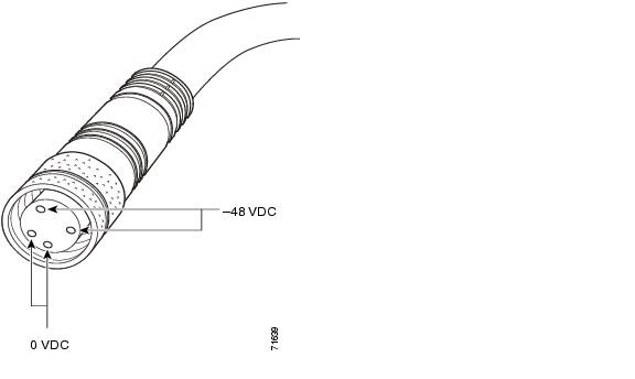
Figure 8 ONS 15201 SCU Power Cable Connector
Note
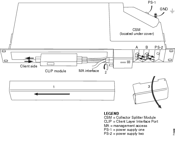
Installing Fiber on the ONS 15201 SCU
Transmit and receive fibers from the client side connect to the left connectors (behind the sliding cover) of the CLIP. Transmit and receive fibers from the DWDM side are preconnected.
To avoid confusion in the future, label each end of the transmit and receive cables. To install the fiber patch cords, gently push the connector into the adapter on the CLIP and on the SCU until it snaps into place with a click.
Warning
Note
For future use (in case of servicing) keep the dust caps in a clean location.
Routing Fiber Patch Cords
After connecting the fibers from the client side to the ONS 15201 SCU, route the fibers through the rack. After connecting the fibers between the ONS 15216 OADM and the ONS 15201 SCU (DWDM side), route the fibers through the fiber guides of the ONS 15216 OADM ( Figure 9).
Figure 9 Routing the Fiber in the ONS 15201 Shelf
Installation Checklist for ONS 15201
The following list is an installation checklist. Use this list as a reference when performing an installation. For detailed installation instructions, refer to the Cisco ONS 15200 Installation, Setup and Test Manual (Hardware Release 2.0).
To check the installation, verify the following items:
•
•
•
•
•
•
•
•
•
•
•
![]()
![]()
![]()
![]()
![]()
![]()
![]()
![]()
Posted: Thu Aug 30 06:53:22 PDT 2007
All contents are Copyright © 1992--2007 Cisco Systems, Inc. All rights reserved.
Important Notices and Privacy Statement.