|
|

This chapter describes the Collector Filter module (CFM).
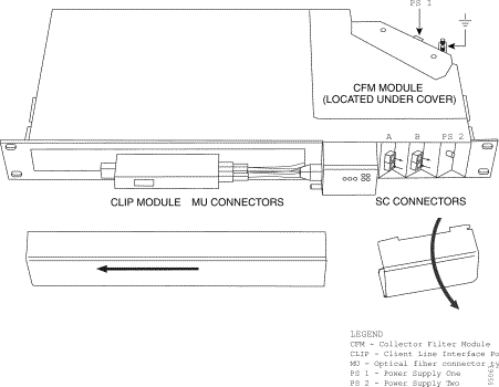
The CFM is used in dense wave division multiplexing (DWDM) systems. The CFM transfers optical signals between the DWDM side of the ONS 15201 Single-Channel Unit (SCU) and the Client Layer Interface Port (CLIP) module. It also transfers the part of the signal not intended for the SCU to the opposite port on the other side. Only one CFM is used in each collector node.
The CFM adds the output signal from the CLIP DWDM laser to the optical line. The CFM also drops the incoming signal from the same ITU channel. In protected mode, this signal goes to the A and B receivers on the collector CLIP module. In unprotected mode, this signal goes to the A receiver only; the B receiver is not mounted.
Channels that are not dropped by the CFM are passed through the SCU. Refer to Chapter 1 of the Cisco ONS 15200 Product Description for optical loss information.
If the wavelength is not stripped off and sent to the CLIP, the A-side IN goes to the B-side OUT, the B-side IN goes to the A-side OUT.
 |
Note No alarm or supervisory interconnections are used with the CFM. |
The following tables show how the CFM is connected to the SCU. For detailed optical hookup and testing procedures, refer to the Cisco ONS 15200 Installation, Setup, and Test Manual.
 |
Caution Remember to always clean the fiber optic connectors before inserting them into the adapters. |
Table 14-1 shows the placement of the SC connectors (numbered 1, 2, 3 and 4) for the different ONS 15201 SCU split ratios.
|
Note The CLIP Input B is never used in an unprotected system. |
The MU cables are connected on the front panel of the CLIP module. Table 14-2 explains how to connect the MU connectors (labeled A, B, 90, 10). The unlabeled optical fiber jumper cable transmits the dropped optical signal from the CFM to the CLIP module.
This section provides optical, environmental, and mechanical specifications for the CFM. Electrical specifications and default thresholds do not apply.
Table 14-3 specifies general operating conditions.
Table 14-4 lists optical operating frequencies.
For optical loss information, refer to Chapter 1 of the Cisco ONS 15200 Product Description.
CFM climatic limits during normal operation are listed in Table 14-5.
The Collector Filter module consists of the following parts:
The fiber type is 0.9-mm diameter SMF. The filters use SC and MU connectors. The coupler uses one MU connector. The two-fiber side of the coupler is always fusion spliced.
This section explains how to replace and remove the CFM. This module is used only in the ONS 15201 Single-Channel Unit (SCU).
|
Caution Be careful not to pull the optical fibers or make sharp bends in the fibers. Always clean and inspect the MU or SC connectors before inserting them into the adapters. |
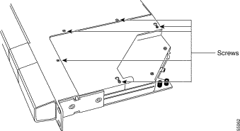
Step 2 Loosen the five screws on the right side (shown in Figure 14-2).
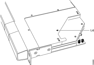
Step 3 Remove the lid.
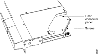
Step 4 Remove the two screws that hold the rear connector panel in place (shown in Figure 14-3).
Step 5 Remove the rear connector panel.
Step 6 Remove the left-front panel cover of the ONS 15201 SCU, as shown in Figure 14-4.
|
Note The SCU Front Panel illustration in Figure 14-4 shows A and B line connections on the front. Also shown is an optional rear placement of these connections. The rear connections may not be present on the equipment. |
Step 7 Remove the four retaining screws from the CFM.
Step 8 Disconnect the CFM optical connectors one at a time and put dust caps on them.
|
Caution Always put dust plugs on the adapters where the connectors were previously installed. |
Step 9 Carefully lift and remove the CFM from the ONS 15201 SCU.
Step 10 Replace the cover (if you do not plan to replace the CFM in the near future).
|
Caution Be careful not to bend the MU cables excessively during this procedure. |
Step 2 Make sure that the ribbon cable from the backplane lies flat on the bottom of the SCU and that it is stretched forward as much as possible.
|
Caution Be careful not to damage the optical fiber cables while inserting the module. |
Step 3 Carefully insert the CFM into the ONS 15201 SCU. Guide the MU connectors to come out on the front of the SCU.
Step 4 Align the four holes in the CFM case with the four module stand-offs located inside the ONS 15201 SCU. When properly aligned the module stand-offs will fit into the holes in the CFM case.
Step 5 Fasten the CFM to the module stand-offs with four retaining screws.
Step 6 Clean and inspect the optical connectors one at a time before they are connected.
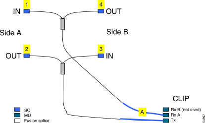
Step 7 Connect the CFM optical fiber jumper cables to the A-side and B-side adapters (SC to SC) in accordance with the labels located on the cables and Figure 14-5 through Figure 14-9.
|
Note For detailed instructions on connecting the CFM optical fiber, refer to the Cisco ONS 15200 Installation, Setup, and Test Manual. |
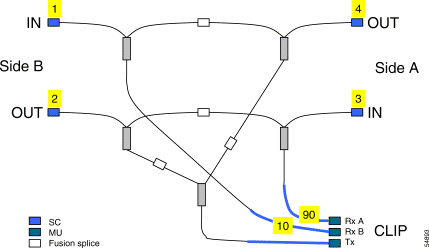
Figure 14-5 displays the connection information for the 90/10 optical signal split ratio.
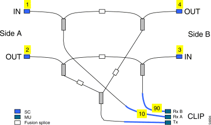
Figure 14-6 displays the connection information for the 10/90 optical signal split ratio.
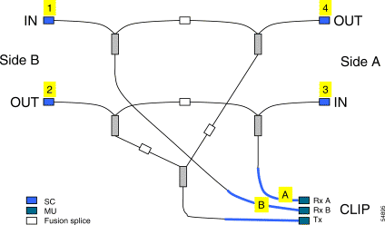
Figure 14-7 shows the 50/50 optical signal split ratio connections.
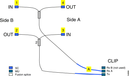
Figure 14-8 shows the 0/100 optical signal split ratio connections.
Figure 14-9 shows the 100/0 optical signal split ratio connections.
Step 8 Route the CFM to the CLIP module optical adapters through the opening in the front panel of the ONS 15201 SCU.
Step 9 Align the connector cover with its retaining screws.
Step 10 Install the connector cover by pushing down on it and sliding it forward.
Step 11 Using a slot or Phillips screwdriver, tighten the connector cover retaining screws.
Step 12 Align the CFM access lid with its retaining screws.
Step 13 Install the CFM access lid by pushing down on it and sliding it to the left.
Step 14 Using a slot or Phillips screwdriver, tighten the retaining screws on the CFM access lid.
![]()
![]()
![]()
![]()
![]()
![]()
![]()
![]()
Posted: Thu Apr 17 14:40:05 PDT 2003
All contents are Copyright © 1992--2002 Cisco Systems, Inc. All rights reserved.
Important Notices and Privacy Statement.