|
|

This chapter describes how to install the Maintenance Manager software and connect the ONS 15252 Multichannel Unit (MCU) or ONS 15201 Single-Channel Unit (SCU) to a laptop computer. For instructions on connecting to a desktop computer, contact the Cisco Technical Assistance Center (TAC) at 1-877-323-7368.
Before installing Maintenance Manager software, thoroughly review the prerequisites. This section explains the hardware and software requirements for successful installation.
Work should be completed in the following order:
Step 2 Shut down all applications.
Step 3 Install the Maintenance Manager.
The following minimum system requirements must be met before you can install Maintenance Manager software.
The following procedure describes how to install the Maintenance Manager software.
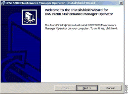
Step 2 After a few seconds, the ONS 15200 Maintenance Manager Operator - InstallShield Wizard window opens (Figure 1-1).
Step 3 Click Next. The License Agreement screen appears (Figure 1-2).
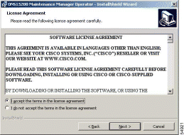
Step 4 Read the terms, and click I accept the terms in the license agreement.
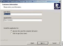
Step 5 Click Next. The Customer Information screen appears (Figure 1-3).
Step 6 Type the user name and organization in the appropriate boxes.
Step 7 Select Anyone who uses this computer (all users) or Only for me (Cisco user).
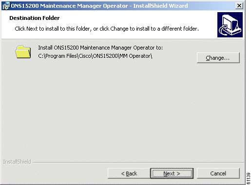
Step 8 Click Next. The Destination Folder Window appears (Figure 1-4).
Step 9 Select the folder where you want the Maintenance Manager software to reside. The default location is C:\Program Files\Cisco\ONS15200\MM Operator\. To choose a different location, click Change. After selecting the location, click Next.
Step 10 Click Next. The Ready to Install Window appears (Figure 1-5).
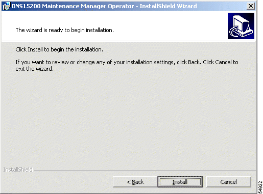
Step 11 Click Install. The Maintenance Manager begins installing. When installation is complete, a message will appear that says, "InstallShield Wizard Completed." Click Finish.
The procedure for installing the Maintenance Manager is complete.
The following sections describe how to connect a laptop computer running Maintenance Manager to an ONS 15200. Connection to the ONS 15200 must be made directly to either an MCU or an SCU. You cannot connect Maintenance Manager to the ONS 15200 indirectly using a local area network (LAN).
Restrictions determine which network elements (NEs) can be accessed based on the unit where the Maintenance Manager is physically connected. If the Maintenance Manager is connected to an SCU, you can only view information for the CLIP module installed in that SCU and its mate, which is assigned the same ITU channel, in another SCU or MCU. All other channels in the network are invisible. If the Maintenance Manager is connected to an MCU, you can see all the CLIP modules installed in that MCU and the mates of that MCU's CLIP modules.
The following procedure describes how to connect a laptop with Maintenance Manager to the ONS 15252 MCU. To connect to a desktop computer, contact the Cisco Technical Assistance Center (TAC) at 1-877-323-7368.
If this is the first time the CAN board is being installed in the computer, the hardware driver must be installed. Read the installation instructions included on the Maintenance Manager CD-ROM.
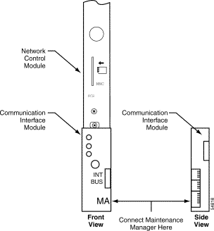
Step 2 Attach the RJ-45 connector at the end of the CCAN LINE connector cable to the Maintenance Access (MA) port on the Communications Interface module (CIM) (Figure 1-6). The CIM module is located below the Network Control Board (NCB) module in Slot 17 on the right side of the MCU. The MA connection on the CIM module is a standard RJ-45 connector.
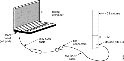
Step 3 Connect the DB-9 connector at the end of the MA CAN cable to the DB-9 connector at the end of the DRV CAN cable. The DRV CAN cable is the black cable with the large cylindrical component in the middle.
Step 4 On the laptop, connect the DRV CAN cable to the port located on the left side of the CAN board. Figure 1-7 illustrates the completed connection.
Step 5 When the two cables are connected from the laptop to the MA port, open Maintenance Manager. A "Loading Network Element Data" message appears and the Maintenance Manager main window opens.
The procedure for connecting the computer to the MCU is complete.
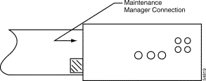
Step 2 Attach the RJ-45 connector at the end of the MA CAN connector cable to the Maintenance Manager connector on the SCU (Figure 1-8). The MA connection on the module is a standard RJ-45 connector.
Step 3 Using the DB-9 connector, connect the end of the DRV CAN cable to the DB-9 connector at the end of the CAN cable. The CAN cable is the black cable with the large cylindrical component in the middle.
Step 4 Connect the DRV CAN cable to the computer. The CAN cable connects to the PCMCIA connector on the CAN board. Figure 1-7 illustrates the completed connection.
Step 5 When the two cables are connected from the laptop to the MA port, open the Maintenance Manager. A "Loading Network Element Data" message appears and the Maintenance Manager main window opens.
The procedure for connecting the computer to the SCU is complete.
The following procedure describes how to uninstall the Maintenance Manager application.
Step 2 Choose the Maintenance Manager from the list.
Step 3 Click OK.
The procedure for uninstalling Maintenance Manager is complete.
To open the Maintenance Manager application:
Step 2 The Message Handler Log window opens followed by Maintenance Manager main window. The Message Handler Log window automatically minimizes.
The procedure for opening Maintenance Manager is complete.
To exit the Maintenance Manager program, choose Exit from the File menu.
![]()
![]()
![]()
![]()
![]()
![]()
![]()
![]()
Posted: Mon Jan 7 02:33:47 PST 2002
All contents are Copyright © 1992--2002 Cisco Systems, Inc. All rights reserved.
Important Notices and Privacy Statement.