|
|

This chapter provides preinstallation procedures for the Cisco ONS 15200. Chapter topics include shipment verification, site preparation, and equipment unpacking.
When you receive ONS 15200 system equipment at the installation site, immediately verify that the shipment is correct.
 |
Note Cisco does not recommend shipping equipment mounted in racks. To ship equipment from one site to another, pack the equipment in the original box. |
|
Note If you are storing the ONS 15200 prior to installation, keep the ONS 15200 system equipment in the original shipping containers. The storage period should not exceed 12 months. Store the packed equipment indoors in a well-ventilated and static-safe environment. |
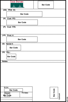
The ONS 15200 shipping container label provides specific information about the item being shipped. The label displays information in alphanumeric format followed by bar code format. Figure 2-1 shows a sample of a shipping container label.
Compare the packing list information with the alphanumeric information provided on the shipping labels. The packing list and shipping labels should contain the same information. If there are any discrepancies between the shipping label information and the packing list information, call the Cisco Technical Assistance Center (TAC) at 1-877-323-7368.
To report damage to shipped articles, contact the Cisco Technical Assistance Center (TAC) at 1-877-323-7368 to open a Return Material Authorization and Fault Symptom Report (RMA).
Verify that the installation site meets the following criteria:
The site conforms to all environmental specifications in the Cisco ONS 15200 Product Description.
The floor or mounting area where the equipment will be installed can support the equipment weight load. Table 2-1 lists the specific floor-loading requirements of the ONS 15200 system equipment.
|
Note The following tables are based on typical ONS 15200 system configurations. Floor loading, power consumption, heat dissipation, and clearances may vary in specific customer configurations. |
| Equipment Type | Floor Loading Requirements |
|---|---|
ONS 15252 MCU | 75 kg/m2 (15 lb/ft2) per ONS 15252 MCU |
ONS 15201 SCU | 8.6 kg/m2 (1.6 lb/ft2) per ONS 15201 SCU |
The installation site meets the power consumption requirements of the ONS 15200 equipment. Table 2-2 lists these requirements.
| Equipment Type | Power Consumption Requirements |
|---|---|
ONS 15252 MCU | 130 W |
ONS 15201 SCU | 8 W |
The installation location accommodates the heat dissipation requirements of the ONS 15200 equipment. Table 2-3 lists these requirements.
| Equipment Type | Heat Dissipation Requirements |
|---|---|
ONS 15252 MCU | 21 W/m2 per m of vertical frame space (6.5 W/ft2 per ft of vertical frame space) |
ONS 15201 SCU | 346.2 W/m2 per m of vertical frame space (9.793 W/ft2 per ft of vertical frame space) |
Minimum recommended clearance is provided for accessing bays from the front and back, opening front covers, and clearing the top of the racks. Table 2-4 provides clearance requirements.
| Item | Clearance Required |
|---|---|
Bay access needed for maintenance | Front access only, 482 mm (19 in.) |
Back clearance to bays | 15 cm (6 in.) |
Clearance to open equipment covers | 16 cm (6.4 in.) |
Consider the following when unpacking and storing ONS 15200 equipment:
The following procedures contain specific instructions for unpacking ONS 15200 system equipment.
 |
Caution When opening a subrack container, use caution to avoid damaging the contents. |
|
Caution Static electricity can damage electro-optical equipment. While unpacking and handling optical and electrical modules, wear a grounding wrist strap to discharge the static buildup. Before unpacking and installing modules or making system interconnections, connect the grounding wrist strap. The grounding wrist strap is designed to prevent equipment damage caused by static electricity. |
Step 2 Lift the cardboard top tray with all of its subpackages out of the MCU shipping container.
 |
Warning A fully-equipped ONS 15252 MCU with packaging weighs 37 kg (82 lb.). Two people must lift an ONS 15252 MCU; failure to do so may cause personal injury. |
Step 3 Remove the top protection of the MCU from the main cardboard container.
Step 4 Take out the entire MCU and remove the bottom protection and the plastic protection bag.
The MCU shipping container should contain the following items:
|
Caution When opening a subrack container, use caution to avoid damaging the contents. |
|
Caution Static electricity can damage electro-optical equipment. While unpacking and handling optical and electrical modules, wear a grounding wrist strap to discharge the static buildup. Before unpacking and installing modules or making system interconnections, connect the grounding wrist strap. The grounding wrist strap is designed to prevent equipment damage caused by static electricity. |
Step 2 Take the box containing the ONS 15201 SCU accessory kit out of the shipping container.
Step 3 Lift the ONS 15201 SCU packaging box and strip the inserts away. Open the packaging box.
Step 4 Lift the SCU out of the packaging box and remove the plastic protective bag.
The ONS 15201 SCU shipping container should contain the following items:
|
Caution When opening a module container, use caution to avoid damaging the contents. |
|
Caution Static electricity can damage electro-optical equipment. While unpacking and handling optical and electrical modules, wear a grounding wrist strap to discharge the static buildup. Each subrack is equipped with grounding wrist strap connectors. Before unpacking and installing modules or making system interconnections, connect the grounding wrist strap. The grounding wrist strap is designed to prevent equipment damage caused by static electricity. |
Step 2 Carefully remove the protective foam packing material from the module(s).
Step 3 If any optical adapters are included in the container, remove and save them for use during installation of the module front-panel optical fiber jumper cables ("Installation").
![]()
![]()
![]()
![]()
![]()
![]()
![]()
![]()
Posted: Sat Jan 5 12:34:51 PST 2002
All contents are Copyright © 1992--2002 Cisco Systems, Inc. All rights reserved.
Important Notices and Privacy Statement.