|
|

This chapter describes the components required for operation, administration, and maintenance of the Cisco ONS 15200.
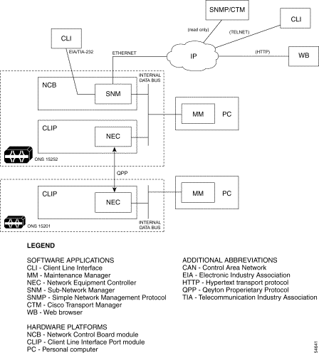
The ONS 15200 is supervised, administered, and monitored from the Network Control Board (NCB) module. In addition to controlling all of the ONS 15200 system Client Layer Interface Port (CLIP) modules, the NCB module collects information about system status, alarms, parameters, and actions on the internal data bus. See the "Alarms" section for a description of NCB alarms.
An ONS 15200 network can be managed using three different connection interfaces:
The three network management interface connections are illustrated in Figure 4-1.
You can control the ONS 15200 system using the Subnetwork Manager (SNM) software package running on the NCB module located in the ONS 15252 MCU. Access the SNM through either the EIA/TIA-232 port or the Ethernet port on the front of the NCB module. Additionally, you can manage the ONS 15200 system externally using the Command Line Interface (CLI) software package described in the "Command Line Interface" section or using the Maintenance Manager (MM) software package described in the "Maintenance Manager" section. With the Internet, you can manage the ONS 15200 system using the Web-based interface described in the "Web-Based Interface" section.
An NCB module and different CLIP modules of an ONS 15252 MCU are connected with an internal data bus (i.e., a CAN). This data bus can be extended over several co-located network elements (ONS 15252 MCUs or ONS 15201 SCUs) to a larger logical unit. The ONS 15201 SCU uses the same data bus as the MC. Normally all ONS 15200 equipment located at one site will be connected onto one CAN bus. Communication between the two end-points of a channel is carried optically over a proprietary protocol, QPP. Any CLIP module controlled by an NCB must not be more than two slots away from that NCB. If the CLIP is farther away from the NCB, additional NCB modules must be installed.
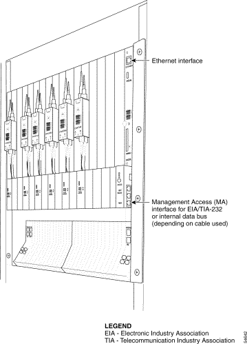
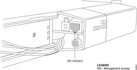
The EIA/TIA-232 port provides access to the SNM software running on the NCB module. The port is located at the ONS 15252 MCU management access (MA) interface connector on the CIM. The EIA/TIA-232 port is present on two pins of the MA interface; therefore, access to the EIA/TIA-232 using the EIA/TIA-232 cable that is included with the ONS 15252 MCU. You only need the EIA/TIA-232 interface to the NCB module when you are setting the initial IP address of the NCB module for the first time. After you have set the IP address, you can communicate with the NCB module via IP through the Ethernet port located on the front of the module. EIA/TIA-232 interface access and Ethernet access to the ONS 15252 MCU are illustrated in Figure 4-2. Additionally, once you have assigned an IP address to the NCB module, you can send information to the NCB module by file transfer protocol (FTP). Set the EIA/TIA-232 interface to the parameters listed in Table 4-1. Set the terminal settings to the parameters in Table 4-2.
| Parameter | Value |
|---|---|
Speed | 19.2 Kb/s |
Data Bits | 8 |
Parity | None |
Stop Bits | 1 |
Flow Control | None |
| Parameter | Value |
|---|---|
ASCII | Send line end with line feed |
The SNM software package Command Line Interface (CLI) is a simple, interactive tool that can be used to manage the ONS 15200 system.
The CLI interface resides on the NCB module and operates on the database server for the ONS 15200 system. Users are categorized in three categories: administrator, operator, and guest. Access is granted according to the defined rights of each category. Access rights to the CLI interface are granted via user name and password.
The privileges assigned to the different categories of users are:
The CLI interface has two modes of access for users—read-and-write access and read-only access. Access the CLI interface via the Ethernet port on the NCB module or via the MA interface on the CIM module. The MA interface access requires a EIA/TIA-232 cable.
The Maintenance Manager (MM) interactive software tool, installed on a laptop or PC, provides local craft interface to the ONS 15200 system. The MM software provides access to the internal data bus at ONS 15252 MCUs or ONS 15201 SCUs. It also provides a way to access data from the ONS 15200 network from isolated ONS 15201 SCUs.
In addition to the required cabling, a laptop must have a CAN Personal Computer Memory Card International Association (PCMCIA) board to use the MM software package as a local craft interface.
Connect your MM-equipped computer to the ONS 15200 system through the Management Access (MA) port as shown in the following figures. Figure 4-2 shows the management access connection to an ONS 15252 MCU. Figure 4-3 shows the management access connection to an ONS 15201 SCU.
The web-based interface allows read-only access to the ONS 15200 system data from any valid IP address. The NCB module must have a defined IP address and the user must log into the SNM software package running on the NCB module before web-based interface gaining access.
 |
Note The web-based interface does not function with Internet Explorer 4.0. |
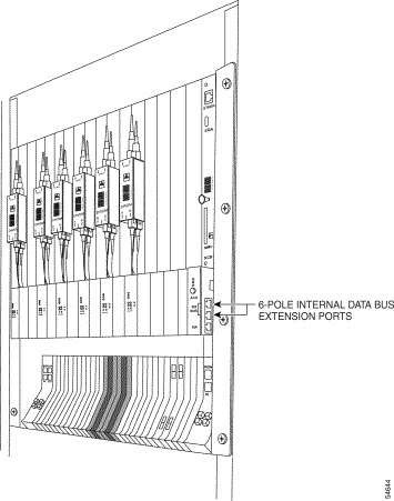
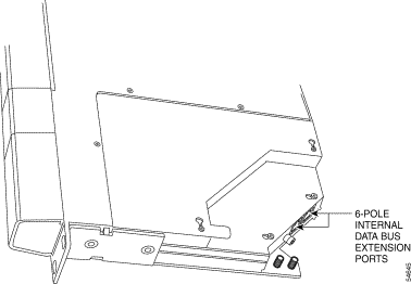
The controller area network (CAN) bus is a serial communications protocol interface bus that allows you to connect several ONS 15200 systems to create a more powerful network element. The CAN bus supports distributed real-time, secure control. There are two data bus extension ports located on the ONS 15252 MCU (shown in Figure 4-4). Additionally, there are two data bus extension ports located on the ONS 15201 SCU (shown in Figure 4-5).
The simple network management protocol (SNMP) interface allows read-only access to the ONS 15200 system data. For SNMP access, the NCB module must have an assigned IP address and a valid community name. The SNMP interface supports simple network management protocol versions 1 and 2c.
In the ONS 15200 Web Interface, the Alarms screen shows alarms recorded for all of the modules installed in the network. Table 4-3 describes the CLIP module alarms, Table 4-4 describes alarm status parameters, and Table 4-5 defines the on-screen colors displayed next to the alarm status.
| Condition Name | Definition |
|---|---|
DWDM_RXPOWER (unprotected only) | Power input from the A-side of the ONS 15200 network is outside the acceptable power range. |
DWDM_ARXPOWER | Power input from the A-side of the ONS 15200 network is outside the acceptable power range. |
DWDM_BRXPOWER | Indicates that the power input from the B-side of the ONS 15200 network is outside the acceptable power range. |
DWDM_PELTIERCURRENT | Peltier current of the selected CLIP module is outside the acceptable power range. |
DWDM_LASERTEMP | Temperature of the laser transmitting to the ONS 15200 network is outside the acceptable temperature range. |
CLIENT_RXPOWER | Power input from the client equipment is outside the acceptable power range. |
CLIENT_LASERTEMP | Temperature of the laser transmitting to the client equipment is outside the acceptable temperature range. |
ENVIRON_BOARDTEMP | Temperature on the surface of the CLIP module circuit board is outside the acceptable temperature range. |
| Alarm Name | Definition |
|---|---|
QPP (unprotected only) | Proprietary protocol error on the A-side of the network. |
QPPA | Proprietary protocol error on the A-side of the network. |
QPPB | Proprietary protocol error on the B-side of the network. |
CAN | Error on the CAN bus. |
POWER1 | PPS-1 input is outside of the acceptable range. |
POWER2 | PS-2 input is outside of the acceptable range. |
| Alarm Name | Definition |
|---|---|
Red | Critical or major alarm |
Yellow | Minor alarm or warning |
Green | Power on |
![]()
![]()
![]()
![]()
![]()
![]()
![]()
![]()
Posted: Mon Sep 30 20:44:08 PDT 2002
All contents are Copyright © 1992--2002 Cisco Systems, Inc. All rights reserved.
Important Notices and Privacy Statement.