|
|

The following paragraphs describe some of the Cisco ONS 15200 network configurations and a client-layer protection configuration. All modules mentioned in this chapter are described in more detail in "Module Descriptions."
The ONS 15200 is designed to operate in several network configuration arrangements. All ONS 15200 configurations consist of one or more ONS 15252 Multichannel Units (MCU) or ONS 15201 Single-Channel Units (SCUs). The following paragraphs describe some standard ONS 15200 network configurations, including:
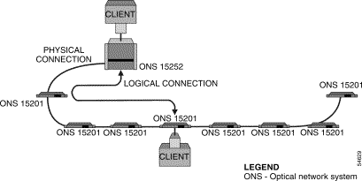
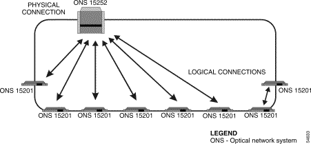
In an ONS 15200 system bus configuration, wavelength channels are allocated between an ONS 15252 MCU and several ONS 15201 SCUs. This configuration can be used only in networks where optical-layer fiber protection is unnecessary. It is possible to configure the bus configuration for layer 3 load-sharing protection or client-layer 1+1 automatic protection switching (APS), but the two data traffic flows would need to share the same optical-fiber cable path, and therefore protection would be incomplete.
In the bus configuration, all information exchange is between the Client Layer Interface Port (CLIP) modules located in the ONS 15252 MCU and the CLIP modules located in each ONS 15201 SCUs. Figure 2-1 illustrates the ONS 15200 system bus configuration.
 |
Note The physical connection in Figure 2-1 consists of two fiber-optic cables. |
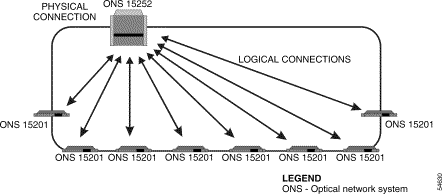
In the ONS 15200 ring configuration, wavelength channels are allocated between an ONS 15252 MCU and several ONS 15201 SCUs. Information is exchanged between a CLIP module installed in the ONS 15252 MCU and an associated CLIP module installed in an ONS 15201 SCU.
The ring configuration can be installed with or without fiber-optic protection. The ring configuration supports SONET or SDH ring protection and 1+1 APS client-layer protection. It is also possible to arrange the ring configuration to use layer 3 load sharing. Figure 2-2 illustrates the ring configuration with hubbed traffic.
 |
Note The physical connection in Figure 2-2 consists of two fiber-optic cables. |
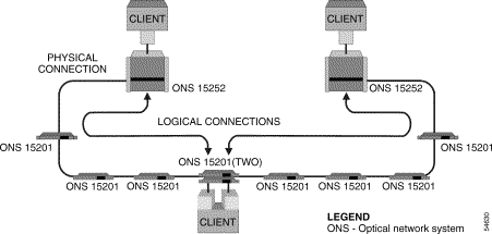
In the dual-home configuration, the total data traffic load is shared between two different fiber-optic cable routes from a pair of ONS 15201 SCUs. The pair of ONS 15201 SCUs can use identical or different wavelength channels to communicate with their respective home ONS 15252 MCUs. The use of identical wavelength channels conserves network resources. In addition to load sharing, the dual-home configuration provides traffic protection in the electronic client-layer domain. If one fiber-optic route is lost, the data traffic is directed to the other fiber-optic route in the client layer.
In addition to protecting traffic at the client layer, the dual-home configuration protects the ONS 15200 system against single ONS 15200 unit failures. Figure 2-3 illustrates the ONS 15200 dual home configuration.
 |
Note The physical connection in Figure 2-3 consists of two fiber-optic cables. |
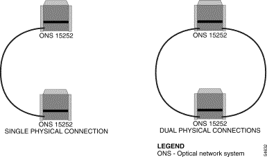
In the ONS 15200 multichannel, point-to-point configuration, multiple wavelength channels are allocated between a pair of ONS 15252 MCUs. The multichannel point-to-point configuration can be configured with or without optical-layer protection. Configuring optical-layer protection requires dual optical-fiber routes.
In the ONS 15200 multichannel, point-to-point configurations, dual optical-fiber routes are used to send information along two separate optical-fiber routes. The dual physical route configuration supports SONET or SDH add/drop multiplexer (ADM) protection and client-layer 1+1 APS protection. Layer 3 load-sharing protection can be implemented in the multichannel point-to-point configuration, but is not recommended. The two network fiber-optic routes would have to share an ONS 15252 MCU, and any failure of the ONS 15252 MCU would cause both routes to disappear simultaneously. Figure 2-4 illustrates the ONS 15200 multichannel, point-to-point configurations.
 |
Note The physical connection in Figure 2-4 consists of two optical fiber cables. |
In the ONS 15200 ring configuration with hubbed and meshed traffic, two ONS 15201 SCUs can be configured to communicate with each other, either in a direct point-to-point configuration via a control area network (CAN) bus connection as shown in Figure 2-5, or through a noninterfering ONS 15252 MCU. The ONS 15252 MCU must have a Bridge module (BM) installed.
The mesh configuration requires that the Maintenance Manager (MM) software and associated hardware be installed to manage the meshed channel. Alternatively, one of the ONS 15201 SCUs of the meshed channel can be connected to the ONS 15252 MCU with a CAN bus extension cable. An ONS 15201 SCU connected in this way will be on the same logical CAN bus as the ONS 15252 MCU.
In the mesh configuration, SONET or SDH ADM ring protection can be configured on the client side of the meshed channel. If client-layer 1+1 APS protection is implemented, each of the ONS 15201 SCUs would have to be replaced by a pair of ONS 15201 SCUs transmitting in opposite directions. Figure 2-5 illustrates the ONS 15200 ring configuration with hubbed and meshed traffic.
 |
Note The physical connection in Figure 2-5 consists of two optical fiber cables. |
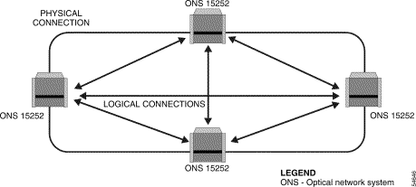
In the ONS 15200 full-mesh configuration, all units are configured to communicate with each other.
The full-mesh configuration can be managed by a single Network Control Board (NCB) module located in one of the ONS 15252 MCUs. The NCB module in the other ONS 15252 MCUs is replaced by an NCB front cover.
In the full-mesh configuration, SONET or SDH ADM ring protection can be configured on the client side of the two units, but layer 3 load sharing is not supported. If client-layer 1+1 APS protection is implemented, each of the units would need to be replaced by a pair of units transmitting in opposite directions of the ring. Figure 2-6 illustrates the ONS 15200 full-mesh configuration.
 |
Note The physical connection in Figure 2-6 consists of two optical fiber cables. |
![]()
![]()
![]()
![]()
![]()
![]()
![]()
![]()
Posted: Mon Sep 30 20:44:13 PDT 2002
All contents are Copyright © 1992--2002 Cisco Systems, Inc. All rights reserved.
Important Notices and Privacy Statement.