|
|

Table Of Contents
Network Element Management Interface (NEMI) and Device Element Management Interface (DEMI)
Network Element Management Interface (NEMI) and Device Element Management Interface (DEMI)
This chapter describes the Network Element Management Interface (NEMI) and the Device Element Management Interface (DEMI), and includes the following sections:
•
Overview
•
•
Overview
The Network Element Management Interface (NEMI) and the Device Element Management Interface (DEMI) modules provide the Cisco Metro 1500 series system with network connection and system management capabilities. This chapter describes the hardware elements and basic installation steps. See "Connecting the NEMI and the DEMI" for connection procedure information.
NEMI
The Network Element Management Interface (NEMI) is a two-slot module that is installed in the primary chassis of an 8 to 16 channel system. The NEMI functions under version 2.0.35 of the Linux operating system.The NEMI provides the following:
•
•
•
Systems with 24 to 32 Channels require the installation of a second NEMI module in extension chassis B. When the two NEMI modules are interconnected using an Inter-NEMI Network Connection (INNC), one NEMI module is configured as the NEMI-Master, while the second is configured as the NEMI-Slave.
Note
NEMI Placement
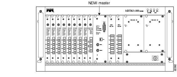
The placement location of the NEMI module (either Master or Slave) in the chassis is the same. See Figure 2-1.
Figure 2-1 NEMI Placement in the Primary Chassis and Extension Chassis B
NEMI Ports
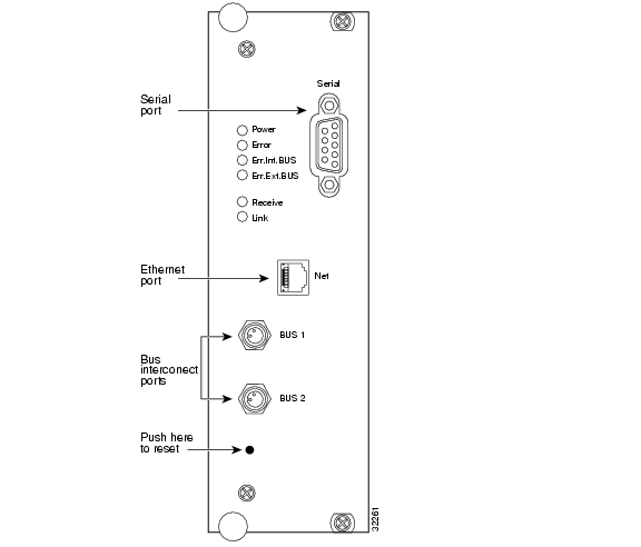
Each NEMI module contains four ports:
•
•
•
The ethernet port can be used to connect the NEMI to the network or to another computer. The serial port can be used to connect the NEMI to a computer for initial system configuration using PPP, for connection to modems or terminal servers, or for interconnecting two NEMI modules.
The bus interconnect ports are used to interconnect the NEMI-Master or the NEMI-Slave with the corresponding DEMI using external bus cables. The front panel of the NEMI is shown in Figure 2-2.
Figure 2-2 NEMI Front Panel
NEMI LEDs
Table 2-1 describes the functions of the LEDs shown in Figure 2-2.
NEMI Installation Procedure
Use the following procedures to install the NEMI.
Warning
To install the NEMI module (Master or Slave), follow these steps:
Step 1
Step 2
Figure 2-3 NEMI Placement in the Primary Chassis and Extension Chassis B
Step 3
Caution
Step 4
Step 5
Step 6
DEMI
The Device Element Management Interface (DEMI) is a single slot module that is installed in extension chassis A of a 16 Channel system. The DEMI module provides the following:
•
•
Systems with 24 to 32 channels require the installation of a second DEMI in extension chassis C.
The DEMI module in extension chassis A connects to the NEMI-Master module in the primary chassis. The DEMI module in extension chassis C connects to the NEMI-Slave module in extension chassis B.
DEMI Placement
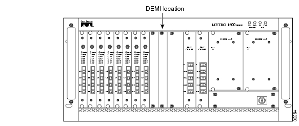
The placement location of the DEMI module is shown in Figure 2-4.
Figure 2-4 DEMI Placement in an Extension Chassis
DEMI Ports
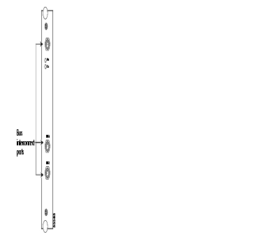
Each DEMI contains three bus interconnect ports. The ports are labeled BUS1 and BUS2. They are provided for interconnecting the DEMI to a NEMI using an external bus cable.
The unlabeled bus interconnect port at the top of the DEMI module is not currently implemented. Figure 2-5 shows the front panel of the DEMI.
Figure 2-5 DEMI Front Panel
DEMI LEDs
Table 2-2 describes the functions of the LEDs shown in Figure 2-5.
Table 2-2 LED Function Description
On
Power on
Green
On if the DEMI is powered up.
Err
Error
Red
On if any error is occurring.
DEMI Installation Procedure
Use the following procedures to install the DEMI.
Warning
To install the DEMI module, follow these steps:
Step 1
Step 2
Figure 2-6 DEMI Placement in Extension Chassis A and C
Step 3
Caution
Step 4
Step 5
![]()
![]()
![]()
![]()
![]()
![]()
![]()
![]()
Posted: Tue Apr 26 06:00:35 PDT 2005
All contents are Copyright © 1992--2005 Cisco Systems, Inc. All rights reserved.
Important Notices and Privacy Statement.