|
|

Table Of Contents
DWDM in Metropolitan Area Networks
Technologies in the Metropolitan Market
Applications and Services in the MAN
Topologies and Protection Schemes for DWDM
Practical Considerations in Deploying DWDM
DWDM in Metropolitan Area Networks
The long distances made possible by advances in technologies such as optical amplifiers, dispersion compensators, and new fiber types, resulted in the initial deployment of DWDM technology in the long-haul transoceanic and terrestrial networks. Once these technologies became commercially viable in the long-haul market, it was the next logical step to deploy them in the metropolitan area and, eventually, in the access networks using hybrid architectures of fiber and coaxial media.
We begin the following discussion by considering the main transport and network technologies used in metropolitan networks. We then briefly explore some of the potential applications for DWDM in these networks and examine the topologies that can be deployed. We continue by examining the protection mechanisms and schemes that are available to ensure reliability, and we conclude with a look at the future of optical networking.
Technologies in the Metropolitan Market
Numerous technologies for transport and encapsulation of data have been advocated in the metropolitan market. A characteristic of these networks, as noted earlier, is that they are called upon to support a variety of older and new traffic types and rates. Overall, however, there is a trend toward using a common optical layer for transporting digital data.
SONET/SDH
SONET/SDH has been the foundation for MANs over the last decade, serving as the fundamental transport layer for both TDM-based circuit switched network and most overlay data networks. While SONET/SDH has evolved into a very resilient technology, it remains fairly expensive to implement. Inherent inefficiencies in adapting data services to the voice-optimized hierarchy and an inflexible multiplexing hierarchy remain problematic. More importantly, capacity scaling limitations—OC-768 may be the practical limit of SONET/SDH—and unresponsiveness to bursty IP traffic make any TDM-based technology a poor choice for the future.
ATM
Many service providers favor ATM because it can encapsulate different protocols and traffic types into a common format for transmission over a SONET infrastructure. Meanwhile the data networking world, which is overwhelmingly IP-oriented, favors packet over SONET (POS), which obviates the costly ATM intermediate layer. Advancements in IP, combined with the scaling capacity of gigabit and multigigabit routers, make it possible to envisage an IP-based network that is well suited for carrying primarily data traffic, and secondarily voice.
Nevertheless ATM remains strong in the metropolitan area. It can accommodate higher speed line interfaces and provide managed virtual circuit services while offering traffic management capabilities. Thus ATM edge devices are commonly used to terminate traffic, including VoIP, DSL, and Frame Relay.
Gigabit Ethernet
Gigabit Ethernet (GE) is a proven technology for easy migration from and integration into traditional Ethernet. It is relatively inexpensive compared to other technologies that offer the same transmission rate, but does not provide quality of service (QoS) or fault tolerance on its own. When confined to point-to-point topologies, collisions and carrier sense multiple access (CSMA) are not of concern, resulting in more effective use of the full bandwidth. Because the optical physical layer can support much longer distances than traditional Category 5 cable, Gigabit Ethernet over fiber (1000BASE-LX, for example) can be extended into the wide-area realm using DWDM.
The latest advancement in Ethernet technology, 10 Gigabit Ethernet, is being driven by a need to interconnect Ethernet LANs operating at 10, 100, or 1000 Mbps. Ten Gigabit Ethernet can be used for aggregating slower access links, in the backbone networks, and for WAN access. Using 1550-nm serial lasers, distances of 40 to 80 km (25 to 50 mi) are possible with 10 Gigabit Ethernet over standard SM fiber. With such technology, service providers can build simple Ethernet networks over dark fiber without SONET or ATM and provision high-speed 10/100/1000 Mbps services at very low cost. In addition, a very short reach (VSR) OC-192 interface can be used to connect 10 Gigabit Ethernet to DWDM equipment over MM fiber.
Ethernet offers the technical advantages of a proven, adaptable, reliable, and uncomplicated technology. Implementations are standard and interoperable, and cost is much less than SONET or ATM. Architecturally, Ethernet's advantage is its emerging potential to serve as a scalable, end-to-end solution. Network management can also be improved by using Ethernet across the MAN and WAN.
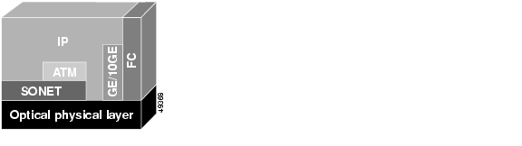
IP
Clearly, as traditional circuit-switched services migrate to IP networks and data grows, networks must evolve to accommodate the traffic. However, IP may need to become as complex as ATM to replace its functionality. Thus, both ATM and IP are candidates for transport directly over DWDM. In either case, the result is simplified network infrastructure, lower cost due to fewer network elements and less fiber, open interfaces, increased flexibility, and stability. The question is, in which format will IP travel over an optical network: IP over ATM over SONET, IP over SONET (as POS), or IP over Gigabit Ethernet or 10 Gigabit Ethernet? (See Figure 3-1.)
Figure 3-1 Data Link and Network Protocols over the Optical Layer
Fibre Channel
Fibre Channel is the predominant data link technology used in storage area networks (SANs). See the "Storage Area Networks" section. Fibre Channel is an economical replacement for the Small Computer System Interface (SCSI) protocol as a high-speed interface for applications such as data backup, recovery, and mirroring. Fibre Channel interfaces are available at 100 MBps today; 200 MBps interfaces should be available in the near future, and 400 MBps interfaces are in testing.
Note
By convention, transfer rates for storage are specified in megabytes per second (MBps).
Fibre Channel comes without the very short distance limitations of SCSI; it also avoids the termination restrictions of SCSI because each node acts as an optical repeater. Fibre Channel can be implemented in a point-to-point, arbitrated loop, or mesh topology using a switch. As shown in Figure 3-1, Fibre Channel, like other protocols, can be carried directly over the optical layer using DWDM.
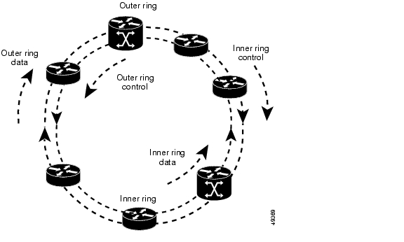
Dynamic Packet Transport
Dynamic Packet Transport (DPT) is a Cisco protocol that provides an alternative to SONET for more efficient transport of data in ring architectures. DPT supports basic packet processing, fairness, multicasting, Intelligent Protection Switching (IPS), topology discovery, Address Resolution Protocol (ARP), routing, and network management. DPT can run over dark fiber, SONET, or WDM.
DPT's chief advantage over SONET is its ability to reuse bandwidth that would have otherwise been lost. Bandwidth is consumed only on traversed segments, and multiple nodes can transmit concurrently.
DPT is based on bidirectional counter rotating rings (see Figure 3-2). Packets are transported on both rings in concatenated payload, while control messages are carried in the opposite direction from data.
Figure 3-2 DPT Ring Architecture
FDDI
FDDI is at this point a legacy technology. Having served a need at one time, it has been replaced by more advanced technologies. Although FDDI is capable of scaling to the metropolitan area, it is also a shared media technology with a relatively low capacity by current standards. This limitation, along with falling availability of FDDI interfaces on network equipment, is causing FDDI to be replaced by Gigabit Ethernet, or ATM. Nevertheless, it is also a protocol that can be transparently transported over the optical layer using DWDM.
Support for Legacy Traffic
In spite of the disproportionate growth of data traffic versus voice, legacy traffic won't suddenly vanish. Networks must support diverse low speed connections in addition to newer, higher speed data connection. Thus DWDM must be complimented by electrical (TDM/FDM) multiplexing to ensure efficient use of lightwaves. At the same time, legacy traffic must be augmented with high-capacity data transport without impacting efficient IP transport.
For ISPs, the situation is different: All of their traffic is IP. ISPs need rapid build-out of networks and favor packet-over-lightwave or Gigabit Ethernet, rather than ATM or SONET. Other requirements of this market include load sharing strategies for resilience, leverage of dark fiber, and simpler datacom-like management.
Applications and Services in the MAN
The metropolitan network market is being driven by demand for new application services and the introduction of high speed access. Taken together, these forces are creating a bottleneck in the MAN.
New applications include e-commerce transactions, packetized voice, and streaming multimedia. New services, primarily to the enterprise, include interconnecting and consolidating data centers, transparent extension of the LAN across the MAN by connecting geographically disparate locations using wavelengths over dark fiber, a trend towards SAN architecture, the server-less office, real-time transactions backup, and high-speed disaster recovery. For service providers, new services include support for access technologies such as DSL, cable, and wireless (which still requires a land-based transport infrastructure) and wavelength leasing or wavelength-on-demand.
Two of the most important applications for DWDM technology in the MAN are in the areas of SANs and SONET migration.
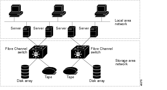
Storage Area Networks
Storage area networks (SANs) represent the latest stage in the evolution of mass data storage for enterprises and other large institutions. In host-centric environments, storage, as well as applications, was centralized and centrally managed. With the advent of client/server environments, information that was previously centralized became distributed across the network. The management problems created by this decentralization are addressed in two principal ways: network attached storage (NAS), where storage devices are directly attached to the LAN, and SANs.
Composed of servers, storage devices (tapes, disk arrays), and network devices (multiplexers, hubs, routers, switches, and so on), a SAN constitutes an entirely separate network from the LAN (see Figure 3-3). As a separate network, the SAN can relieve bottlenecks in the LAN by providing the resources for applications such as data mirroring, transaction processing, and backup and restoration.
Figure 3-3 SAN Architecture
A number of types of interfaces have been used to connect servers to devices in a SAN. The most prevalent is IBM's Enterprise System Connection (ESCON), a 17-MBps half-duplex protocol over fiber.
Fibre Channel, on which IBM's FICON is based, is also frequently employed in SANs and has a much higher capacity than ESCON (see the "Fibre Channel" section.) Both technologies, however, have significant distance limitations. For example, the standard maximum distance without repeaters is around 3 km (1.9 mi) for half duplex ESCON and around 10 km (6.2 mi) for full duplex 100-MBps Fibre Channel. There is performance degradation as distances increase beyond these numbers.
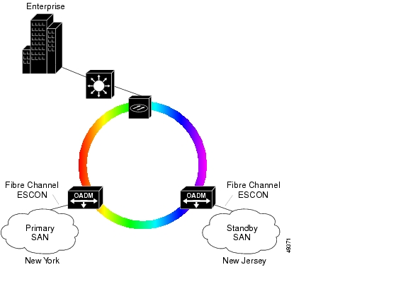
This distance limitation can be overcome by transporting data between one or more enterprise locations and one or more SANs over the optical layer using DWDM. In Figure 3-4, for example, the distance separating the enterprise location and the SAN sites can be greatly extended. Access to the ring is by way of "satellite" OADMs with Fibre Channel or ESCON interfaces at each SAN location (one of these could provide data mirroring). These interfaces can also support Sysplex Timer and Sysplex Coupling Link interfaces, used in IBM environments for distributing loads across the members of a server complex.
Figure 3-4 SAN Access over the Optical Layer
In addition to overcoming distance limitations, DWDM can also reduce fiber requirements in SANs. Both ESCON and FICON require a pair of fibers for every channel. By multiplexing these channels over DWDM transport, significant savings can be realized.
Migration from SONET/SDH
As a transport technology, SONET is an "agnostic" protocol that can transport all traffic types, while providing interoperability, protection schemes, network management, and support for a TDM hierarchy. Although SONET may continue to be the interface standard and transport protocol of choice well into the foreseeable future, upgrading it is expensive, as line-rate specific network elements are required at each point of traffic ingress or egress.
Using DWDM to increase the capacity of embedded fiber, while preserving SONET infrastructure, offers an alternative to expensive SONET upgrades. Migration from SONET to DWDM may in fact be the single most important application in the near term. In general, this migration begins by replacing backbones with DWDM, then moves toward the edges of the network.
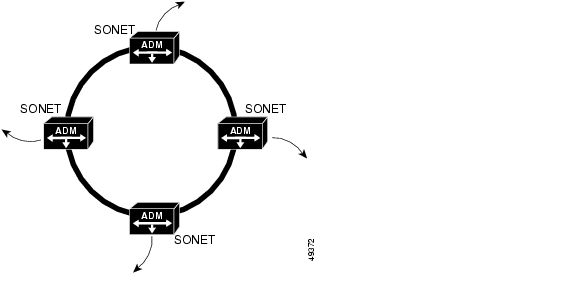
In one common scenario, bandwidth on a SONET ring can be increased greatly by replacing SONET ADMs with DWDM equipment. In the example shown in Figure 3-5, there are three options for upgrading the ring:
•
•
•
Figure 3-5 Migrating the SONET Ring to DWDM—Before
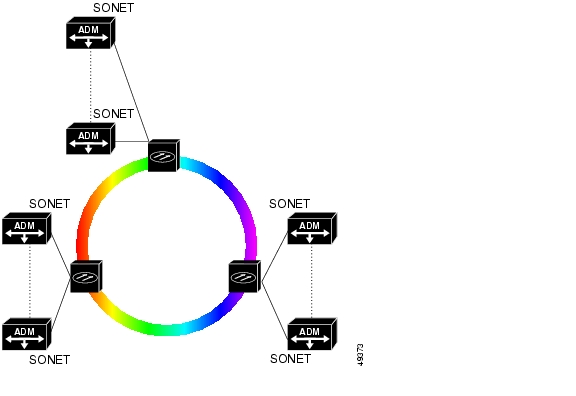
The third option is shown in Figure 3-6. By using DWDM to increase the capacity of the existing ring, one fiber can essentially act as many.
Figure 3-6 Migrating the SONET Ring to DWDM—First Stage
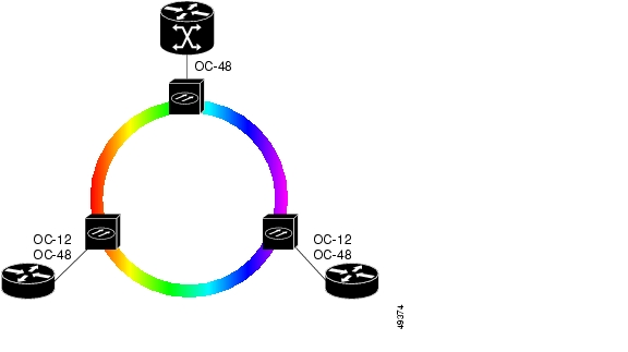
In a second type of scenario, DWDM can be used to remove an entire class of equipment, the SONET ADMs. This change, which might constitute a second phase of SONET migration, allows routers and other devices to bypass SONET equipment and interface directly to DWDM, while simplifying traffic from IP/ATM/SONET to POS to eventually IP directly over the optical layer (see Figure 3-7).
Figure 3-7 Migrating the SONET Ring to DWDM—Second Stage
In this phase of migration, end user sites are served by OADMs rather than SONET ADMs. In this way DWDM rings and mesh networks can eliminate the increased cost and complexity of introducing more SONET elements into the network to meet demand. The advantage here for carriers is the ability to offer bit-rate-independent services, freeing them from the DS1/DS3/OC-n framework. Such a scheme would also allow enterprise LAN access to be extended across the MAN or WAN without a SONET infrastructure.
A further advantage in migrating from SONET to the optical layer is that protection and restoration becomes less susceptible to failure of electronic components; a common survivability platform for all network services is created, including those without built-in protection.
Topologies and Protection Schemes for DWDM
Network architectures are based on many factors, including types of applications and protocols, distances, usage and access patterns, and legacy network topologies. In the metropolitan market, for example, point-to-point topologies might be used for connecting enterprise locations, ring topologies for connecting inter-office facilities (IOFs) and for residential access, and mesh topologies might be used for inter-POP connections and connections to the long-haul backbone. In effect, the optical layer must be capable of supporting many topologies and, because of unpredictable developments in this area, those topologies must be flexible.
Today, the main topologies in deployment are point-to-point and ring. With point-to-point links over DWDM between large enterprise sites, there needs only to be a customer premise device for converting application traffic to specific wavelengths and multiplexing. Carriers with linear-ring topologies can evolve toward full rings based on OADMs. As configurable optical cross-connects and switches become more common, these point-to-point and ring networks will be interconnected into meshes, transforming optical metropolitan networks into fully flexible platforms.
Point-to-Point Topologies
Point-to-point topologies can be implemented with or without OADM. These networks are characterized by ultra-high channel speeds (10 to 40 Gbps), high signal integrity and reliability, and fast path restoration. In long-haul networks, the distance between transmitter and receiver can be several hundred kilometers, and the number of amplifiers required between endpoints is typically less than 10. In the MAN, amplifiers are often not needed.
Protection in point-to-point topologies can be provided in a couple of ways. In first generation equipment, redundancy is at the system level. Parallel links connect redundant systems at either end. Switchover in case of failure is the responsibility of the client equipment (a switch or router, for example), while the DWDM systems themselves just provide capacity.
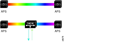
In second generation equipment, redundancy is at the card level. Parallel links connect single systems at either end that contain redundant transponders, multiplexers, and CPUs. Here protection has migrated to the DWDM equipment, with switching decisions under local control. One type of implementation, for example, uses a 1 + 1 protection scheme based on SONET Automatic Protection Switching (APS). See Figure 3-8.
Figure 3-8 Point-to-Point Architecture
Ring Topologies
Rings are the most common architecture found in metropolitan areas and span a few tens of kilometers. The fiber ring might contain as few as four wavelength channels, and typically fewer nodes than channels. Bit rate is in the range of 622 Mbps to 10 Gbps per channel.
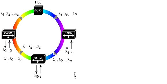
Ring configurations can be deployed with one or more DWDM systems, supporting any-to-any traffic, or they can have a hub station and one or more OADM nodes, or satellites (see Figure 3-9). At the hub node traffic originates, is terminated and managed, and connectivity with other networks is established. At the OADM nodes, selected wavelengths are dropped and added, while the others pass through transparently (express channels). In this way, ring architectures allow nodes on the ring to provide access to network elements such as routers, switches, or servers by adding or dropping wavelength channels in the optical domain. With increase in number of OADMs, however, the signal is subject to loss and amplification can be required.
Figure 3-9 DWDM Hub and Satellite Ring Architecture
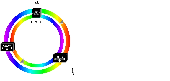
Candidate networks for DWDM application in the metropolitan area are often already based on SONET ring structures with 1 + 1 fiber protection. Thus schemes such as path protection (path protection) or Bidirectional Line Switched Ring (BLSR) can be reused for DWDM implementations. Figure 3-10 shows a path protection scheme with two fibers. Here, hub and nodes send on two counter-rotating rings, but the same fiber is normally being used by all equipment to receive the signal; hence the name unidirectional. If the working ring should fail, the receiving equipment switches to the other pair. Although this provides full redundancy to the path, no bandwidth reuse is possible, as the redundant fiber must always be ready to carry the working traffic. This scheme is most commonly used in access networks.
Figure 3-10 path protection Protection on a DWDM Ring
Other schemes, such as Bidirectional Line Switched Ring (BLSR), allow traffic to travel from the sending to the receiving node by the most direct route. Because of this, BLSR is considered preferable for core SONET networks, especially when implemented with four fibers, which offers complete redundancy.
Mesh Topologies
Mesh architectures are the future of optical networks. As networks evolve, rings and point-to-point architectures will still have a place, but mesh promises to be the most robust topology. This development will be enabled by the introduction of configurable optical cross-connects and switches that will in some cases replace and in other cases supplement fixed DWDM devices.
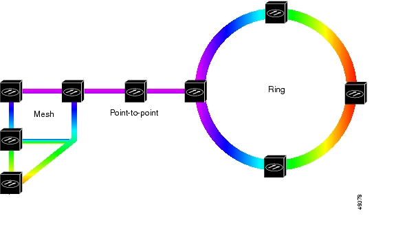
From a design standpoint, there is a graceful evolutionary path available from point-to-point to mesh topologies. By beginning with point-to-point links, equipped with OADM nodes at the outset for flexibility, and subsequently interconnecting them, the network can evolve into a mesh without a complete redesign. Additionally, mesh and ring topologies can be joined by point-to-point links (see Figure 3-11).
Figure 3-11 Mesh, Point-to-Point, and Ring Architectures
DWDM mesh networks, consisting of interconnected all-optical nodes, will require the next generation of protection. Where previous protection schemes relied upon redundancy at the system, card, or fiber level, redundancy will now migrate to the wavelength level. This means, among other things, that a data channel might change wavelengths as it makes its way through the network, due either to routing or to a switch in wavelength because of a fault. The situation is analogous to that of a virtual circuit through an ATM cloud, which can experience changes in its virtual path identifier (VPI)/virtual channel identifier (VCI) values at switching points. In optical networks, this concept is sometimes called a light path.
Mesh networks will therefore require a high degree of intelligence to perform the functions of protection and bandwidth management, including fiber and wavelength switching. The benefits in flexibility and efficiency, however, are potentially great. Fiber usage, which can be low in ring solutions because of the requirement for protection fibers on each ring, can be improved in a mesh design. Protection and restoration can be based on shared paths, thereby requiring fewer fiber pairs for the same amount of traffic and not wasting unused wavelengths.
Finally, mesh networks will be highly dependent upon software for management. A protocol based on Multiprotocol Label Switching (MPLS) is under development to support routed paths through an all-optical network. In addition, network management will require an as-yet unstandardized channel to carry messages among the network elements.
Practical Considerations in Deploying DWDM
In deploying a DWDM-based network there are some considerations that will affect one's choice of vendor, equipment type, design, and so on. Some of these questions are as follows:
•
As discussed in the "Optical Fibers" section, some types of older fiber are not suitable for DWDM use, while newer types, such as NZ-DSF, are optimized for DWDM. Standard SM fiber (G. 652), which currently accounts for the majority of installed fiber, can support DWDM in the metropolitan area. If new fiber must be laid, a type should be chosen that will allow for future growth, particularly as DWDM systems expand into new wavelength regions and higher bit rates.
•
Because DWDM is capable of supporting massive growth in bandwidth demands over time without forklift upgrades, it represents a long-term investment. As discussed in the "Mesh Topologies" section, both point-to-point and ring topologies can serve as foundations for future growth into mesh topologies. Planning should allow for flexible additions of nodes, such as OADMs, to meet the changing demands of customers and usage.
•
A comprehensive network management tool will be needed for provisioning, performance monitoring, fault identification and isolation, and remedial action. Such a tool should be standards-based (SNMP, for example) and be able to interoperate with the existing operating system.
•
Designing a protection strategy is a complex process that must take into account many variables. There are hard failures (equipment failures, such as laser or photodetector, and fiber breaks) and soft failures such as signal degradation (for example, unacceptable BER). The former must be addressed through redundancy at the device, component, or fiber level. The latter must be addressed by the system through intelligent wavelength monitoring and management. Protection and survivability strategies depend upon service type, system, and network architectures. In many networks, they also depend on the transport protocol.
Two additional and important considerations are calculation of the optical power budget and interoperability.
Optical Power Budget
Optical power budgets, or link loss budgets, are a critical part of planning an optical network. Vendors must provide guidelines, or engineering rules, to use for their equipment. In general, there are many factors that can result in optical signal loss. The most obvious of these is the distance of the fiber itself; this tends to be the most important factor in long-haul transport. In MANs, the number of access nodes, such as OADMs, is generally the most significant contributor to optical loss.
The key to precise optical power budget calculation is to get an accurate reading on the fiber using an optical time domain reflectometer (OTDR). Using an OTDR, you can obtain the following information about a span:
•
•
•
•
The goal in calculating optical loss is to ensure that the total loss does not exceed the span budget. The following are typical values for the main elements in a span:
•
•
•
Because optical power loss (or gain) is measured in a logarithmic value, decibels (dBs), the combined effect of all contributing elements can be calculated using simple addition. Assume a span budget of 25 dBm (a dBm is the signal power level in relation to one milliwatt), we can make the following addition:
total system loss + (fiber length *.25) + fiber aging margin + connector/splice losses
If the sum is less than 25, then we are within the span budget. If not, then some changes must be made. This might include adding an amplifier or reducing the number of loss-inducing elements on the span. Fiber conditioning, which includes resplicing fiber, connector cleaning, and so on, may also be required to reduce loss.
It is also important to ensure that the client side or tributary equipment does not overdrive the local receive laser of the DWDM equipment. This means that the client or tributary equipment must operate within the specifications of the DWDM client interface.
Although it is generally not an issue at the distances used in the MAN, remember that optical amplifiers boost the entire input, including noise. Thus over time the signal-to-noise ratio becomes so high that a clear signal can no longer be detected at the receiving end. At this point regenerators must be used to perform the 3R functions.
Interoperability Issues
Because DWDM uses specific wavelengths for transmission, the wavelengths used must be the same on either end of any given connection. Toward this end, the ITU has standardized on a grid with spacings of 100 GHz (see Table 2-1). However, vendors may use wider spacing, sometimes at 200 GHz, or narrower. In addition, different vendors who do use the same grid may not use the same lambda numbering scheme. That is, lambda 1 on vendor A's equipment may be assigned a different wavelength from lambda 1 on vendor B's equipment. Hence, it is important to be aware of the potential interoperability problems posed by different grid alignments.
Other interoperability issues include power levels, inter- and intra-channel isolation, PMD tolerances, and fiber types. All these contribute to the challenges of transmission between different systems at
Layer 1.Future of DWDM
DWDM will continue to provide the bandwidth for large amounts of data. In fact, the capacity of systems will grow as technologies advance that allow closer spacing, and therefore higher numbers, of wavelengths. But DWDM is also moving beyond transport to become the basis of all-optical networking with wavelength provisioning and mesh-based protection. Switching at the photonic layer will enable this evolution, as will the routing protocols that allow light paths to traverse the network in much the same way as virtual circuits do today.
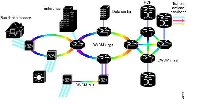
These and other advances are converging such that an all-optical infrastructure can be envisioned. Figure 3-12 shows an example of such an infrastructure, using mesh, ring, and point-to-point topologies at the optical layer to support the needs of enterprise, metropolitan access, and metropolitan core networks.
Figure 3-12 Next Generation Metropolitan Optical Network
![]()
![]()
![]()
![]()
![]()
![]()
![]()
![]()
Posted: Thu Apr 13 23:32:31 PDT 2006
All contents are Copyright © 1992--2006 Cisco Systems, Inc. All rights reserved.
Important Notices and Privacy Statement.