|
|

Table Of Contents
NTP-9 Configure Management Access
DLP-41 Configure the Enable Password
DLP-42 Configure the Enable Secret Password
DLP-43 Configure IP Access on the NME Interfaces
DLP-45 Configure System Time, Time Zone, and System Log Time Stamps
DLP-46 Configure IP on the OSC Using the Loopback Interface
DLP-47 Configure IP on the OSC Using the NME Fastethernet 0 Interface
DLP-48 Configure 2.5-Gbps Transponder Module Interfaces
DLP-49 Configure 10-GE Transponder Module Interfaces
DLP-50 Configure PSM Interfaces
NTP-11 Configure Patch Connections
DLP-51 Configure Splitter Protection
DLP-52 Configure Y-Cable Line Card Protection
DLP-53 Configure Trunk Fiber Based Protection
DLP-54 Configure Path Switching
NTP-14 Verify the System Configuration
Software Setup Procedures
This chapter describes procedures for basic software configuration.
Note
The procedures and tasks in this chapter assume that you are familiar with the Cisco IOS CLI (command-line interface) and that you have access to the Cisco ONS 15540 ESPx technical documentation. The technical documentation is available at the following URL:
http://www.cisco.com/en/US/products/hw/optical/ps2011/ps4002/index.html
Before You Begin
This section lists the chapter non-trouble procedure (NTPs). Turn to a procedure for applicable tasks or detailed level procedures (DLPs).
Step 1
Step 2
Step 3
Step 4
Step 5
Step 6
Use the data checklist forms to record such information as IP address and host name for each node. Refer to this information when performing the procedures in this section.
Refer to the Cisco ONS 15540 ESPx Configuration Guide and the Cisco ONS 15540 ESPx Command Reference for more detailed configuration information.
NTP-9 Configure Management Access
Step 1
Step 2
Step 3
Step 4
Step 5
Step 6
Step 7
DLP-41 Configure the Enable Password
The enable password is a nonencrypted password. It can contain any number of uppercase and lowercase alphanumeric characters. Give the enable password only to users permitted to make configuration changes.
DLP-42 Configure the Enable Secret Password
DLP-43 Configure IP Access on the NME Interfaces
Purpose
This task configures IP access on the NME (network management Ethernet) interfaces on the active processor cards. This allows multiple, simultaneous remote Telnet or SNMP network management sessions.
Tools/Equipment
None
Prerequisite Procedures
41 Configure the Enable Password
Obtain an IP address and IP subnet mask for the NME interface on the active processor card and a separate IP address and IP subnet mask for the NME interface on the standby processor card, if any.
Required/As Needed
Required
Onsite/Remote
Onsite or remote
Security Level
Privileged
Example
The following example shows how to configure IP access on the NME interface fastethernet 0:
Switch# configure terminalSwitch(config)# interface fastethernet 0Switch(config-if)# ip address 192.31.7.18 255.255.255.0Switch(config-if)# exitSwitch(config)# ip default-gateway 192.31.7.1Switch(config)# endSwitch# copy system:running-config nvram:startup-configDLP-44 Configure Host Name
Purpose
This task configures the system host name, which allows you to keep track of the nodes in your network.
Tools/Equipment
None
Prerequisite Procedures
41 Configure the Enable Password
Obtain a host name for the system.
Required/As Needed
Required
Onsite/Remote
Onsite or remote
Security Level
Privileged
Example
The following example shows how to configure the host name:
Switch# configure terminalSwitch(config)# hostname node1node1(config)# endnode1# copy system:running-config nvram:startup-configDLP-45 Configure System Time, Time Zone, and System Log Time Stamps
Purpose
This task configures the system time and time zone for the system, and enables time stamps for the system log entries.
Tools/Equipment
None
Prerequisite Procedures
41 Configure the Enable Password
Obtain a host name for the system.
Required/As Needed
Required
Onsite/Remote
Onsite or remote
Security Level
Privileged
Example
The following example shows how to configure the host name:
Switch# clock set 10:30:00 1 nov 2003Switch# configure terminalSwitch(config)# timezone pst -8Switch(config)# clock summer-time pdt recurring last sun apr 2:00 last sun oct 2:00 60Switch(config)# service timestamps log datetime msec localtime show-timezoneSwitch(config)# endSwitch# copy system:running-config nvram:startup-configDLP-46 Configure IP on the OSC Using the Loopback Interface
Purpose
This task configures IP access on the OSC for network management using the loopback interface as a reference. The loopback interface is a software-only virtual interface that is always up and allows routing protocol sessions to stay up even if the OSC wave interface is down.
Tools/Equipment
None
Prerequisite Procedures
43 Configure IP Access on the NME Interfaces
DLP-8 Install the Mux/Demux Motherboard, page 2-15, with OSC
Obtain an IP address for loopback interface with a subnet separate from the NME fastethernet 0 interface.
Required/As Needed
As needed
Onsite/Remote
Onsite or remote
Security Level
Privileged
Example
The following example shows how to configure IP on an OSC wave interface:
Switch# configure terminalSwitch(config)# interface loopback 1Switch(config-if)# ip address 192.31.7.18 255.255.255.0Switch(config-if)# exitSwitch(config)# interface wave 0Switch(config-if)# ip unnumbered loopback 1Switch(config-if)# no shutdownSwitch(config-if)# exitSwitch(config)# interface wave 1Switch(config-if)# ip unnumbered loopback 1Switch(config-if)# no shutdownSwitch(config-if)# exitSwitch(config)# router ospf 109Switch(config-router)# network 192.31.20.0 0.0.0.255 area 10.9.50.0Switch(config-router)# network 192.31.0.0 0.0.255.255 area 2Switch(config-router)# network 192.31.10.0 0.0.0.255 area 3Switch(config-router)# network 0.0.0.0 255.255.255.255 area 0Switch(config-router)# endSwitch# copy system:running-config nvram:startup-config
Note
Cisco IOS IP and IP Routing Configuration Guide.DLP-47 Configure IP on the OSC Using the NME Fastethernet 0 Interface
Purpose
This task configures IP access on the OSC for network management using the NME fastethernet 0 interface as a reference.
Tools/Equipment
None
Prerequisite Procedures
43 Configure IP Access on the NME Interfaces
DLP-8 Install the Mux/Demux Motherboard, page 2-15, with OSC
Required/As Needed
As needed
Onsite/Remote
Onsite or remote
Security Level
Privileged
Example
The following example shows how to configure IP on an OSC wave interface:
Switch# configure terminalSwitch(config)# interface wave 0Switch(config-if)# ip unnumbered fastethernet 0Switch(config-if)# no shutdownSwitch(config-if)# exitSwitch(config)# interface wave 1Switch(config-if)# ip unnumbered fastethernet 0Switch(config-if)# no shutdownSwitch(config-if)# exitSwitch(config)# router ospf 109Switch(config-router)# network 131.108.20.0 0.0.0.255 area 10.9.50.0Switch(config-router)# network 131.108.0.0 0.0.255.255 area 2Switch(config-router)# network 131.109.10.0 0.0.0.255 area 3Switch(config-router)# network 0.0.0.0 255.255.255.255 area 0Switch(config-router)# network 0.0.0.0 255.255.255.255 area 0Switch(config-router)# endSwitch# copy system:running-config nvram:startup-config
Note
Cisco IOS IP and IP Routing Configuration Guide.NTP-10 Configure Interfaces
Step 1
Step 2
Step 3
DLP-48 Configure 2.5-Gbps Transponder Module Interfaces
Step 1
Switch> enable
Password:Switch#
Enters privileged EXEC mode.
Step 2
Switch#
configure terminalSwitch(config)#
Enters global configuration mode.
Step 3
Switch(config)# interface transparent slot/subcard/0
Switch(config-if)#
Selects the interface to configure and enters interface configuration mode.
Step 4
Switch(config-if)# encapsulation {fastethernet | fddi | gigabitethernet | escon}
orSwitch(config-if)# encapsulation sysplex clo
orSwitch(config-if)# encapsulation sysplex etr
orSwitch(config-if)# encapsulation sysplex isc {compatibility | peer [1g | 2g]}
orSwitch(config-if)# encapsulation ficon {1g | 2g}
orSwitch(config-if)# encapsulation sonet {oc3 | oc12 | oc48}
orSwitch(config-if)# encapsulation sdh {stm-1 | stm-4 | stm-16}
orSwitch(config-if)# encapsulation fibrechannel {1g | 2g} [ofc {enable | disable}]
orSwitch(config-if)# clock rate value
Specifies Fast Ethernet, FDDI, Gigabit Ethernet, or ESCON. OFC is disabled.
Specifies Sysplex CLO1 . OFC2 is disabled. Forward laser control is enabled on both the transparent and wave interfaces. OFC is disabled.
Specifies Sysplex ETR3 . OFC is disabled.
Specifies ISC4 compatibility mode (1 Gbps) or peer mode (1 Gbps or 2 Gbps). OFC is enabled for compatibility mode and disabled for peer mode.
Specifies FICON encapsulation and rate. OFC is disabled.
Specifies SONET as the signal protocol and OC-3, OC-12, or OC-48 as the transmission rate. OFC is disabled.
Specifies SDH as the signal protocol and STM-1, STM-4, or STM-16 as the transmission rate. OFC is disabled.
Specifies Fibre Channel as the signal protocol and 1 Gbps or 2 Gbps as the transmission rate. Enables or disables OFC. OFC is disabled by default.
Specifies the signal transmission clock rate without an associated protocol. OFC is disabled.
Step 5
Switch(config-if)# monitor enable
Enables protocol monitoring. Protocol monitoring is supported only for certain protocol encapsulations.
Step 6
Switch(config-if)# topology neighbor {name node-name | ip-address node-ip-address | mac-address node-mac-address} {port {name port-name | ip-address port-ip-address | mac-address port-mac-address}}
[receive | transmit]Configures the network topology information for the client equipment.
Step 7
Switch(config-if)# topology neighbor agent ip-address ip-address
Specifies the address of the network topology agent on a neighboring node.
Step 8
Switch(config-if)# no shutdown
Enables the interface.
Step 9
Switch(config-if)# exit
Switch(config)#
Exits interface configuration mode and returns to global configuration mode.
Step 10
Switch(config)# interface wave slot/subcard
Switch(config-if)#
Selects the interface to configure and enters interface configuration mode.
Step 11
Switch(config-if)# laser frequency number
Selects the frequency for the trunk transmit laser. The default is the lower channel frequency for the 2.5-Gbps transponder module in even numbered subslots and the higher channel frequency for the 2.5-Gbps transponder module in the odd numbered subslots.
Step 12
Switch(config-if)# no shutdown
Enables the interface.
Step 13
Switch(config-if)# exit
Switch(config)#
Exits interface configuration mode and returns to global configuration mode.
Step 14
Switch(config)# interface wavepatch slot/subcard/0
Switch(config-if)#
Selects the interface to configure and enters global configuration mode.
Note
Step 15
Switch(config-if)# no shutdown
Enables the interface.
Step 16
Switch(config-if)# exit
Switch(config)#
Exits interface configuration mode and returns to global configuration mode.
Step 17
Switch(config)# interface wavepatch slot/subcard/1
Switch(config-if)#
Selects the interface to configure and enters global configuration mode.
Note
Step 18
Switch(config-if)# no shutdown
Enables the interface.
Step 19
Switch(config-if)# end
Switch#
Returns to privileged EXEC mode.
Step 20
Switch#
copy system:running-config nvram:startup-configSaves your configuration changes to NVRAM.
1 CLO = control link oscillator
2 OFC = open fiber control
3 ETR = external timer reference
4 ISC = InterSystem Channel links
Example
The following example shows how to configure the 2.5-Gbps transponder module interfaces:
Switch# configure terminalSwitch(config)# interface transparent 2/0/0Switch(config-if)# encapsulation sonet oc48Switch(config-if)# monitor enableSwitch(config-if)# topology neighbor ip-address 192.31.7.11 port ip-address 192.31.7.13Switch(config-if)# topology neighbor agent ip-address 192.31.7.20Switch(config-if)# no shutdownSwitch(config-if)# exitSwitch(config)# interface wave 2/0Switch(config-if)# no shutdownSwitch(config-if)# exitSwitch(config)# interface wavepatch 2/0/0Switch(config-if)# no shutdownSwitch(config-if)# exitSwitch(config)# interface wavepatch 2/0/1Switch(config-if)# no shutdownSwitch(config-if)# endSwitch# copy system:running-config nvram:startup-configDLP-49 Configure 10-GE Transponder Module Interfaces
Step 1
Switch> enable
Password:Switch#
Enters privileged EXEC mode.
Step 2
Switch#
configure terminalSwitch(config)#
Enters global configuration mode.
Step 3
Switch(config)# interface tengigethernetphy slot/subcard
Switch(config-if)#
Selects the interface to configure and enters interface configuration mode.
Step 4
Switch(config-if)# no shutdown
Enables the interface.
Step 5
Switch(config-if)# no laser shutdown
Turns on the client-side laser.
Step 6
Switch(config-if)# topology neighbor {name node-name | ip-address node-ip-address | mac-address node-mac-address} {port {name port-name | ip-address port-ip-address | mac-address port-mac-address}}
[receive | transmit]Configures the network topology information for the client equipment.
Step 7
Switch(config-if)# topology neighbor agent ip-address ip-address
Specifies the address of the network topology agent on the client equipment.
Step 8
Switch(config-if)# exit
Switch(config)#
Exits interface configuration mode and returns to global configuration mode.
Step 9
Switch(config)# interface waveethernetphy slot/subcard
Switch(config-if)#
Selects the interface to configure and enters interface configuration mode.
Step 10
Switch(config-if)# no shutdown
Enables the interface.
Step 11
Switch(config-if)# no laser shutdown
Turns on the ITU laser.
Note
Step 12
Switch(config-if)# exit
Switch(config)
Returns to global configuration mode.
Step 13
Switch(config)# interface wavepatch slot/0/0
Switch(config-if)#
Selects the interface to configure and enters interface configuration mode.
Step 14
Switch(config-if)# [no] shutdown
Enables or disables the interface.
Repeat Step 13 and Step 14 on wavepatch slot/0/1 for splitter 10-GE transponder modules.
Step 15
Switch(config-if)# end
Switch#
Returns to privileged EXEC mode.
Step 16
Switch#
copy system:running-config nvram:startup-configSaves your configuration changes to NVRAM.
Example
The following example shows how to configure the 10-GE transponder module interfaces:
Switch# configure terminalSwitch(config)# interface tengigethernetphy 9/0Switch(config-if)# no shutdownSwitch(config-if)# no laser shutdownSwitch(config-if)# exitSwitch(config)# interface waveethernetphy 9/0Switch(config-if)# no shutdownSwitch(config-if)# no laser shutdownSwitch(config-if)# exitSwitch(config)# interface wavepatch 9/0/0Switch(config-if)# no shutdownSwitch(config-if)# exitSwitch(config)# interface wavepatch 9/0/1Switch(config-if)# no shutdownSwitch(config-if)# endSwitch# copy system:running-config nvram:startup-configDLP-50 Configure PSM Interfaces
Purpose
This task configures the PSM interfaces.
Tools/Equipment
None
Prerequisite Procedures
Required/As Needed
As needed
Onsite/Remote
Onsite or remote
Security Level
Privileged
Example
The following example shows how to enable wdmsplit interfaces:
Switch(config)# interface wdmsplit 0/0/0Switch(config-if)# no shutdownSwitch(config-if)# exitSwitch(config)# interface wdmsplit 0/0/1Switch(config-if)# no shutdownSwitch(config-if)# endSwitch# copy system:running-config nvram:startup-configNTP-11 Configure Patch Connections
Purpose
This procedure configures the patch connections on the CLI.
Tools/Equipment
None
Prerequisite Procedures
Required/As Needed
Required
Onsite/Remote
Onsite or remote
Security Level
Privileged
Step 1
Step 2
Step 3
Step 4
Table 3-1 describes the types of patch connections on the Cisco ONS 15540 ESPx.
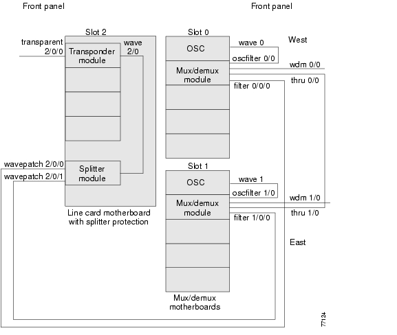
Figure 3-1 and Figure 3-2 show examples of 2.5-Gbps transponder module interfaces and their optical patch connections to mux/demux modules.
Figure 3-1 Optical Patch Connection Example for Splitter Protection With 2.5-Gbps Transponder Modules
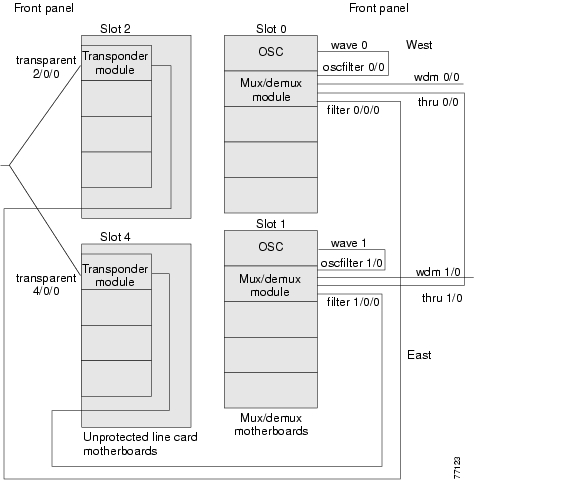
Figure 3-2 Optical Patch Connection Example for Y-Cable Protection With 2.5-Gbps Transponder Modules
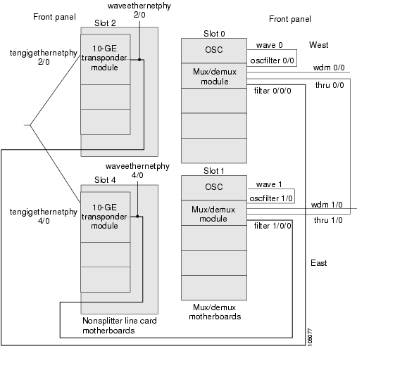
Figure 3-3 and Figure 3-4 show examples of 10-GE transponder module interfaces and their optical patch connections to mux/demux modules.
Figure 3-3 Optical Patch Connection Example for Splitter Protection With 10-GE Transponder Modules
Figure 3-4 Optical Patch Connection Example for Y-Cable Protection With 10-GE Transponder Modules
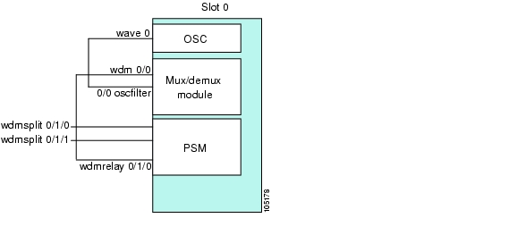
Figure 3-5 shows an example of PSM interfaces and their optical patch connections to a 4-channel or 8-channel mux/demux module.
Figure 3-5 Optical Patch Connection Example Between a PSM and a 4-Channel or 8-Channel Mux/Demux Module
Note
Example
The following example shows how to configure the patch connections between modules:
Switch# configure terminalSwitch(config)# patch thru 0/0 thru 1/0Switch(config)# patch wavepatch 3/0/0 filter 0/0/1Switch(config)# patch wavepatch 3/1/0 filter 1/0/1Switch(config)# patch wave 0 oscfilter 0/0Switch(config)# patch wave 1 oscfilter 1/0Switch(config)# endSwitch# copy system:running-config nvram:startup-configNTP-12 Configure APS
Purpose
This procedure describes how to configure APS groups for protection.
Tools/Equipment
None
Prerequisite Procedures
48 Configure 2.5-Gbps Transponder Module Interfaces
Required/As Needed
As needed
Onsite/Remote
Onsite or remote
Security Level
Privileged
Step 1
Step 2
Step 3
Step 4
For more information on APS, refer to the Cisco ONS 15540 ESPx Configuration Guide and the Cisco ONS 15540 ESPx Command Reference.
DLP-51 Configure Splitter Protection
Purpose
This task configures splitter protection, which provides facility protection.
Tools/Equipment
None
Prerequisite Procedures
DLP-9 Install the 4-Channel Mux/Demux Module, page 2-17, or
DLP-10 Install the 8-Channel Mux/Demux Module, page 2-17, or
DLP-11 Install the 32-Channel Terminal Mux/Demux Module, page 2-17, for two mux/demux modulesDLP-15 Install the Type 1 SM Transponder Module, page 2-21, or
DLP-16 Install the Type 1 MM Transponder Module, page 2-22, or
DLP-17 Install the 10-GE Transponder Module, page 2-23, or
DLP-18 Install the Type 2 Extended Range Transponder Module, page 2-24, in a splitter line card motherboard for the APS groupRequired/As Needed
As needed
Onsite/Remote
Onsite or remote
Security Level
Privileged
Examples
This example shows how to associate wavepatch interfaces for splitter protection.
Switch#configure terminalSwitch(config)# redundancySwitch(config-red)# associate group dallas1Switch(config-red-aps)# aps working wavepatch 3/0/0Switch(config-red-aps)# aps protection wavepatch 3/0/1Switch(config-red-aps)# aps enableSwitch(config-red-aps)# endSwitch# copy system:running-config nvram:startup-configDLP-52 Configure Y-Cable Line Card Protection
Purpose
This task configures y-cable protection, which provides facility and line card protection.
Tools/Equipment
None
Prerequisite Procedures
DLP-9 Install the 4-Channel Mux/Demux Module, page 2-17, or
DLP-10 Install the 8-Channel Mux/Demux Module, page 2-17, or
DLP-11 Install the 32-Channel Terminal Mux/Demux Module, page 2-17, for two mux/demux modulesDLP-15 Install the Type 1 SM Transponder Module, page 2-21, or
DLP-16 Install the Type 1 MM Transponder Module, page 2-22, or
DLP-17 Install the 10-GE Transponder Module, page 2-23, or
DLP-18 Install the Type 2 Extended Range Transponder Module, page 2-24, for two transponder modules, each in a separate nonsplitter line card motherboard, for the APS groupRequired/As Needed
As needed
Onsite/Remote
Onsite or remote
Security Level
Privileged
Caution
Example
This example shows how to associate two transparent interfaces for y-cable line card protection.
Switch# configure terminalSwitch(config)# redundancySwitch(config-red)# associate group YosemiteSwitch(config-red-aps)# aps working transparent 3/0/0Switch(config-red-aps)# aps protection transparent 4/0/0Switch(config-red-aps)# aps y-cableSwitch(config-red-aps)# aps enableSwitch(config-red-aps)# endSwitch# copy system:running-config nvram:startup-configDLP-53 Configure Trunk Fiber Based Protection
Purpose
This task configures y-cable protection, which provides facility and line card protection.
Tools/Equipment
None
Prerequisite Procedures
DLP-28 Connect the PSM to a Remote PSM, page 2-36
Required/As Needed
As needed
Onsite/Remote
Onsite or remote
Security Level
Privileged
Examples
The following example shows how to configure trunk fiber protection:
Switch(config)# redundancySwitch(config-red)# associate group psm-groupSwitch(config-red-aps)# aps working wdmsplit 0/1/0Switch(config-red-aps)# aps protection wdmsplit 0/1/1Switch(config-red-aps)# aps message-channel ip far-end group-name psm-group ip-address 172.18.44.93Switch(config-red-aps)# aps enableSwitch(config-red-aps)# endSwitch# copy system:running-config nvram:startup-configDLP-54 Configure Path Switching
Purpose
This task configures path switching behavior for an APS group.
Tools/Equipment
None
Prerequisite Procedures
51 Configure Splitter Protection or
52 Configure Y-Cable Line Card Protection
53 Configure Trunk Fiber Based ProtectionRequired/As Needed
As needed
Onsite/Remote
Onsite or remote
Security Level
Privileged
Note
Example
This example shows how to configure bidirectional path switching.
Switch# configure terminalSwitch(config)# redundancySwitch(config-red)# associate group YosemiteSwitch(config-red-aps)# aps disableSwitch(config-red-aps)# aps direction bidirectionalSwitch(config-red-aps)# aps enableSwitch(config-red-aps)# endSwitch# copy system:running-config nvram:startup-configNTP-13 Configure SNMP
Purpose
This procedure configures SNMP trap messages for the system.
Tools/Equipment
None
Prerequisite Procedures
Required/As Needed
As needed
Onsite/Remote
Onsite or remote
Security Level
Privileged
Example
The following example shows how to configure and test SNMP functionality:
Switch# configure terminalSwitch(config)# snmp-server community public ROSwitch(config)# snmp-server community private RWSwitch(config)# snmp-server host 172.30.2.160 public snmp alarmsSwitch(config)# snmp-server enable trapsSwitch(config)# interface transparent 8/0/0Switch(config-if)# shutdownSwitch(config-if)# no shutdownSwitch(config-if)# endSwitch# copy system:running-config nvram:startup-configNTP-14 Verify the System Configuration
Purpose
This procedure describes how to verify the software configuration for the system.
Tools/Equipment
None
Prerequisite Procedures
11 Configure Patch Connections
12 Configure APS, if APS is desired
13 Configure SNMP, if SNMP traps are desired
Required/As Needed
As needed
Onsite/Remote
Onsite or remote
Security Level
Privileged
Step 1
Step 2
Step 3
Step 4
Switch# show configUsing 4489 out of 522232 bytes!version 12.2no service padservice timestamps debug datetime msec localtimeservice timestamps log datetime msec localtimeno service password-encryptionservice internal!hostname Switch!boot system flash bootflash:ons15540-i-mz.122-18.SVboot bootldr bootflash:ons15540-i-mzlogging snmp-authfailenable secret 5 $1$jCgk$nksh2kGZligtPKMnhNsZ9.enable password lab!no environment-monitor shutdown fandiag onlineip subnet-zerono ip routingno ip domain-lookup!!redundancystandby privilege-mode enable!!interface FastEthernet0ip address 172.25.22.60 255.255.255.254no ip route-cacheduplex autospeed autono cdp enable!interface Fastethernet-sby0ip address 172.25.22.61 255.255.255.254no ip route-cacheduplex autospeed auto!interface Filter0/3/0no ip addressno ip route-cache!interface Filter0/2/0no ip address!interface Filter0/0/0no ip addressno ip route-cache!interface Oscfilter0/3no ip addressno ip route-cache!interface Oscfilter0/2no ip address!interface Oscfilter0/0no ip addressno ip route-cache!interface Thru0/3no ip addressno ip route-cache!interface Thru0/2no ip address!interface Thru0/0no ip addressno ip route-cache!interface Wave0no ip addressno ip route-cacheshutdown!interface Wdm0/3no ip addressno ip route-cache!interface Wdm0/2no ip address!interface Wdm0/0no ip addressno ip route-cache!interface WdmRelay0/1/0no ip address!interface WdmSplit0/1/0no ip addressshutdown!interface Filter0/3/1no ip addressno ip route-cache!interface Filter0/2/1no ip address!interface Filter0/0/1no ip addressno ip route-cache!interface WdmSplit0/1/1no ip addressshutdown!interface Filter0/3/2no ip addressno ip route-cache!interface Filter0/2/2no ip address!interface Filter0/0/2no ip addressno ip route-cache!interface Filter0/3/3no ip addressno ip route-cache!interface Filter0/2/3no ip address!interface Filter0/0/3no ip addressno ip route-cache!interface Filter0/2/4no ip address!interface Filter0/2/5no ip address!interface Filter0/2/6no ip address!interface Filter0/2/7no ip address!interface Filter1/0/0no ip addressno ip route-cache!interface Filter1/3/0no ip addressno ip route-cache!interface Oscfilter1/0no ip addressno ip route-cache!interface Thru1/0no ip addressno ip route-cache!interface Thru1/3no ip addressno ip route-cache!interface Wave1no ip addressno ip route-cacheshutdown!interface Wdm1/0no ip addressno ip route-cache!interface Wdm1/3no ip addressno ip route-cache!interface WdmRelay1/1/0no ip address!interface WdmSplit1/1/0no ip addressshutdown!interface Filter1/0/1no ip addressno ip route-cache!interface Filter1/3/1no ip addressno ip route-cache!interface WdmSplit1/1/1no ip addressshutdown!interface Filter1/0/2no ip addressno ip route-cache!interface Filter1/3/2no ip addressno ip route-cache!interface Filter1/0/3no ip addressno ip route-cache!interface Filter1/3/3no ip addressno ip route-cache!interface Filter1/3/4no ip addressno ip route-cache!interface Filter1/3/5no ip addressno ip route-cache!interface Filter1/3/6no ip addressno ip route-cache!interface Filter1/3/7no ip addressno ip route-cache!interface EthernetDcc3/0/0no ip address!interface EthernetDcc3/1/0no ip addressno ip route-cacheshutdown!interface TenGigEthernetPhy3/0no ip address!interface TenGigEthernetPhy3/1no ip addressno ip route-cache!interface WaveEthernetPhy3/0no ip address!interface WaveEthernetPhy3/1no ip addressno ip route-cache!interface Wavepatch3/0/0no ip addressshutdown!interface Wavepatch3/1/0no ip addressno ip route-cache!interface Wavepatch3/0/1no ip address!interface Wavepatch3/1/1no ip addressno ip route-cache!interface Transparent9/3/0no ip addressencapsulation fibreChannel 2Gmonitor enablelaser control forward enable!interface Wave9/3no ip addresslaser control forward enable!interface Wavepatch9/3/0no ip address!interface Wavepatch9/3/1no ip address!ip classlessno ip http server!!snmp-server engineID local 8000000903000008A35D7A31snmp-server community public RWsnmp-server enable traps ttysnmp-server enable traps rf!control-plane!!line con 0exec-timeout 0 0line aux 0line vty 0 4exec-timeout 0 0password labloginlength 0!!endStep 5
![]()
![]()
![]()
![]()
![]()
![]()
![]()
![]()
Posted: Wed Jan 12 14:21:04 PST 2005
All contents are Copyright © 1992--2005 Cisco Systems, Inc. All rights reserved.
Important Notices and Privacy Statement.