|
|

Table Of Contents
Example Shelf Configurations and Topologies
Splitter Protected Configurations
Line Card Protected Configurations
Trunk Fiber Protected Configurations
Unprotected 16 Channel Point-to-Point Configuration with
10-Gbps Line Card MotherboardsProtected 8-Channel Point-to-Point Configuration with
10-Gbps Line Card MotherboardsUnprotected 32-Channel Point-to-Point Configuration
Splitter Protected 32-Channel Point-to-Point Configuration
Line Card Protected 16-Channel Point-to-Point Configuration
Line Card Protected 32-Channel Point-to-Point Configuration
Splitter Protected Hubbed Ring Configuration
Line Card Protected Hubbed Ring Configuration
Splitter Protected Meshed Ring Configuration
Line Card Protected Meshed Ring Configuration
Meshed Ring Topologies with Unprotected Channels
Splitter Protected Meshed Ring with Unprotected Channels Configuration
Line Card Protected Meshed Ring with Unprotected Channels Configuration
Example Shelf Configurations and Topologies
The requirements of a particular topology determine what components must be used and how they are interconnected. This chapter provides examples of shelf configurations, optical power budget calculations, and optical mux/demux module cabling specific to each of the main types of topologies supported by the Cisco ONS 15540 ESPx. This chapter contains the following major sections:
•
Meshed Ring Topologies with Unprotected Channels
Note
Shelf Configurations
The Cisco ONS 15540 ESPx provides two ways to cable transponder motherboards to the mux/demux modules: directly or using the cross connect drawer. This section shows how to cable a single shelf for the different types of protection configuration.
Note
Unprotected Configurations
This section describes the configuration of and cabling between the mux/demux modules and line card motherboard for unprotected configurations.
Note
Direct Cabling
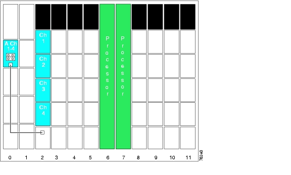
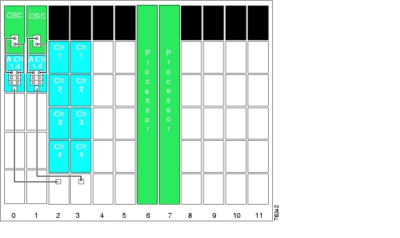
Figure 5-1 shows an example of how to directly cable an unprotected configuration.
Figure 5-1 Direct Cabling Between Line Card Motherboards and 4-Channel Mux/Demux Modules for Unprotected Configurations
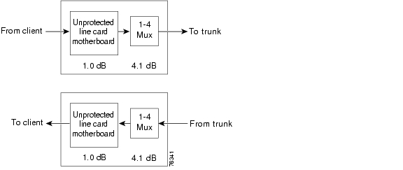
Figure 5-2 shows the optical power budget for a directly connected unprotected configuration.
Figure 5-2 Optical Power Budget for Directly Cabled Unprotected Configurations
Cross Connect Drawer Cabling
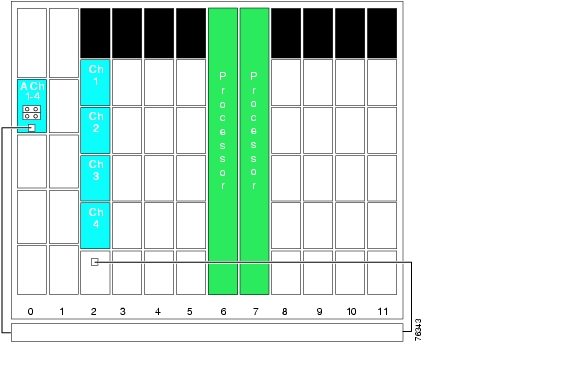
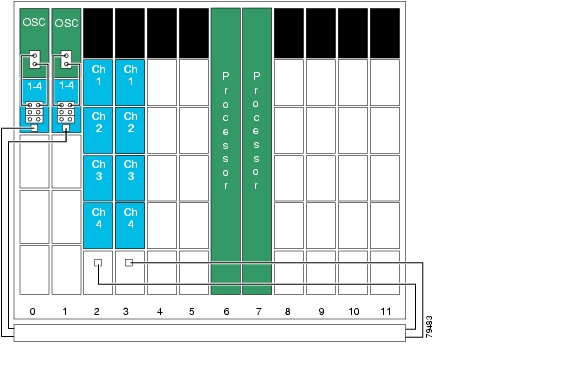
Figure 5-3 shows an example of how to cable an unprotected configuration with the cross connect drawer.
Figure 5-3 Cabling With the Cross Connect Drawer Between Line Card Motherboards and 4-Channel Mux/Demux Modules for Unprotected Configurations
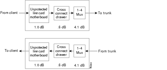
Figure 5-4 shows the optical power budget for a cross connect drawer connected in an unprotected configuration.
Figure 5-4 Optical Power Budget for Cross Connect Drawer Cabled Unprotected Configurations
Splitter Protected Configurations
This section describes the configuration of and cabling between the mux/demux modules and line card motherboards for splitter protected configurations.
Direct Cabling
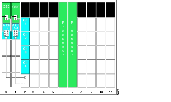
Figure 5-5 shows an example of how to directly cable a splitter protected configuration.
Figure 5-5 Direct Cabling Between Line Card Motherboards and 4-Channel Mux/Demux Modules for Splitter Protected Configurations
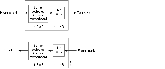
Figure 5-6 shows the optical power budget for a directly connected splitter protected configuration.
Figure 5-6 Optical Power Budget for Directly Cabled Splitter Protected Configurations
Cross Connect Drawer Cabling
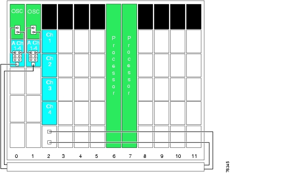
Figure 5-7 shows an example of how to cable a splitter protected configuration with the cross connect drawer.
Figure 5-7 Cabling With the Cross Connect Drawer Between Line Card Motherboards and 4-Channel Mux/Demux Modules for Splitter Protected Configurations
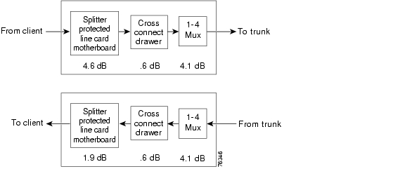
Figure 5-8 shows the optical power budget for a cross connect drawer connected in a splitter protected configuration.
Figure 5-8 Optical Power Budget for Cross Connect Drawer Cabled Splitter Protected Configurations
Line Card Protected Configurations
This section describes the configuration of and cabling between the mux/demux modules and line card motherboards for line card protected configurations.
Direct Cabling
Figure 5-9 shows an example of how to directly cable a line card protected configuration.
Figure 5-9 Direct Cabling Between Line Card Motherboards and 4-Channel Mux/Demux Modules for Line Card Protected Configurations
Figure 5-10 shows the optical power budget for a directly connected line card protected configuration.
Figure 5-10 Optical Power Budget for Directly Cabled Line Card Protected Configurations
Cross Connect Drawer Cabling
Figure 5-11 shows an example of how to cable a line card protected configuration with the cross connect drawer.
Figure 5-11 Cabling With the Cross Connect Drawer Between Line Card Motherboards and 4-Channel Mux/Demux Modules for Line Card Protected Configurations
Figure 5-12 shows the optical power budget for a cross connect drawer connected in a line card protected configuration.
Figure 5-12 Optical Power Budget for Cross Connect Drawer Cabled Line Card Protected Configurations
Trunk Fiber Protected Configurations
This section describes the configuration of and cabling between the mux/demux modules and the PSM (protection switch module) for trunk fiber protected configurations.
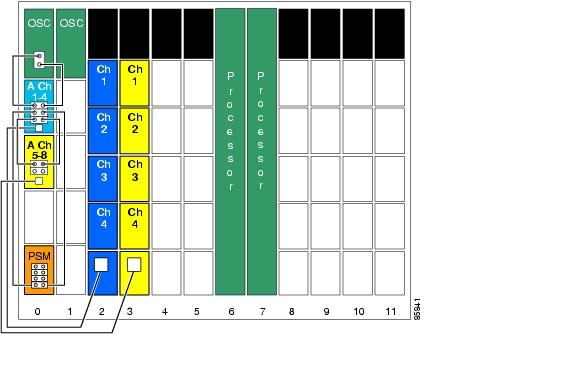
Figure 5-13 shows an example of how to cable a trunk fiber protected configuration.
Figure 5-13 Cabling Between 4-Channel Mux/Demux Modules and PSM for Line Card Protected Configurations
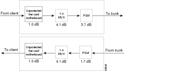
Figure 5-14 shows the optical power budget for a directly connected line card protected configuration.
Figure 5-14 Optical Power Budget for Trunk Fiber Protected Configurations
The PSM can also connect directly to a line card motherboard. That configuration would not include the loss for the mux/demux modules.
Point-to-Point Topologies
Use the following criteria in determining the equipment needed for a point-to-point topology:
•
•
•
•
There are many optical mux/demux module combinations that can satisfy the requirements of a network design. For example, a shelf can support 32 channels using eight 4-channel mux/demux modules, four 8-channel mux/demux modules, or one 32-channel mux/demux module. However, certain configurations can prove costly as network requirements change.
The terminal mux/demux modules are ideally suited for a point-to-point topology. They impose less optical link loss than cascading the 4-channel and 8-channel modules, thereby maximizing the distance between nodes. Price per channel is also less if the current or future channel requirement is near 32. However, if future plans include migrating to a ring environment, a terminal mux/demux module is not ideal. If, for example, a point-to-point topology using 32-channel mux/demux modules at each end were migrated to a hubbed ring, the node that became an add/drop node could not use the 32-channel module (though the hub node could use that module). If the migration were to a meshed ring, neither node could use the 32-channel module.
Note
Unprotected 16 Channel Point-to-Point Configuration with
10-Gbps Line Card MotherboardsFigure 5-15 shows the optical power loss for each of the components traversed by data channels 1 to 16 and for the OSC. This configuration uses an unprotected 10-Gbps line card motherboard. A fully populated shelf supports 16 channels in an unprotected configuration.
Figure 5-15 Optical Power Budget for Unprotected Point-to-Point Topology
with 10-Gbps Line Card Motherboard
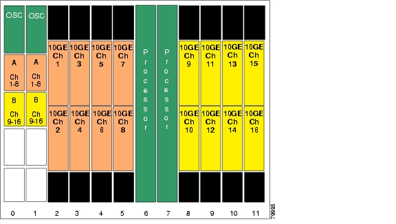
Figure 5-16 shows how the shelf for each node is populated to support a 16-channel unprotected configuration using 10-Gbps line card motherboards.
Figure 5-16 Shelf Configuration for Unprotected 16-Channel Point-to-Point Topology with
10-Gbps Line Card Motherboard
Protected 8-Channel Point-to-Point Configuration with
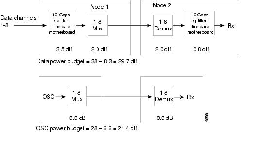
10-Gbps Line Card MotherboardsFigure 5-17 shows the optical power loss for each of the components traversed by data channels 1 to 8 and for the OSC. This configuration uses a protected 10-Gbps line card motherboard. A fully populated shelf supports 8 channels in a protected configuration.
Figure 5-17 Optical Power Budget for Protected Point-to-Point Topology
with 10-Gbps Line Card Motherboard
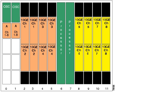
Figure 5-18 shows how the shelf for each node is populated to support a 8-channel protected configuration using 10-Gbps line card motherboards.
Figure 5-18 Shelf Configuration for Protected 8-Channel Point-to-Point Topology with
10-Gbps Line Card Motherboard
Unprotected 32-Channel Point-to-Point Configuration
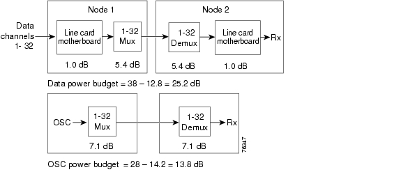
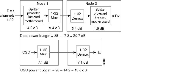
Figure 5-19 shows the optical power loss for each of the components traversed by data channels 1 to 8 and for the OSC. This configuration uses an unprotected line card motherboard.
Figure 5-19 Optical Power Budget for Unprotected Point-to-Point Topology
In an unprotected point-to-point topology, the Cisco ONS 15540 ESPx can support up to 32 unprotected channels on a single fiber pair.
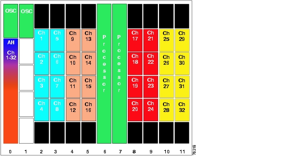
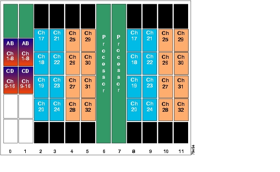
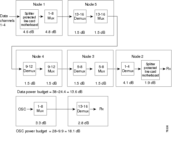
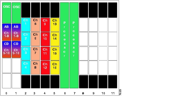
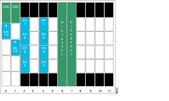
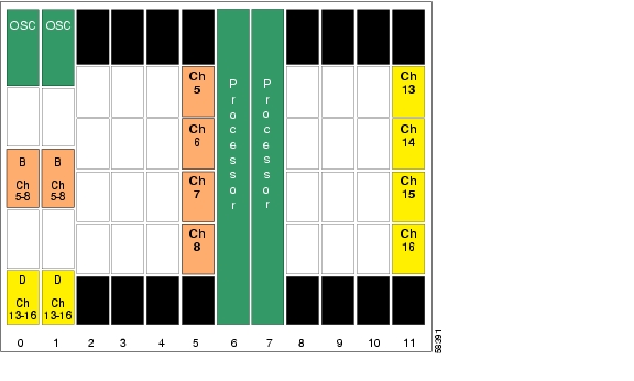
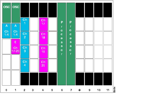
Figure 5-20 shows how the shelf for each node is populated to support a 32-channel unprotected configuration using one 32-channel mux/demux module. The line card motherboards are all unprotected. The line card motherboards in slots 2 to 5 cross connect to the mux/demux module in slot 0/0 and the line card motherboards in slots 8 to 11 cross connect to the mux/demux module in slot 0/2.
Figure 5-20 Shelf Configuration for Unprotected 32-Channel Point-to-Point Topology
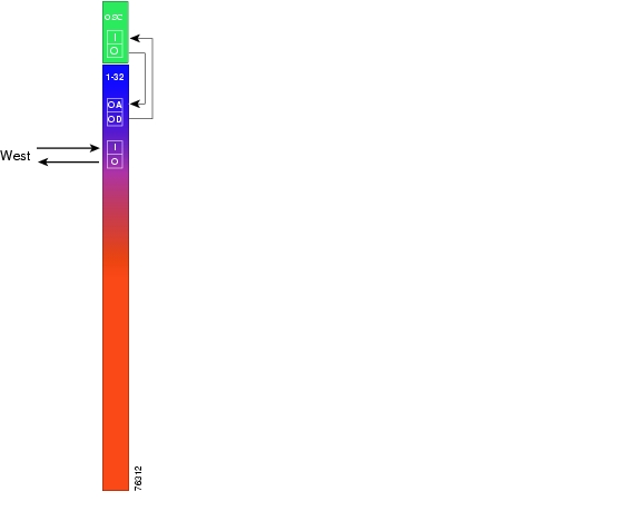
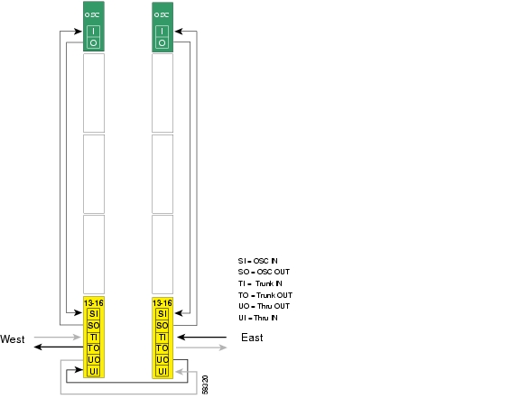
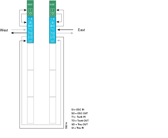
Figure 5-21 shows how the terminal mux/demux modules are cabled for the 32-channel unprotected point-to-point configuration.
Figure 5-21 Terminal Mux/Demux Module Cabling with OSC for Unprotected 32-Channel Point-to-Point Topology
Splitter Protected 32-Channel Point-to-Point Configuration
In a splitter protected point-to-point topology, the Cisco ONS 15540 ESPx can support up to 32 protected channels on two fiber pairs.
Figure 5-22 shows the optical power loss for each of the components traversed by data channels 17 to 32, which have the greatest amount of loss, and for the OSC. This configuration uses the splitter protected line card motherboards.
Figure 5-22 Optical Power Budget for Splitter Protected Point-to-Point Topology
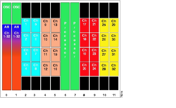
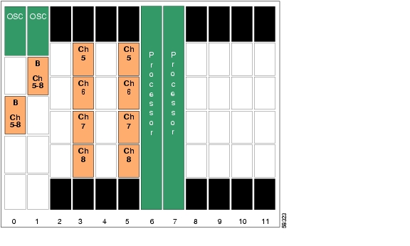
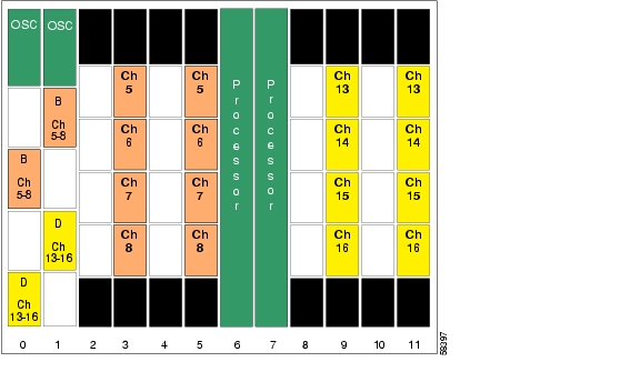
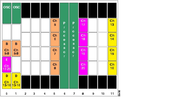
Figure 5-23 shows the shelf configuration for both nodes in a 32-channel splitter protected point-to-point topology. For splitter protection, the splitter protected line card motherboards are used, along with terminal mux/demux modules in both west and east mux/demux slots 0 and 1.
Figure 5-23 Shelf Configuration for Splitter Protected 32-Channel Point-to-Point Topology
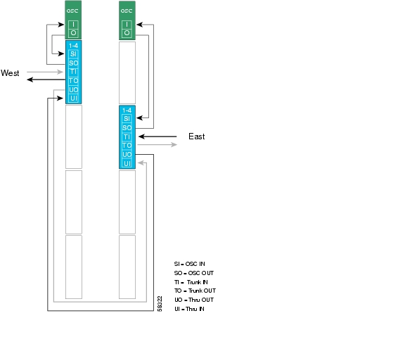
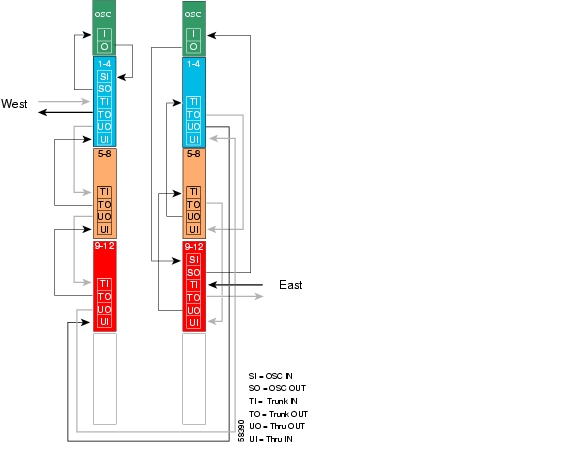
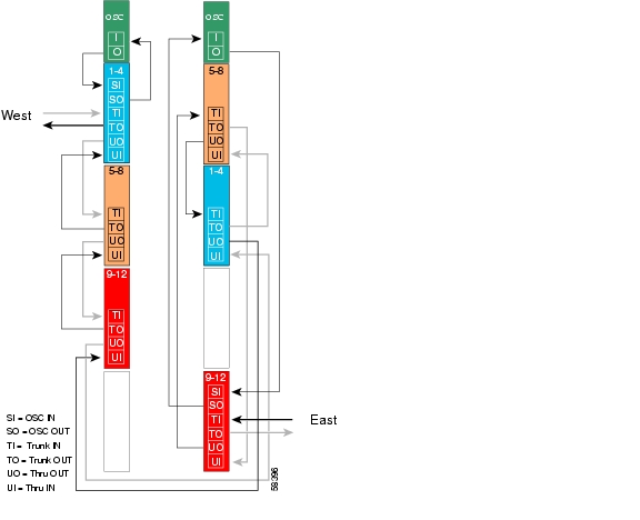
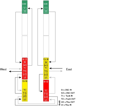
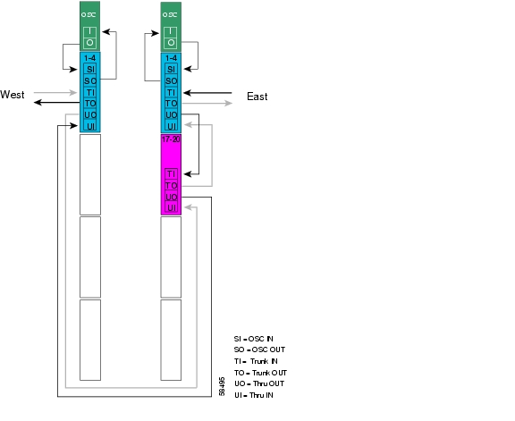
Figure 5-24 shows how the terminal mux/demux modules are cabled for the 32-channel splitter protected point-to-point configuration.
Figure 5-24 Terminal Mux/Demux Module Cabling with OSC for Splitter Protected 32-Channel Point-to-Point Topology
Line Card Protected 16-Channel Point-to-Point Configuration
In a line card protected point-to-point topology, a single Cisco ONS 15540 ESPx shelf can support up to 16 protected channels on two fiber pairs.
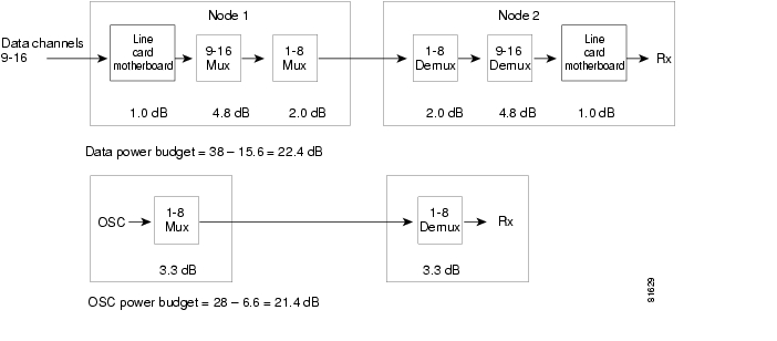
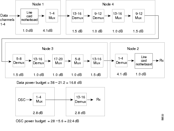
Figure 5-25 shows the optical power loss for each of the components traversed by the 16 data channels and the OSC, along with the resulting power budget. This configuration uses the east and unprotected line card motherboards.
Figure 5-25 Optical Power Budget for Line Card Protected 16-Channel Point-to-Point Topology
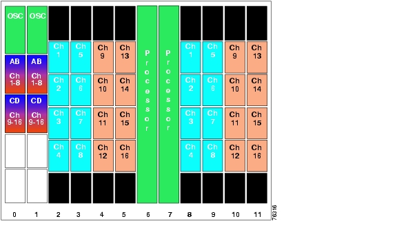
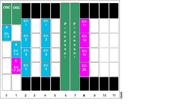
Figure 5-26 shows the shelf configuration for both nodes in a 16-channel line card protected point-to-point topology. For line card protection, the line card motherboards in slots 2 to 5 cross connect to the mux/demux modules in slots 0 and the line card motherboards in slots 8 to 11 cross connect to the mux/demux modules in slot 1.
Figure 5-26 Shelf Configuration for Line Card Protected 16-Channel Point-to-Point Topology
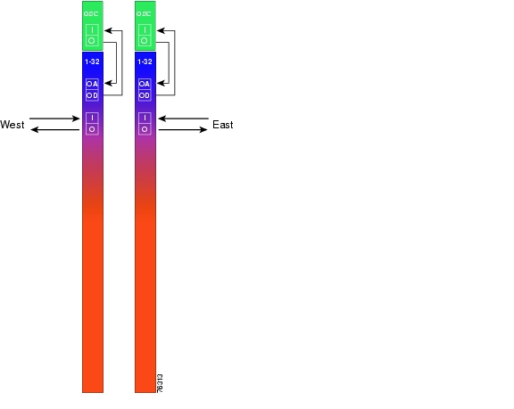
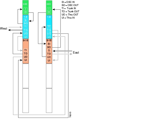
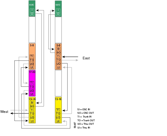
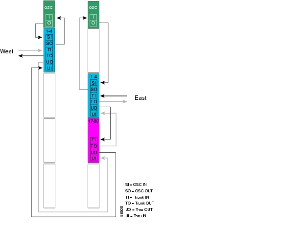
Figure 5-27 shows how the terminal mux/demux modules are cabled for the 16-channel line card protected point-to-point configuration.
Figure 5-27 Terminal Mux/Demux Module Cabling with OSC for Line Card Protected 16-Channel Point-to-Point Topology
Line Card Protected 32-Channel Point-to-Point Configuration
By cascading two Cisco ONS 15540 ESPx shelves, 32 channels can be supported in a line card protected point-to-point configuration. Shelf 1 is configured for channels 1 to 16 with OSC, while shelf 2 is configured for channels 17 to 32 without OSC. The terminal mux/demux modules are patched between the two shelves as if they were in the same shelf. In this configuration, shelf 2 cannot support the OSC, which means that a separate Ethernet connection to that shelf is required for management purposes.
The optical power budget for this configuration is the same as for a 32-channel unprotected configuration, shown in Figure 5-19.
Note
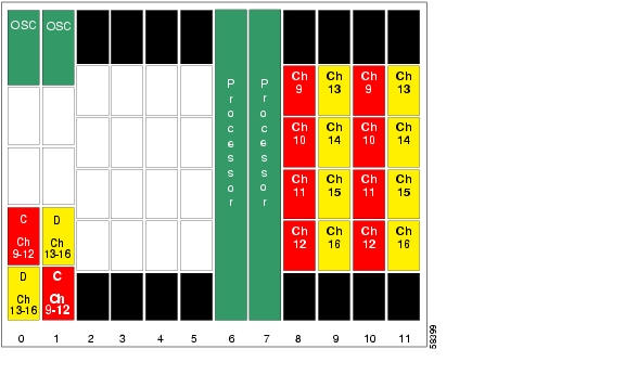
The configuration and terminal mux/demux cabling for shelf 1 in the line card protected 32-channel configuration are the same as for the line card protected 16-channel configuration, shown in Figure 5-26 and Figure 5-27. The configuration for shelf 2 is shown in Figure 5-28. As in shelf 1, the line card motherboards in slots 2 to 5 cross connect to the mux/demux modules in slot 0 and the line card motherboards in slots 8 to 11 cross connect to the mux/demux modules in slot 1.
Figure 5-28 Shelf 2 Configuration for Line Card Protected 32-Channel Point-to-Point Topology
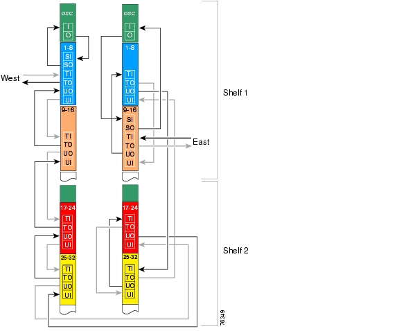
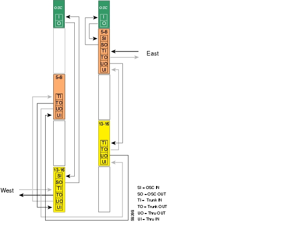
Figure 5-29 shows how the terminal mux/demux modules are cabled between the two shelves to support all 32 channels on both the east and west sides.
Figure 5-29 Terminal Mux/Demux Module Cabling with Two Shelves for Line Card Protected 32-Channel Point-to-Point Topology
Hubbed Ring Topologies
In a hubbed ring architecture, one node serves as the hub (or terminal) node, while all other nodes perform add/drop functions. This type of topology is also sometimes called hub and spoke, because each of the spoke nodes is logically connected to only the hub node. In a hubbed ring, the hub can use terminal mux/demux modules, while each of the spoke nodes must be equipped with add/drop mux/demux modules.
Note
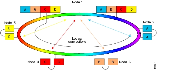
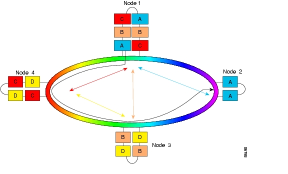
Figure 5-30 shows the channel plan for a 16-channel hubbed ring where a band of four channels is dropped at each spoke node. The hub node in this example uses two 8-channel add/drop mux/demux modules. The nodes communicate as follows:
•
•
•
•
Figure 5-30 Hubbed Ring Channel Plan
Splitter Protected Hubbed Ring Configuration
Assuming that all nodes were equidistant in the ring, the path with the greatest optical link loss (the "worst path") would be the path for band A between node 1 and node 2. This path is shown in Figure 5-30 by the black line connecting node 1 to node 2 by way of nodes 5, 4, and 3.
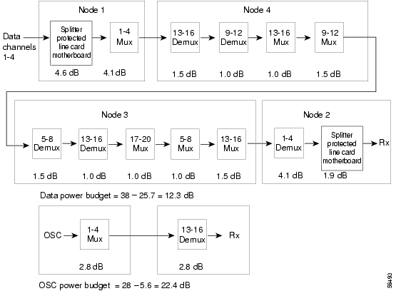
Figure 5-31 shows the optical power loss through each of the components from node 1 to node 2 for band A, and for the OSC. This configuration uses the splitter protected line card motherboards.
Figure 5-31 Optical Power Budget for Splitter Protected Hubbed Ring
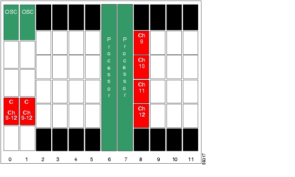
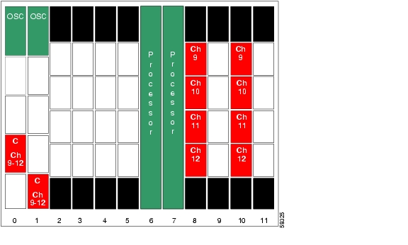
Figure 5-32 shows how the hub node shelf is populated in the 16-channel splitter protected hubbed ring topology. Splitter protected line card motherboards are installed in slots 2 to 5, and two 8-channel add/drop mux/demux modules are used in the west and east mux/demux slots 0 and 1. Each line card motherboard cross connects to both mux/demux modules.
Figure 5-32 Shelf Configuration for 16-Channel Hub Node in Splitter Protected Hubbed Ring
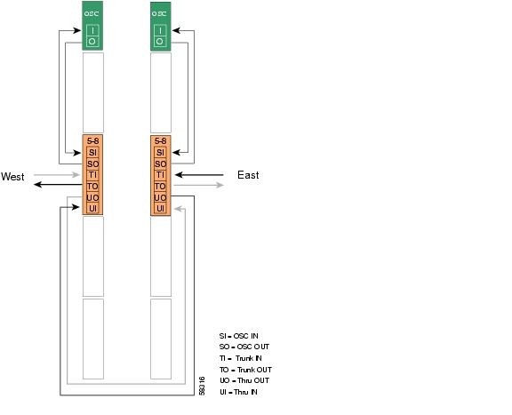
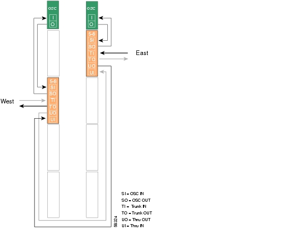
Figure 5-33 shows how the 8-channel add/drop mux/demux modules are cabled for the hub node in the splitter protected hubbed ring.
Figure 5-33 Add/Drop Mux/Demux Module Cabling with OSC for 16-Channel Hub Node in Splitter Protected Hubbed Ring
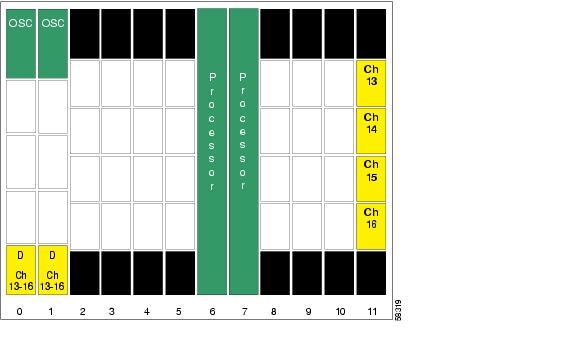
Figure 5-34 shows the shelf configuration for node 2 in the hubbed ring. A splitter protected line card motherboard is used in slot 2, and 4-channel mux/demux modules are used in subslot 0 of the west and east mux/demux slots 0 and 1. The line card motherboard cross connects to both mux/demux modules.
Figure 5-34 Shelf Configuration for Node 2 in Splitter Protected Hubbed Ring
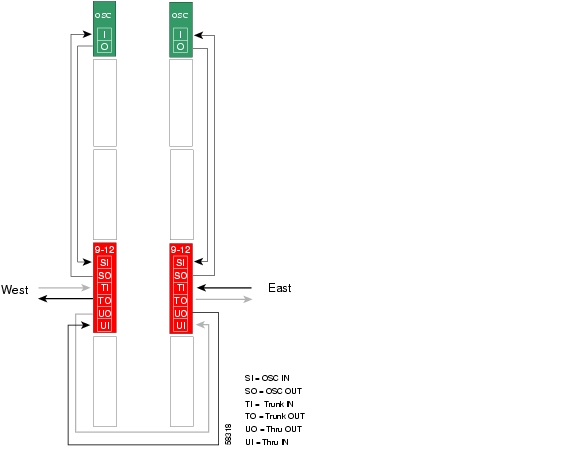
Figure 5-35 shows how the 4-channel mux/demux modules are cabled for node 2 in the splitter protected hubbed ring.
Figure 5-35 Add/Drop Mux/Demux Module Cabling with OSC for Node 2 in Splitter Protected Hubbed Ring
Figure 5-36 shows the shelf configuration for node 3 in the hubbed ring. A splitter protected line card motherboard is used in slot 5, and 4-channel mux/demux modules are used in subslot 1 of the west and east mux/demux slots 0 and 1. The line card motherboard cross connects to both mux/demux modules.
Figure 5-36 Shelf Configuration for Node 3 in Splitter Protected Hubbed Ring
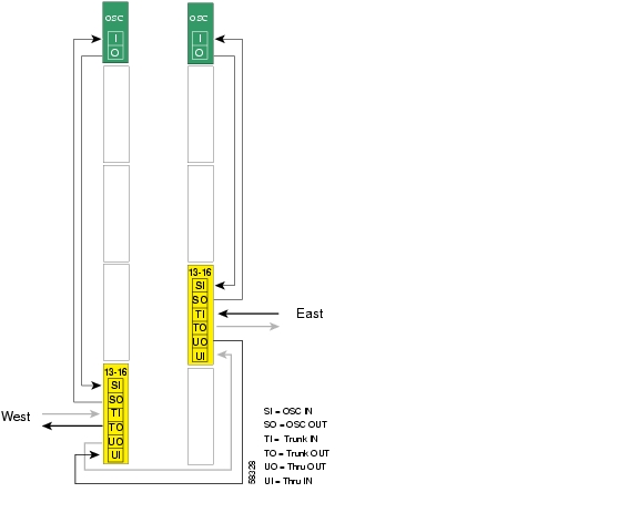
Figure 5-37 shows how the 4-channel mux/demux modules are cabled for node 3 in the splitter protected hubbed ring.
Figure 5-37 Add/Drop Mux/Demux Module Cabling with OSC for Node 3 in Splitter Protected
Hubbed Ring
Figure 5-38 shows the shelf configuration for node 4 in the hubbed ring. A splitter protected line card motherboard is used in slot 8, and 4-channel mux/demux modules are used in subslot 2 of the west and east mux/demux slots 0 and 1. The line card motherboard cross connects to both mux/demux modules.
Figure 5-38 Shelf Configuration for Node 4 in Splitter Protected Hubbed Ring
Figure 5-39 shows how the 4-channel mux/demux modules are cabled for node 4 in the splitter protected hubbed ring.
Figure 5-39 Add/Drop Mux/Demux Module Cabling with OSC for Node 4 in Splitter Protected
Hubbed Ring
Figure 5-40 shows the shelf configuration for node 5 in the hubbed ring. A splitter protected line card motherboard is used in slot 11, and 4-channel mux/demux modules are used in subslot 3 of the west and east mux/demux slots 0 and 1. The line card motherboard cross connects to both mux/demux modules.
Figure 5-40 Shelf Configuration for Node 5 in Splitter Protected Hubbed Ring
Figure 5-41 shows how the 4-channel mux/demux modules are cabled for node 5 in the splitter protected hubbed ring.
Figure 5-41 Add/Drop Mux/Demux Module Cabling with OSC for Node 5 in Splitter Protected
Hubbed Ring
Line Card Protected Hubbed Ring Configuration
With line card protection, a single Cisco ONS 15540 ESPx shelf can support a maximum of 16 channels at the hub node in a hubbed ring. Using two cascaded shelves, 32 channels can be supported. The configuration for the two shelves that form the hub node is the same as the one described in the "Line Card Protected 32-Channel Point-to-Point Configuration" section.
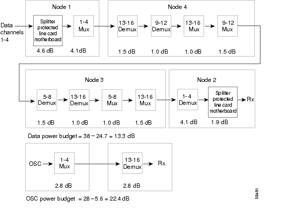
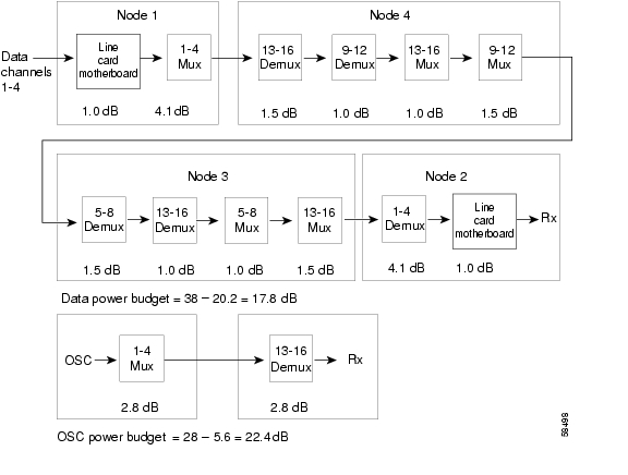
Figure 5-42 shows the optical power budget for the hubbed ring with line card protection. The figure shows the optical power loss for each of the components traversed by the channels in band A from node 1 to node 2 over nodes 5, 4, and 3 (see Figure 5-30). Assuming that the nodes are equidistant, this would be the worst path. This configuration uses the east and unprotected line card motherboards.
Figure 5-42 Optical Power Budget for Line Card Protected Hubbed Ring
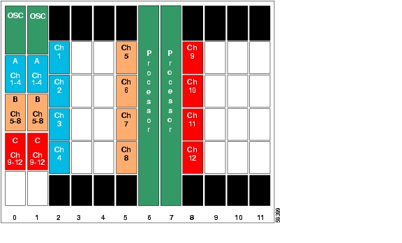
Figure 5-43 shows the shelf configuration for the hub node in this hubbed ring example. The line card motherboards in slots 2 to 5 are unprotected motherboards that cross connect to the 8-channel add/drop mux/demux modules in the west mux/demux slot 0; the line card motherboards in slots 8 to 11 are unprotected motherboards that cross connect to the 8-channel add/drop mux/demux modules in the east mux/demux slot 1.
Figure 5-43 Shelf Configuration for Hub Node in Line Card Protected Hubbed Ring
Figure 5-44 shows how the 8-channel mux/demux modules are cabled for the hub node in the line card protected hubbed ring.
Figure 5-44 Add/Drop Mux/Demux Module Cabling with OSC for Hub Node in Line Card Protected Hubbed Ring
Figure 5-45 shows the shelf configuration for node 2 in the line card protected hubbed ring. Slot 2 uses an unprotected line card motherboard that cross connects to the add/drop mux/demux module in the west mux/demux slot 0; slot 4 uses an unprotected line card motherboard that cross connects to the add/drop mux/demux module in the east mux/demux slot 1.
Figure 5-45 Shelf Configuration for Node 2 in Line Card Protected Hubbed Ring
Figure 5-46 shows how the 4-channel mux/demux modules are cabled for node 2 in the line card protected hubbed ring.
Figure 5-46 Add/Drop Mux/Demux Module Cabling with OSC for Node 2 in Line Card Protected Hubbed Ring
Figure 5-47 shows the shelf configuration for node 3 in the hubbed ring. Slot 3 uses an unprotected line card motherboard that cross connect to the add/drop mux/demux module in the east mux/demux slot 1; slot 5 uses an unprotected line card motherboard that cross connect to the add/drop mux/demux module in the west mux/demux slot 0.
Figure 5-47 Shelf Configuration for Node 3 in Line Card Protected Hubbed Ring
Figure 5-48 shows how the 4-channel mux/demux modules are cabled for node 3 in the line card protected hubbed ring.
Figure 5-48 Add/Drop Mux/Demux Module Cabling with OSC for Node 3 in Line Card Protected Hubbed Ring
Figure 5-49 shows the shelf configuration for node 4 in the line card protected hubbed ring. Slot 8 uses an unprotected line card motherboard that cross connect to the add/drop mux/demux module in the west mux/demux slot 0; slot 10 uses an unprotected line card motherboard that cross connect to the add/drop mux/demux module in the east mux/demux slot 1.
Figure 5-49 Shelf Configuration for Node 4 in Line Card Protected Hubbed Ring
Figure 5-50 shows how the 4-channel mux/demux modules are cabled for node 4 in the line card protected hubbed ring.
Figure 5-50 Add/Drop Mux/Demux Module Cabling with OSC for Node 4 in Line Card Protected Hubbed Ring
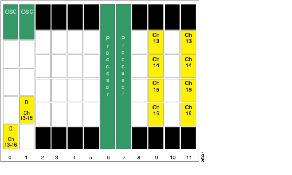
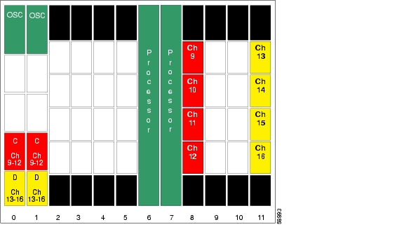
Figure 5-51 shows the shelf configuration for node 5 in the line card protected hubbed ring. Slot 9 uses an unprotected line card motherboard that cross connect to the add/drop mux/demux module in the east mux/demux slot 1; slot 11 uses an unprotected line card motherboard that cross connect to the add/drop mux/demux module in the west mux/demux slot 0.
Figure 5-51 Shelf Configuration for Node 5 in Line Card Protected Hubbed Ring
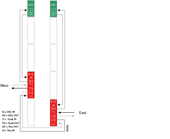
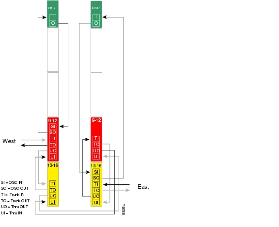
Figure 5-52 shows how the 4-channel mux/demux modules are cabled for node 5 in the line card protected hubbed ring.
Figure 5-52 Add/Drop Mux/Demux Module Cabling with OSC for Node 5 in Line Card Protected Hubbed Ring
Meshed Ring Topologies
As explained in the "Meshed Ring" section, in a full logical mesh, every node can communicate with every other node. In some cases, this is not necessary and a partial mesh is formed.
Note
Figure 5-53 shows the channel plan for a 16-channel partial meshed ring. The nodes communicate as follows:
•
•
•
•
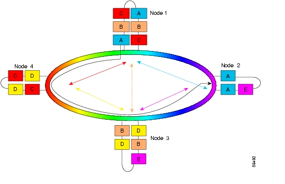
Figure 5-53 Channel Plan for Meshed Ring
Band allocation and the ordering of the optical mux/demux modules becomes especially important in a mesh environment because of the increased possibility of multiple mux/demux modules at a particular node. The example in Figure 5-53 shows the network configured exclusively with 4-channel add/drop mux/demux modules.
Band allocation can have an effect on both the cost and optical power budget of the network. In this example, it is possible to replace the 4-channel mux/demux modules for bands A and B in node 1 with the 8-channel AB band mux/demux modules. Likewise, the 4-channel mux/demux modules in node 4 could be replaced with 8-channel modules. The effect of this swap would be to lower the cost, but also to decrease the optical power budget, as the add and drop loss for an 8-channel module is greater than that for a 4-channel module.
The concept of ordering can become prominent in mesh topologies. As indicated by the black line in Figure 5-53, the path with the most loss (assuming equidistant nodes on the ring) is the one for band A from the west mux/demux motherboard of node 1 to the east mux/demux motherboard of node 2, traversing nodes 4 and 3. Notice that in the west direction the add/drop mux/demux module for band A on node 1 is positioned closer to the trunk than bands B or C. As a result, band A does not pass through any of the other add/drop mux/demux modules located at node 1. Band B channels must pass through the band A mux/demux, while band C must pass through the mux/demux modules for both band B and band A.
Splitter Protected Meshed Ring Configuration
Figure 5-54 shows the optical power loss for each of the components traversed by the channels in band A from node 1 to node 2 over nodes 4 and 3. This configuration uses the splitter protected line card motherboards.
Figure 5-54 Optical Power Budget for Splitter Protected Meshed Ring
Figure 5-55 shows the shelf configuration for node 1 in the splitter protected meshed ring. Splitter protected line card motherboards are used to cross connect the signal to the add/drop mux/demux modules in both west and east mux/demux slots 0 and 1.
Figure 5-55 Shelf Configuration for Node 1 in Splitter Protected Meshed Ring
Figure 5-56 shows how the 4-channel mux/demux modules are cabled for node 1 in the splitter protected meshed ring.
Figure 5-56 Add/Drop Mux/Demux Module Cabling with OSC for Node 1 in Splitter Protected Meshed Ring
Figure 5-57 shows the shelf configuration for node 2 in the splitter protected meshed ring. Slot 2 uses the splitter protected line card motherboard, which cross connects the signal to the add/drop mux/demux modules in both west and east mux/demux slots 0 and 1.
Figure 5-57 Shelf Configuration for Node 2 in Splitter Protected Meshed Ring
Figure 5-58 shows how the 4-channel mux/demux modules are cabled for node 2 in the splitter protected meshed ring.
Figure 5-58 Add/Drop Mux/Demux Module Cabling with OSC for Node 2 in Splitter Protected Meshed Ring
Figure 5-59 shows the shelf configuration for node 3 in the splitter protected meshed ring. Slots 5 and 11 use splitter protected line card motherboards, which cross connect the signal to the add/drop mux/demux modules in both west and east mux/demux slots 0 and 1.
Figure 5-59 Shelf Configuration for Node 3 in Splitter Protected Meshed Ring
Figure 5-60 shows how the 4-channel mux/demux modules are cabled for node 3 in the splitter protected meshed ring.
Figure 5-60 Add/Drop Mux/Demux Module Cabling with OSC for Node 3 in Splitter Protected Meshed Ring
Figure 5-61 shows the shelf configuration for node 4 in the splitter protected meshed ring. Slots 8 and 11 use the splitter protected line card motherboards, which cross connect the signal to the add/drop mux/demux modules in both the west and east mux/demux slots 0 and 1.
Figure 5-61 Shelf Configuration for Node 4 in Splitter Protected Meshed Ring
Figure 5-62 shows how the 4-channel mux/demux modules are cabled for node 4 in the splitter protected meshed ring.
Figure 5-62 Add/Drop Mux/Demux Module Cabling with OSC for Node 4 in Splitter Protected Meshed Ring
Line Card Protected Meshed Ring Configuration
Figure 5-63 shows the optical power budget for the hubbed ring with line card protection. The figure shows the optical power loss for each of the components traversed by the channels in band A between node 1 and node 2 over node 4 and node 3 (see Figure 5-53). Assuming the nodes in the ring are equidistant, this would be the worst path. This configuration uses the east and unprotected line card motherboards.
Figure 5-63 Optical Power Budget for Line Card Protected Meshed Ring
Figure 5-64 shows the shelf configuration for node 1 using line card protection in the example meshed ring. Slots 2, 5, and 8 use unprotected line card motherboards that cross connect to the add/drop mux/demux modules in the west mux/demux slot 0; slots 3, 4, and 10 use unprotected line card motherboards that cross connect to the add/drop mux/demux modules in the east mux/demux slot 1.
Figure 5-64 Shelf Configuration for Node 1 in Line Card Protected Meshed Ring
Figure 5-65 shows how the 4-channel mux/demux modules are cabled for node 1 in the line card protected meshed ring.
Figure 5-65 Add/Drop Mux/Demux Module Cabling with OSC for Node 1 in Line Card Protected Meshed Ring
Figure 5-66 shows the shelf configuration for node 2 in the line card protected meshed ring. Slot 2 uses an unprotected line card motherboard that cross connects to the add/drop mux/demux module in the west mux/demux slot 0; slot 4 uses an unprotected line card motherboard that cross connects to the add/drop mux/demux module in the east mux/demux slot 1.
Figure 5-66 Shelf Configuration for Node 2 in Line Card Protected Meshed Ring
Figure 5-67 shows how the 4-channel mux/demux modules are cabled for node 2 in the line card protected meshed ring.
Figure 5-67 Add/Drop Mux/Demux Module Cabling with OSC for Node 2 in Line Card Protected Meshed Ring
Figure 5-68 shows the shelf configuration for node 3 in the line card protected meshed ring. Slots 5 and 11 use unprotected line card motherboards that cross connect to the add/drop mux/demux modules in the west mux/demux slot 0; slots 3 and 9 use unprotected line card motherboards that cross connect to the add/drop mux/demux modules in the east mux/demux slot 1.
Figure 5-68 Shelf Configuration for Node 3 in Line Card Protected Meshed Ring
Figure 5-69 shows how the 4-channel mux/demux modules are cabled for node 3 for the line card protected meshed ring.
Figure 5-69 Add/Drop Mux/Demux Module Cabling with OSC for Node 3 in Line Card Protected Meshed Ring
Figure 5-70 shows the shelf configuration for node 4 in the line card protected meshed ring. Slots 8 and 11 use unprotected line card motherboards that cross connect to the add/drop mux/demux modules in the west mux/demux slots 0; slots 9 and 10 use unprotected line card motherboards that cross connect to the add/drop mux/demux modules in the east mux/demux slot 1.
Figure 5-70 Shelf Configuration for Node 4 in Line Card Protected Meshed Ring
Figure 5-71 shows how the 4-channel mux/demux modules are cabled for node 4 in the line card protected meshed ring.
Figure 5-71 Add/Drop Mux/Demux Module Cabling with OSC for Node 4 in Line Card Protected Meshed Ring
Meshed Ring Topologies with Unprotected Channels
It is possible to configure a ring in which one or more bands are unprotected. If a splitter protected or line card protected ring topology has already been configured, adding unprotected channels is straightforward.
To add unprotected channels to an existing ring configuration, follow these steps:
Step 1
Step 2
Step 3
Note
Splitter Protected Meshed Ring with Unprotected Channels Configuration
Figure 5-72 uses the same channel plan as the 16-channel partial meshed ring example (see the "Meshed Ring Topologies" section), but adds an unprotected band between node 2 and node 3. The nodes communicate as follows:
•
•
•
•
•
Figure 5-72 Channel Plan for Splitter Protected Meshed Ring with Unprotected Channels
Figure 5-73 shows the optical power loss for each of the components traversed by the channels in band A between node 1 and node 2 over node 4 and node 3, and for the OSC. All nodes use the 4-channel mux/demux modules.
Figure 5-73 Optical Power Budget for Splitter Protected Meshed Ring with Unprotected Channels
The shelf configuration and optical mux/demux module cabling for node 1 and node 4 are the same as for the 16-channel partial meshed ring example with splitter protection. See the following figures for these configurations:
•
•
•
•
Figure 5-74 shows the shelf configuration for node 2 in the splitter protected meshed ring with unprotected channels. Slot 2 uses the splitter protected line card motherboard, which cross connects the signal to the add/drop mux/demux modules in subslot 0 of both west and east mux/demux slots 0 and 1. Slot 4, which supports the unprotected channels, uses an unprotected line card motherboard.
Figure 5-74 Shelf Configuration for Node 2 in Splitter Protected Meshed Ring with Unprotected Channels
Figure 5-75 shows how the 4-channel mux/demux modules are cabled for node 2 in the splitter protected meshed ring with unprotected channels.
Figure 5-75 Add/Drop Mux/Demux Module Cabling for Node 2 in Splitter Protected Meshed Ring with Unprotected Channels
Figure 5-76 shows the shelf configuration for node 3 in the splitter protected meshed ring with unprotected channels. Slot 5 and slot 11 use splitter protected line card motherboards, which cross connect the signal to the add/drop mux/demux modules in subslot 1 and subslot 3, respectively, of both west and east mux/demux slots 0 and 1. Slot 8, which supports the unprotected channels, uses an unprotected line card motherboard.
Figure 5-76 Shelf Configuration for Node 3 in Splitter Protected Meshed Ring with Unprotected Channels
Figure 5-77 shows how the 4-channel mux/demux modules are cabled for node 3 in the splitter protected meshed ring with unprotected channels.
Figure 5-77 Add/Drop Mux/Demux Module Cabling for Node 3 in Splitter Protected Meshed Ring with Unprotected Channels
Line Card Protected Meshed Ring with Unprotected Channels Configuration
The topology and channel plan described in the "Meshed Ring Topologies with Unprotected Channels" section and shown in Figure 5-72 can be configured with line card protection.
Figure 5-78 shows the optical power loss for each of the components traversed by the channels in band A between node 1 and node 2 over node 4 and node 3, and for the OSC. All nodes use the 4-channel mux/demux modules. The unprotected line card motherboards are used.
Figure 5-78 Optical Power Budget for Line Card Protected Meshed Ring with Unprotected Channels
The shelf configuration and optical mux/demux cabling for node 1 and node 4 are the same as for the 16-channel partial meshed ring example with line card protection. See the following figures for these configurations:
•
•
•
•
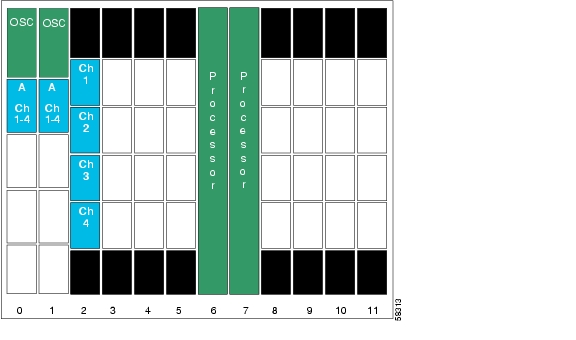
Figure 5-79 shows the shelf configuration for node 2 in the line card protected meshed ring with unprotected channels. Channels 1 to 4 are line card protected using an unprotected line card motherboard in slot 2 and an unprotected line card motherboard in slot 4. Slot 8 uses an unprotected line card motherboard for the unprotected channels.
Figure 5-79 Shelf Configuration for Node 2 in Line Card Protected Meshed Ring with Unprotected Channels
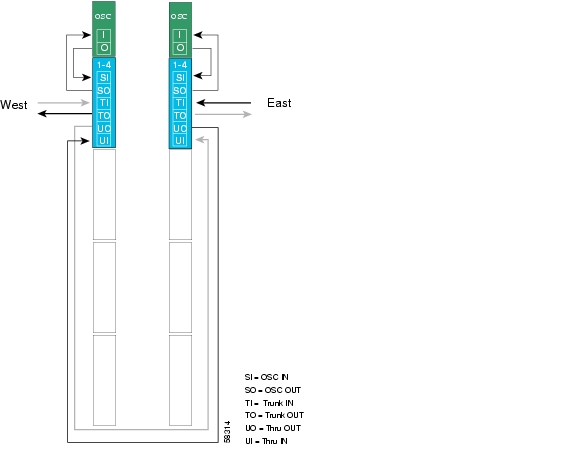
Figure 5-80 shows how the 4-channel mux/demux modules are cabled for node 2 in the line card protected meshed ring with unprotected channels.
Figure 5-80 Add/Drop Mux/Demux Module Cabling for Node 2 in Line Card Protected Meshed Ring with Unprotected Channels
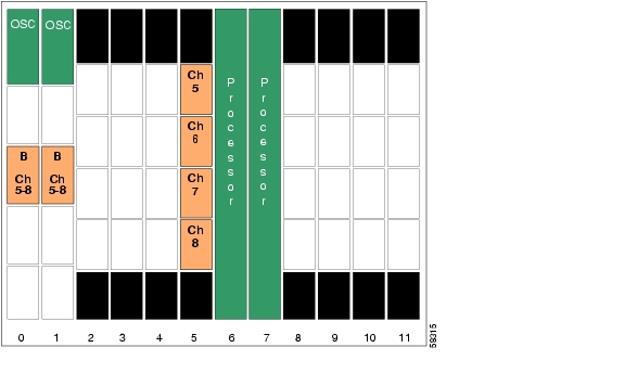
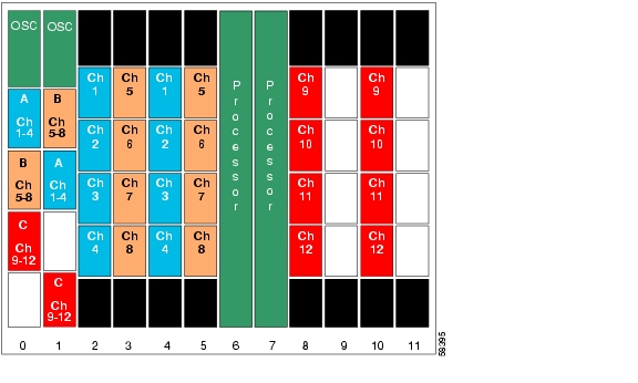
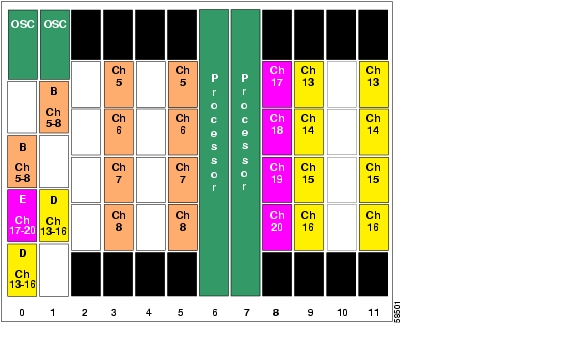
Figure 5-81 shows the shelf configuration for node 3 in the line card protected meshed ring with unprotected channels. Channels 5-8 are line card protected using an unprotected line card motherboard in slot 3 and an unprotected line card motherboard in slot 5. Channels 13-16 are line card protected using an unprotected line card motherboard in slot 9 and an unprotected line card motherboard in slot 11. Slot 8 uses an unprotected line card motherboard for the unprotected channels.
Figure 5-81 Shelf Configuration for Node 3 in Line Card Protected Meshed Ring with Unprotected Channels
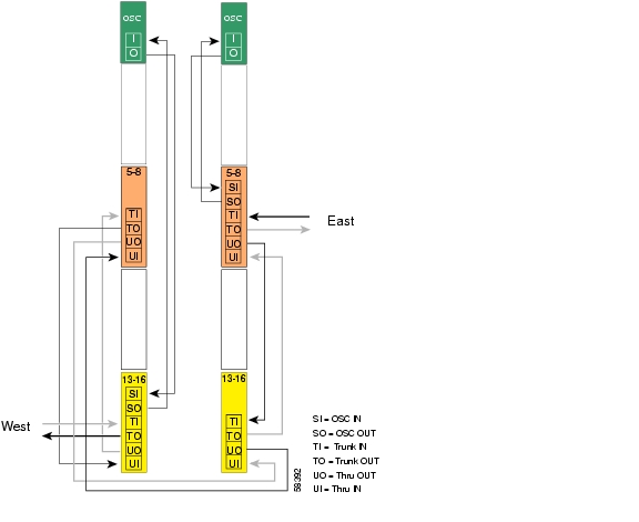
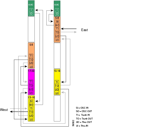
Figure 5-82 shows how the 4-channel mux/demux modules are cabled for node 3 in the line card protected meshed ring with unprotected channels.
Figure 5-82 Add/Drop Mux/Demux Module Cabling for Node 3 in Line Card Protected Meshed Ring with Unprotected Channels
![]()
![]()
![]()
![]()
![]()
![]()
![]()
![]()
Posted: Tue Jan 25 15:13:22 PST 2005
All contents are Copyright © 1992--2005 Cisco Systems, Inc. All rights reserved.
Important Notices and Privacy Statement.