|
|

This document lists and describes system alarms and error messages for the Cisco ONS 15540 ESPx. The system software sends these alarms and error messages to the console (and, optionally, to a logging server on another system) during operation. Not all error messages indicate problems with your system. Some are purely informational, while others might help diagnose problems with links, internal hardware, or the system software.
This document includes the following sections: ·
System alarms are associated with a physical entity such as a module or the chassis. Unlike simple error messages, the state of an alarm persists until an assert or clear event changes its state.
When an alarm state changes, you see an associated error message describing whether the alarm is asserted or cleared. The associated error message also displays the severity and description of the entity plus the alarm type.
You can display the current state of alarms by using the show facility-alarm status command on the active processor card, as in the following example:
 |
Note The number that appears at the end of the description is the index of the alarm. |
The list of system alarms and error messages is organized according to the system facility that produces the messages, in alphabetical order. Within each system facility section, messages are listed alphabetically by mnemonics. Each error message is followed by an explanation and a recommended action. System alarms and error messages appear only when the system remains operational.
Error message severity levels correspond to the keywords assigned by the logging global configuration commands that define where and at what level these messages appear. The default is to log messages to the console at the debugging level (7).
System error messages begin with a percent sign and are structured as follows:
FACILITY is a code consisting of two or more uppercase letters that indicate the facility to which the alarm or error message refers. A facility is a hardware device, a protocol, or a module of the system software. Table 1 lists some system facility codes.
|
System alarm SEVERITY codes range from 0 to 3 and reflect the severity of the alarm. The lower the number, the more serious the alarm. Table 2 lists the severity levels.
Error message SEVERITY codes range from 0 to 7 and reflect the severity of the condition. The lower the number, the more serious the situation. Table 3 lists the severity levels.
MNEMONIC is a code that uniquely identifies the error message.
Message-text is a text string that describes the condition. This portion of the message might contain detailed information about the event, including terminal port numbers, network addresses, or addresses that correspond to locations in the system memory address space. Because the information in these variable fields changes from message to message, it is represented here by short strings enclosed in square brackets ([ ]). A decimal number, for example, is represented as [dec].
Table 4 lists the representations of variable fields and the type of information in the fields.
The following example error message shows how the variable field might be used:
Table 4 Representation of Variable Fields in Alarms and Error Messages
|
The following example shows how to interpret an error message:
%APS-1-NO_ACTIVE: No Active Port In Group [chars]
Facility code = APS (indicating that it is APS sub system specific error)
Severity = 1 (severity of the alarm/event)
Description of the problem = No Active Port In Group [chars]
[chars] is the actual APS group name when output on the console.
When the term "ingress" appears in an error message it refers to client interfaces and the fault is associated with the client equipment. This term appears in the following example:
%LCMDC-3-FH_ILOSY_ALM: Ingress FC/ESCON Loss of Sync; Slot [dec] Subcard [dec] Port [dec]
When the term "egress" appears in an error message it refers to a transponder wave interface on the trunk side, and the fault originates from the remote node. This term appears in the following example:
%LCMDC-3-ECDRLK_ALM : Egress CDR Locking error; Slot [dec] Subcard [dec] Port [dec]
A number of messages describe internal errors and contain traceback information. This information is very important and should be included when you report a problem to your technical support representative.
The following sample error message includes traceback information:
-Process= "Exec", level= 0, pid= 17

-Traceback= 1A82 1AB4 6378 A072 1054 1860
This section describes how to troubleshoot a problem using the system alarms and error messages generated by the system. To demonstrate this process, a simple point-to-point network example is used to highlight the information that is available to diagnose the cause of link failures.
The following examples do not demonstrate all alarm conditions that might appear in Cisco ONS 15540 ESPx networks caused by hardware defects or failure. Alarms might be symptoms of standard operating procedures. For example, a Cisco ONS 15540 ESPx provisioned with 32 channels can generate multiple traps to a network management system indicating a receive loss of light or loss of signal on all 32 channels. These traps might be caused by a catastrophic site disaster, or they might be caused by scheduled maintenance on another site or by changes are that occurring in the Cisco ONS 15540 ESPx network.
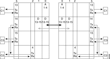
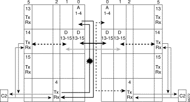
The network example shown in Figure 1 supports three client signals and four channels. The nodes in the example are called Manhattan and Brooklyn.
Table 5 summarizes the channels, client signal protocols, and protection schemes for the channel signals.
Table 5 Channels, Protocols, and Protection Schemes for Example Network
|
|
1 GE = Gigabit Ethernet 2 FC = Fibre Channel |
Table 6 shows the Rx power values at both the client side and the trunk side of the transponder modules. We recommend creating a similar table when you turn up your network. Also, issue the service timestamps log datetime and service timestamps debug datetime [msec] global configuration commands to include the current time in all console log messages. Millisecond (msec) granularity is optional.
|
Note The transparent interface is the client side port of the transponder module. The wavepatch and wave interfaces are trunk side transmit and receive interfaces on the transponder module. |
|
Note The OSC (Optical Supervisory Channel) supports bidirectional APS communication in the example network. |
Table 6 Receive Power Values for the Example Network
Use the show connect intermediate command to display the complete path for the channel.
It is important to understand what "good" status is for the channel links and attached devices on a Cisco ONS 15540 ESPx system. Ensure that the following conditions are met:
The event messages are displayed instantly on the console, by default, or are redirected to an internal buffer, a nonconsole terminal (using Telnet), or a syslog server. All alarms and events can also be redirected as traps to network management systems that support Simple Network Management Protocol (SNMP).
The logging buffered buffer-size global configuration command enables copying of log messages to an internal buffer and optionally sets the size of the buffer. This buffer is circular, so newer messages overwrite older messages after the buffer is full. The default buffer size is 131072 bytes. To display the messages that are logged in the buffer, use the show logging EXEC command. The first message displayed is the oldest message in the buffer. To clear the current contents of the buffer, use the clear logging privileged EXEC command.
The terminal monitor EXEC command locally accomplishes the task of displaying the system error messages to a nonconsole terminal (using ).
The logging host-name command identifies a syslog server host to receive logging messages. The host-name argument is the name or Internet address of the host. By issuing this command more than once, you build a list of syslog servers that receive logging messages. The no logging host-name command deletes the syslog server with the specified address from the list of syslogs.
If you are using a network management system to receive traps, then you must enable traps. Use the following global configuration commands:
|
Systems that support SNMP often need a mechanism for recording notification information if notifications are lost when retransmission limits are exceeded. The notification log MIB provides a common infrastructure for other MIBs in the form of a local logging function. Use the following global configuration command to enable MIB logging:
|
|
Note For more information on event logging and SNMP, refer to the Cisco IOS Configuration Fundamentals Configuration Guide and the Cisco IOS Configuration Fundamentals Command Reference . |
This section contains examples of channel failures in the example network shown in Figure 1.
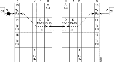
In this example, an FC client device connected to a transponder module goes down on the Manhattan system. The FC client equipment is connected to transparent interface 5/0/0.
Figure 2 shows the location of the failure.
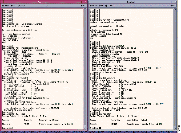
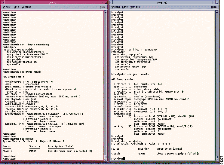
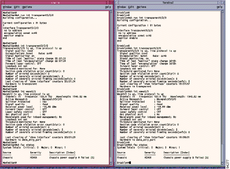
Figure 3 shows the interface status before the failure occurred. It shows that the interface is Up, the signal quality is Good, and there are no alarms related to this interface.
|
Note Ignore the MINOR alarm that indicates that the shelf does not have a redundant power supply. |
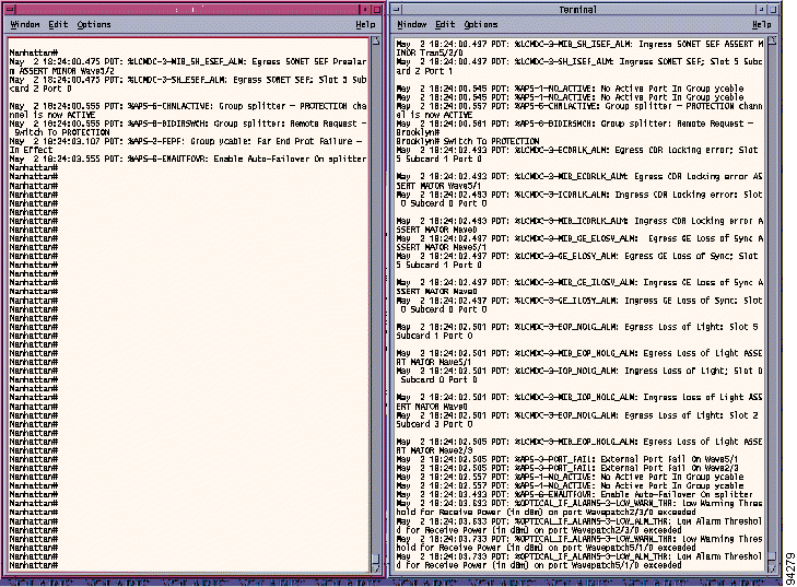
The first indications of a failure might be the following:
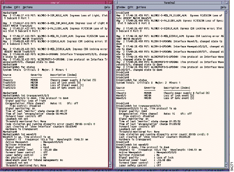
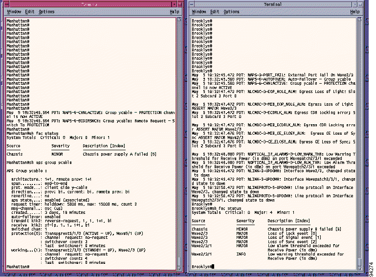
Figure 4 shows the console messages and alarms during the failure. The first message on the Manhattan console is Ingress Loss of Light, which indicates that the problem is on the client side of the transponder module in slot 5, subcard 0. The console on the Brooklyn system shows that Egress FC/ESCON loss of sync occurred on wave interface 5/0, which again points the problem in the direction of the Manhattan system. Also, the show facility-alarm status command output shows MAJOR alarms (loss of signal, loss of lock, and loss of sync) on Manhattan transparent interface 5/0/0 and MAJOR alarms (loss of lock and loss of sync) on Brooklyn wave interface 5/0. Use the show interfaces command to display the status of both Manhattan transparent interface 5/0/0 and Brooklyn wave interface 5/0.
The show facility-status alarm command output shows three MAJOR alarms. All are the result of a Rx failure on transparent interface 5/0/0. These alarms are posted from different entities in the system, as follows:
These alarms are independent of each other. However, depending on the nature of the failure, you might see one or more of these alarms. In this particular example, Rx light is lost, which means that there is no data to lock or sync. That is the reason for all three alarms. In some types of failures, loss of lock, loss of sync, or both are posted.
The symptoms observed in this example were loss of signal and loss of light. This condition can be caused by one of the following conditions.
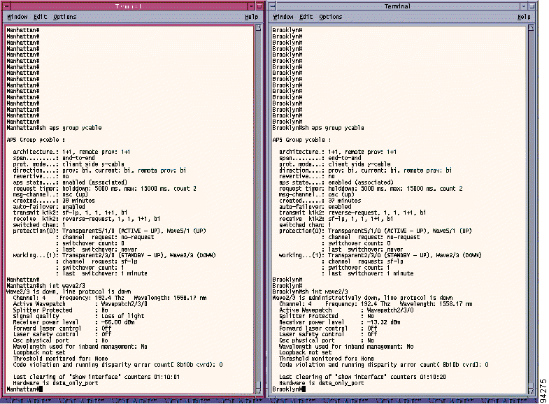
In this example, the link errors were caused by disconnecting the client Rx fiber cable from the Manhattan transparent interface 5/0/0.
In this example scenario, a loss of signal failure occurs on the wave interface on the Brooklyn system. The wave interface is on the trunk side of the transponder module. Figure 5 shows the location of the failure in the example network.
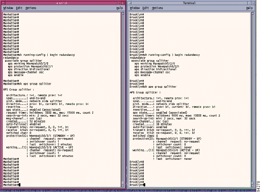
Figure 6 shows the interface, alarm, and y-cable APS status before the failure.
|
Note Ignore the MINOR alarm that indicates that the shelf does not have a redundant power supply. |
Figure 7 and Figure 8 show the messages displayed after the failure. Note that there is Egress loss of light on wave interface 2/3 that in turn triggers the APS to switch over to standby transparent interface 5/1/0.
The symptoms observed in this example were loss of signal and loss of light.These problems can be caused by one of the following conditions:
In this example, the link errors were caused by disconnecting the patch cable between the mux/demux module and the patch panel on transmit side of the Manhattan system.
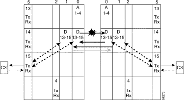
In this example the failure occurs on the SONET OC-48 channel, which is configured for splitter protection. Figure 9 shows where the failure occurred.
Figure 10 and Figure 11 show the interface, alarm, and splitter APS status before the failure occurred.
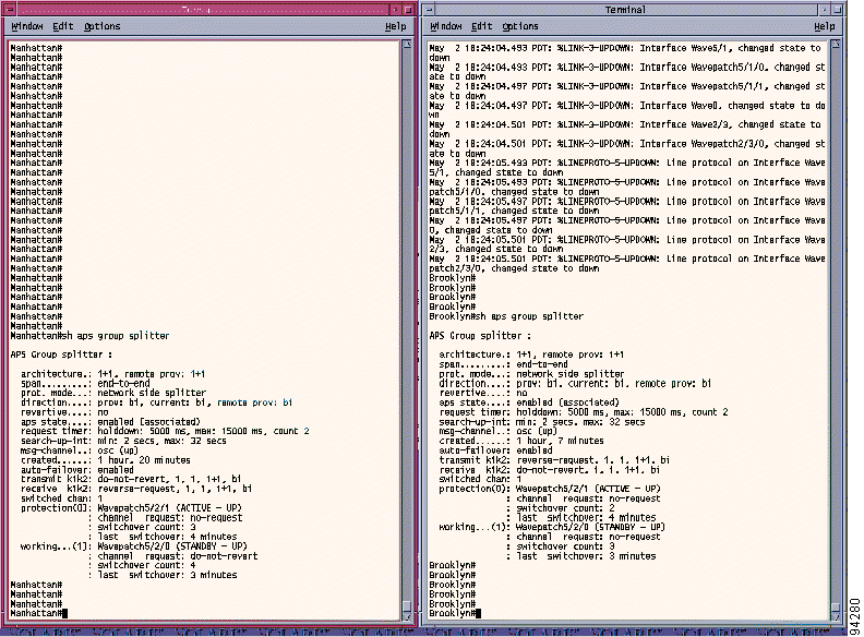
Figure 12 and Figure 13 show all the messages generated during the failure. All three channels are down because of trunk failure (common to all channels). The only indication on the Manhattan system is messages generated for the APS switchovers.
The symptoms observed were loss of signal and loss of light. This condition can be caused by one of the following conditions:
In this example, the link errors are caused by disconnecting the trunk Rx fiber cable (connected to the TRUNK_IN port on the mux/demux module in slot 0, subcard 0) of the Brooklyn system.
Cisco ONS 15540 ESPx software error messages are separated according to the facility codes shown in Table 1.
%APS-1-NO_ACTIVE: No Active Port In Group [chars]
Explanation After an active interface failure, the system switches over to the standby interface if y-cable APS was enabled. This message is posted if after a switchover the system finds that both the working and protection interfaces are not operational.
Recommended Action Isolate the cause of the failure on both the working and protection interfaces.
%APS-2-CHNLMISMATCH: Group [chars]: Channel Mismatch - In Effect

%APS-2-CHNLMISMATCH: Group [chars]: Channel Mismatch - Cleared
Explanation The received bridged channel number (in the REVERSE-REQUEST from the remote network element) does not match the request channel number in the APS request sent by the local network element. This message is relevant only for bidirectional operation.
For 1+1 APS, this message should not be posted unless the transmit bridged channel number in the REVERSE-REQUEST from remote network element is somehow corrupted, or there is a problem in the APS software itself.
Recommended Action Check for any failures on the APS communication channel. If APS communication channel is operational, contact Cisco TAC.
%APS-2-FEPF: Group [chars]: Far End Prot Failure - In Effect

%APS-2-FEPF: Group [chars]: Far End Prot Failure - Cleared
Explanation The local network element detects a Far End Protection Failure condition if the Far End Protection Defect count exceeds a threshold. The local network element detects a Far End Protection Defect when it receives a remote APS message with the request set to SF (signal failure) and the request channel set to 0 (null or protection channel).
Recommended Action Isolate the cause of the failure on the protection channel on the remote network element.
%APS-2-MODEMISMATCH: Group [chars]: Mode Mismatch - In Effect

%APS-2-MODEMISMATCH: Group [chars]: Mode Mismatch - Cleared
Explanation The local APS group was configured for bidirectional operation but the associated remote APS group was configured for unidirectional operation. A mismatch in the path switching mode (unidirectional or bidirectional) was detected.
Recommended Action Configure the remote APS group for bidirectional operation or remove bidirectional configuration on local node if unidirectional is needed.
%APS-2-NOSOCKET: Failed To Open Socket
Explanation The APS subsystem fails to create a UDP socket for exchanging APS channel protocol messages over APS message channel configured for IP. This usually is due to a low memory condition in the system.
Recommended Action Check that the NME interface is up and no collision is detected on the NME interface. A collision causes the system to use up the small NME buffer pool. Isolate the collision problem first. Reduce other system activity to ease memory demands. If the problem persists, upgrade to a larger memory configuration.
%APS-2-PSBF: Group [chars]: Prot Switch Byte Failure - In Effect

%APS-2-PSBF: Group [chars]: Prot Switch Byte Failure - Cleared
Explanation The local network element detected a Protection Switch Byte Failure when the Protection Switch Byte Defect count exceeded a threshold. The local network element detects Protection Switch Byte Defect one of the following occurs:
1. The remote APS request is not one of the supported requests.
2. The remote APS request channel number is invalid. For 1+1 APS, the channel number must be 0 or 1.
3. Operation is bidirectional and neither the local nor the remote network element is sending a REVERSE-REQUEST, and the remote APS request is of lower priority than the local APS request.
4. Operation is bidirectional and the sequence number in the remote APS REVERSE-REQUEST does not match the sequence number of the most recent APS request sent by the local network element.
This error message is posted if one of the following occurs:
1. The APS request is corrupted.
2. There is a bug in the APS software.
3. The APS communication between two network elements is not operating correctly. For example, the local network element can send and receive, but the remote network element can send but not receive.
Recommended Action Check for failures on the APS communication channel (OSC, IP, or in-band message channel).
%APS-3-PORT_FAIL: External Port Fail On [char]
Explanation The y-cable APS subsystem received a port fail indication from the driver subsystem. The specified interface has detected a failure condition (for example, loss of light).
Recommended Action Isolate the cause of the failure and restore the interface to its normal operational condition.
%APS-6-ADJUSTMODE: Group [chars]: Mode Mismatch - switching to UNI
Explanation The local APS group was configured for bidirectional operation but the associated remote APS group was configured for unidirectional operation. The local network element detected the mismatch and changed the operation to unidirectional.
Recommended Action This message is informational only.
%APS-6-ADJUSTMODE: Group [chars]: Mode Mismatch - Cleared, Restore BI
Explanation The local APS group was configured for bidirectional operation but the associated remote APS group was configured for unidirectional operation. The local network element detected the mismatch and changed the operation to unidirectional then changed back to bidirectional when the mismatch was cleared.
Recommended Action This message is informational only.
%APS-6-AUTOFOVER: Auto-Failover - Group [chars]
Explanation The APS hardware successfully switched over to the standby interface after the failure of the active interface.
Recommended Action This message is informational only.
%APS-6-BIDIRSWCH: Group [chars]: Remote Request - Switch to WORKING

%APS-6-BIDIRSWCH: Group [chars]: Remote Request - Switch to PROTECTION
Explanation An APS switchover was triggered by an APS request from the remote network element.
Recommended Action This message is informational only.
%APS-6-CHNLACTIVE: Group [chars] - WORKING channel is now ACTIVE

%APS-6-CHNLACTIVE: Group [chars] - PROTECTION channel is now ACTIVE
Explanation A previously standby channel becomes the active channel.
Recommended Action This message is informational only.
%APS-6-ENAUTFOVR: Enable Auto-Failover On [chars]
Explanation The APS software enabled the hardware to perform APS actions for failures detected by the hardware.
Recommended Action This message is informational only and displayed only when none of the following APS conditions exist on an APS channel.
%CI-1-CRITICAL_TEMP: Alarm: ASSERT, CRITICAL, Chassis, Chassis temp > critical
limit
Explanation The inlet temperature is greater than or equal to 176°F (80°C) or the outlet temperature is greater than or equal to 194°F (90°C).
Recommended Action Reduce the chassis temperature immediately by checking for the following: blocked air intake, fan tray failure, abnormal ambient environmental conditions, temperature sensor failures, and system hardware failures. One or more of these conditions probably exists. Use the show temperature command to determine the current temperatures, the thresholds, and the number and type of alarms raised.
%CI-1-FAN_MISSING: Alarm: ASSERT, CRITICAL, Chassis, Chassis fan tray missing
Explanation The system does not detect the presence of a fan tray.
Recommended Action The chassis fan tray is not installed or fails. Check the fan tray module.
%CI-1-TOTAL_BLOWER_FAIL: Alarm: ASSERT, MAJOR, Chassis, two or more fans failed
Explanation Two or more of the fans in the chassis fan tray have failed.
Recommended Action Check the fan tray module.
%CI-3-MAJOR_TEMP: Alarm: ASSERT, MAJOR, Chassis, Chassis temp > major limit
Explanation The inlet temperature is greater than or equal to 167°F (75°C) or the outlet temperature is greater than or equal to 185°F (85°C).
Recommended Action Reduce the chassis temperature by checking for the following: blocked air intake, fan tray failure, abnormal ambient environmental conditions, temperature sensor failures, and system hardware failures. One or more of these conditions probably exists. One or more of these conditions probably exists. Use the show temperature command to determine the current temperatures, the thresholds, and the number and type of alarms raised
%CI-3-MAJOR_TEMP_LOW: Alarm: ASSERT, MAJOR, Chassis, Chassis temp less than -15 C
Explanation The chassis inlet or outlet temperature is less than 5°F (-15°C).
Recommended Action Increase the ambient environmental temperature to greater than 5°F (-15°C). One or more of these conditions probably exists. Use the show temperature command to determine the current temperatures, the thresholds, and the number and type of alarms raised
%CI-3-MINOR_TEMP: Alarm: ASSERT, MINOR, Chassis, Chassis temp > minor limit
Explanation The inlet temperature is greater than or equal to 149°F (65°C) or the outlet temperature is greater than or equal to 167°F (75°C).
Recommended Action Reduce the chassis temperature by checking for the following: blocked air intake, fan tray failure, abnormal ambient environmental conditions, temperature sensor failures, and system hardware failures. One or more of these conditions probably exists. One or more of these conditions probably exists. Use the show temperature command to determine the current temperatures, the thresholds, and the number and type of alarms raised
%CI-3-PARTIAL_FAN_FAIL: Alarm: ASSERT, MINOR, Chassis, One fan failed
Explanation One of the fans in the chassis fan tray failed.
Recommended Action Check the fan tray module.
%CI-3-PWRA_FAIL: Alarm: ASSERT, MINOR, Chassis, Chassis power supply A failed
Explanation Either power source A failed or the hardware that monitors it malfunctioned.
Recommended Action Replace, reconnect, or reinstall power source A.
%CI-3-PWRB_FAIL: Alarm: ASSERT, MINOR, Chassis, Chassis power supply B failed
Explanation Either power source B failed or the hardware that monitors it malfunctioned.
Recommended Action Replace, reconnect, or reinstall power source B.
%CI-4-MULTIPLE_FAN_FAILURE:Line cards will be shutdown in 60 seconds
Explanation Two or more fans have failed and the system will power off or reset the transponder modules in the shelf to prevent damage from overheating.
 |
Caution Do not save the startup configuration file after the line cards shutdown. This action would result in losing the previous configuration. |
Action Power cycle the chassis after the to restart after resolving the fan failure.
%CI-6-FANFAIL_SHUTDOWN:Line cards are being shutdown on fan failure.
Explanation Two or more fans have failed and the system is powering off or resetting the transponder modules in the shelf to prevent damage from overheating.
Action Power cycle the chassis to restart after resolving the fan failure.
%CPU_REDUN-2-INITSYS: CPU REDUN failed RF client registration
Explanation The processor card redundancy facility client registration failed.
Recommended Action Check for sufficient processor card memory.
%CPU_REDUN-2-INITSYS: CPU REDUN missing translation index entry
Explanation The processor card redundancy facility cannot find a translation index when synchronizing messages between system image versions.
Recommended Action Check for compatible system images on the active and standby processor cards.
%CPU_REDUN-2-INITSYS: Unable to create CPU REDUN process
Explanation The processor card cannot create the redundancy facility process.
Recommended Action Check for sufficient processor card memory.
%CPU_REDUN-3-4MSEC_DISABLED: [chars] [dec] MSGDEF_LIMIT_MEDIUM
Explanation The 4-msec timer interrupt shuts off for an extended period while the hardware watchdog is enabled.
Recommended Action If the problem persists, contact Cisco TAC with show tech, show logging, and show hardware detail command outputs.
%CPU_REDUN-3-BKPLN_IDPROM_ACCESS: Alarm: ASSERT, MAJOR, CPU slot [dec], Can't
access bkpln IDPROM
Explanation The processor card cannot access the backplane IDPROM.
Recommended Action Confirm that the processor card is fully seated into the chassis slot.
%CPU_REDUN-3-CAPAB_SIZE: Mismatch in [chars]. Active=[dec], Standby=[dec].
Explanation The standby processor card reported lower capabilities than the active processor card. See message text for the type o f limitation.
Recommended Action Check for sufficient standby processor card memory for the type of memory indicated.
%CPU_REDUN-3-CAPAB_VERS: Mismatch in [chars]. Active=[dec].[dec],
Standby=[dec].[dec]
Explanation The standby processor card reports lower versions than the active processor card. See message text for the type of limitation.
Recommended Action Check the standby processor card functional version numbers.
%CPU_REDUN-3-CAPABILITIES: Alarm: ASSERT, MINOR, CPU slot [dec], Standby with
lower capabilities
Explanation The capabilities reported by the standby processor card are less than the active processor card. The processor cards are conditionally redundant, which means that a switchover could result in a partial loss of system control.
Recommended Action Upgrade either the peer software version or the hardware capability as indicated by the mismatched capability in the show redundancy capability command display.
%CPU_REDUN-3-DRIVER_MISSING: Missing [chars] driver support on Standby.
Active=[dec].[dec]
Explanation The standby processor card is missing support for one of the drivers available on the active processor card. The corresponding module fails in the event of a switchover.
Recommended Action Try upgrading the software image on the standby processor card.
%CPU_REDUN-3-DRIVER_VERSIONS: Mismatch in [chars] driver versions.
Active=[dec].[dec], Standby=[dec].[dec]
Explanation The standby processor card reported lower driver versions than the active processor card. See the message text for the type of limitation.
Recommended Action Check whether the standby and active processor cards are running the same software images.
%CPU_REDUN-3-EHSA_SVCS:
Explanation An error occurred affecting processor card redundancy services.
Recommended Action If the problem persists, contact Cisco TAC with show tech, show logging, and show hardware detail command outputs.
%CPU_REDUN-3-EHSA_SVCS: cannot open standby port [chars]
Explanation The enhanced high system availability (EHSA) standby port is not opened between the processor cards.
Recommended Action Check for sufficient processor card memory.
%CPU_REDUN-3-EHSA_SVCS: Can't communicate config register to Standby.
Explanation The configuration registers cannot be copied to the standby processor card.
Recommended Action Confirm that interprocess communications (IPC) is up.
%CPU_REDUN-3-EHSA_SVCS: Can't open slave port for EHSA msgtype [chars]
Explanation The connection between processor cards cannot transfer a specific enhanced high system availability (EHSA) message.
Recommended Action Check for sufficient processor card memory.
%CPU_REDUN-3-EHSA_SVCS: cant_send_bootvar
Explanation The bootvar (boot variable) cannot be copied between processor cards.
Recommended Action Confirm that interprocess communications (IPC) is up.
%CPU_REDUN-3-EHSA_SVCS: Didn't receive response for EHSA msgtype [chars]
Explanation The active processor card could not receive a response for an enhanced high system availability (EHSA) message from the standby processor card because of broken interprocess communications.
Recommended Action Confirm that interprocess communications (IPC) is up.
%CPU_REDUN-3-EHSA_SVCS: standby CPU can not create named port [chars]
Explanation The standby processor card cannot configure a specific port.
Recommended Action Check for sufficient processor card memory.
%CPU_REDUN-3-EHSA_SVCS: standby CPU can not register named port [chars]
Explanation The standby processor card cannot register a specific port.
Recommended Action Confirm that interprocess communications (IPC) is up.
%CPU_REDUN-3-EHSA_SVCS: Standby CPU can't allocate response for msgtype [chars]
Explanation The standby processor card cannot create a response to a specific enhanced high system availability (EHSA) message.
Recommended Action Check for sufficient processor card memory.
%CPU_REDUN-3-EHSA_SVCS: standby CPU can't register with IPC port mgr for [chars]
Explanation The standby processor card cannot register a specific port manager.
Recommended Action Confirm that interprocess communications (IPC) is up.
%CPU_REDUN-3-EHSA_SVCS: Unable to create time sync process
Explanation The time enhanced high system availability (EHSA) synchronization process is not created between processor cards.
Recommended Action Check for sufficient processor card memory.
%CPU_REDUN-3-GT_STATUS_REG: Parity Error on PCI Bus from PCI Device
Explanation The processor card system controller (GT) receives the parity error from one of the PCI device such as the PC Card, Fastethernet (NME, BPE), and SRC FPGA.
Recommended Action If the problem persists, contact Cisco TAC with show tech, show logging and show gt comman d outputs
%CPU_REDUN-3-INCONSISTENT_STATES: Alarm: ASSERT, MAJOR, CPU slot [dec],
Inconsistent redun states
Explanation The processor card redundancy state is either not consistent with the state or the software state is not consistent with the hardware state.
Recommended Action Confirm both processor cards are fully seated into the chassis slots. If the problem persists, contact Cisco TAC with show tech, show logging, and show hardware detail command outputs.
%CPU_REDUN-3-INIT_ERROR: Could not create peer cpu idb 0 0
Explanation The processor card cannot create an interface data block for the interprocess communications interface.
Recommended Action Check for sufficient processor card memory.
%CPU_REDUN-3-INIT_ERROR: Couldn't create master control port 0 0
Explanation The processor card cannot create a master control port.
Recommended Action Check for sufficient processor card memory.
%CPU_REDUN-3-INIT_ERROR: Delayed IPC registration didn't succeed 0 0
Explanation The processor card cannot queue a request for delayed interprocess communications registration.
Recommended Action Check for sufficient processor card memory.
%CPU_REDUN-3-INIT_ERROR: MAX_CLIENTS exceeded. (Client Count, MAX_CLIENTS) =
[dec] [dec]
Explanation The processor card detects that the maximum number of client connections was exceeded.
Recommended Action Check for compatible software images on the active and standby processor cards.
%CPU_REDUN-3-INIT_ERROR: MAX_DRIVERS exceeded. (Driver Count, MAX_DRIVERS) =
[dec] [dec]
Explanation The processor card detects that the maximum number of controller drivers was exceeded.
Recommended Action Check for compatible software images on the active and standby processor cards.
%CPU_REDUN-3-INIT_ERROR: metopt_get_peer_client_version (ClientID,
MAX_CLIENT_ID) = [dec] [dec]
Explanation Processor card redundancy arbitration of the client processor card image versions fails.
Recommended Action Check for compatible software images on the active and standby processor cards.
%CPU_REDUN-3-INIT_ERROR: metopt_init_local_version table init error by
ClientID=[dec] [dec]
Explanation Processor card redundancy encounters a client ID error in the local version table.
Recommended Action Contact Cisco TAC with show tech, show logging, and show hardware detail command outputs.
%CPU_REDUN-3-INIT_ERROR: metopt_init_vers_translation table init error by
ClientID= [dec] [dec]
Explanation The processor card redundancy facility encounters a client ID error in the translation table.
Recommended Action Contact Cisco TAC with show tech, show logging, and show hardware detail command outputs.
%CPU_REDUN-3-INIT_ERROR: Unable to read backplane IDPROM 0, 0
Explanation The processor card cannot read the IDPROM on the backplane.
Recommended Action Check that the processor card is fully seated in the chassis slot.
%CPU_REDUN-3-INTRPT_HOG: [chars] [dec] sec, [chars] = [hex], MSGDEF_LIMIT_SLOW
Explanation The processor card redundancy process does not run for a long period of time because an interrupt routine runs too long.
Recommended Action If the problem persists, contact Cisco TAC with show tech, show logging, and show hardware detail command outputs.
%CPU_REDUN-3-INVALID_CPU_STATES: Detected invalid redundancy states, local =
[chars], peer = [chars]
Explanation The processor card detects an invalid combination of redundant states.
Recommended Action Check that both processor cards are firmly seated in their chassis slots. If so, contact Cisco TAC with show tech, show logging, and show hardware detail command outputs.
%CPU_REDUN-3-INVALID_MSG: Incorrectly formatted message ([dec], [dec]) received
by SLO channel
Explanation An inconsistent data message is received from the peer processor card, possibly due to an incompatible image version.
Recommended Action Contact Cisco TAC with show tech, show logging, and show hardware detail command outputs.
%CPU_REDUN-3-LOCK_ERR: Can't get Global Lock
Explanation The peer processor card is not relinquishing the arbitration lock.
Recommended Action Check that both the local and peer processor cards are fully seated in the backplane. Check the status of the peer processor card.
%CPU_REDUN-3-MULTI_CARD_ACCESS: Alarm: ASSERT, MAJOR, CPU slot [dec], Can't
access multiple linecards
Explanation The processor card failed the line card access test for multiple line cards.
Recommended Action Verify that the processor card can access the line cards. If so, replace the failed processor card.
%CPU_REDUN-3-PCI_TEST: Alarm: ASSERT, MAJOR, CPU slot [dec], PCI diag failure
Explanation The processor card failed the online diagnostic internal PCI bus test.
Recommended Action Replace the processor card.
%CPU_REDUN-3-PCMCIA_TEST: Alarm: ASSERT, MINOR, CPU slot [dec], PCMCIA diag
failure
Explanation The processor card failed the online diagnostic internal PC card slot test.
Recommended Action Replace the processor card.
%CPU_REDUN-3-PEER_COMM: Alarm: ASSERT, MINOR, CPU slot [dec], Unprotected. Peer
not responding
Explanation The peer processor card is present but not responding or sending keepalives.
Recommended Action If this condition persists, check the status of the standby processor card. This alarm is suppressed by changing the redundancy configuration to maintenance mode.
%CPU_REDUN-3-PEER_MISSING: Alarm: ASSERT, MINOR, CPU slot [dec], Unprotected.
Peer missing
Explanation The peer processor card is either missing or cannot be detected. The active processor card is currently not protected.
Recommended Action Insert a compatible processor card into the standby peer chassis slot. You can suppress this alarm by changing the redundancy configuration to maintenance mode.
%CPU_REDUN-3-PEER_SEVERITY_ERR: Invalid peer CPU severity ([dec]) (current peer
register=[hex])
Explanation The peer processor card reports an invalid severity value.
Recommended Action Reseat the peer processor card. Use the show redundancy command to verify that the same system image version is running on both the active and standby processor cards.
%CPU_REDUN-3-PEER_SRC_REGS: Alarm: ASSERT, MAJOR, CPU slot [dec], Read invalid
SRC regs from peer
Explanation The active processor card detects bad parity on the active/standby status bits read from the standby processor card.
Recommended Action Reseat the peer processor card. If the problem persists, replace the peer processor card.
%CPU_REDUN-3-PEER_STATE_ERR: Invalid peer CPU state ([chars]) (current peer
register=[hex])
Explanation The peer processor card reports an invalid redundancy state. The valid states are active, standby, or non-participant.
Recommended Action Reseat the peer processor card. If the problem persists, replace the peer processor card.
%CPU_REDUN-3-RCSF: Unable to sync running config to standby
Explanation The active processor card cannot send the running configuration file to standby processor card.
Recommended Action Confirm that interprocess communications (IPC) is up.
%CPU_REDUN-3-RCSF_FAIL:Attempt to sync running config to standby failed
Explanation The running configuration file changed but was not successfully synchronized with the standby processor card.
Recommended Action Confirm that interprocess communications (IPC) is up.
%CPU_REDUN-3-READBACK_ERR: Can't change my state. desired state [chars],
read-back [chars]
Explanation The local processor card cannot set its redundancy state to the desired calculated value.
Recommended Action If accompanied by a LOCK_ERR, disregard. Otherwise, reseat the processor card. If the problem persists, contact Cisco TAC with show tech, show logging, and show hardware detail command outputs.
%CPU_REDUN-3-SLOT_IDPROM_MISMATCH: Alarm: ASSERT, MAJOR, CPU slot [dec],
IDPROM/bkpln slot mismatch
Explanation The slot ID read from the backplane IDPROM does not match the slot ID read from the processor card.
Recommended Action Confirm that the processor card is fully seated into the chassis slot. If so, confirm that the backplane IDPROM slot IDs are consistent with the actual slot position.
%CPU_REDUN-3-SRC_TEST: Alarm: ASSERT, MAJOR, CPU slot [dec], SRC diag failure
Explanation The processor card failed the online diagnostic internal SRC test.
Recommended Action Replace the processor card.
%CPU_REDUN-3-STARTUP_SYNC_FAIL:Attempt to sync startup config to standby failed
Explanation The startup configuration file changed but was not successfully synchronized with the standby processor card.
Recommended Action Check that communications are up on the standby processor card.
%CPU_REDUN-3-STARTUP_SYNC_FAIL: Attempt to sync [chars] config to standby failed
Explanation The active processor card cannot send the startup or private configuration file to the standby processor card.
Recommended Action If the problem persists, contact Cisco TAC with show tech, show logging, and show hardware detail command outputs.
%CPU_REDUN-3-SUBSYS_COMPAT: [chars] [chars] software subsystem. Active=[dec],
Standby=[dec]
Explanation A specific software subsystem is not compatible with the active and standby image versions.
Recommended Action The standby processor card software subsystem is old or missing. See message text for software subsystem type.There might be feature losses in the event of a switchover.
%CPU_REDUN-3-SW_STATE_MISMATCH: Software state ([chars]) doesn't reflect local
hardware ([chars])
Explanation The software state is not following the underlying hardware redundancy state.
Recommended Action Confirm that the processor card is firmly seated in the chassis. If so, contact Cisco TAC with show tech, show logging, and show hardware detail command outputs.
%CPU_REDUN-3-UNKNOWN_COMMON: Alarm: ASSERT, MINOR, CPU slot [dec], Unknown alarm
(metro family)
Explanation When asserted for the standby processor card, it has a different system image from the active processor card. It indicates that there is an alarm condition on the standby processor card that the active processor card cannot decode. If asserted for the active processor card, it indicates a software error condition.
Recommended Action If asserted for the standby processor card, check the status of the standby processor card and use the show logging command on the standby console connection to search for any error messages indicating an alarm condition. If asserted for the active processor card, contact Cisco TAC with show tech, show logging, and show hardware detail command outputs.
%CPU_REDUN-3-UNKNOWN_MSG: Unknown message type [chars] received by Sby EHSA svc
Explanation An unknown message type is received from the peer processor card, possibly due to an incompatible image version.
Recommended Action Check the status and configuration of the standby processor card.
%CPU_REDUN-3-UNKNOWN_MSG: Unknown message type [chars] received by SLO channel
Explanation An unknown message type is received from the peer processor card, possibly due to an incompatible image version.
Recommended Action Check the status and configuration of the standby processor card.
%CPU_REDUN-3-UNKNOWN_MSG: Unknown message type [chars] received by Standby CPU
Explanation An unknown message type is received from the peer processor card, possibly due to an incompatible image version.
Recommended Action Check the status and configuration of the standby processor card.
%CPU_REDUN-3-UNKNOWN_MSG: Unknown message type [hex] received by Active CPU
Explanation An unknown message type is received from the peer processor card, possibly due to an incompatible image version.
Recommended Action Check the status and configuration of the standby processor card.
%CPU_REDUN-3-UNKNOWN_PLAT: Alarm: ASSERT, MINOR, CPU slot [dec], Unknown alarm
(platform-specific)
Explanation When asserted for the standby processor card, it has a different system image from the active processor card. It indicates that there is an alarm condition on the standby processor card that the active processor card cannot decode. If asserted for the active processor card, it indicates a software error condition.
Recommended Action If asserted for the standby processor card, check the status of the standby processor card and use the show logging command on the standby processor card console connection to search for any error messages indicating an alarm condition. If asserted for the active processor card, contact Cisco TAC with show tech, show logging, and show hardware detail command outputs.
%CPU_REDUN-4-REPROGRAM_ACTIVE_CPU: Active CPU FPGA has been reprogrammed. Please
remove and re-insert the CPU in slot <slot> or power-cycle the box, for the new
FPGA to take effect.
Explanation The active processor card functional image has been reprogrammed and further action is required for it to take effect.
Recommended Action If possible make the processor card in the numbered slot the standby processor card, then remove and reinsert it. Alternatively, save the configuration and power-cycle the entire box if a data outage is tolerable.
%CPU_REDUN-4-STARTUP_CONFIG_MISSING: Non-volatile configuration memory is not
present
Explanation The startup configuration is missing. This may be because of a manual user erase command or an interrupted write to the startup configuration.
Recommended Action Perform a copy running-config startup-config to save the current system configuration. If the problem persists, contact Cisco TAC with show tech, show logging, and show hardware detail command ouptuts.
%CPU_REDUN-4-UNPROTECTED: Peer CPU hasn't reached Hot Standby after [dec]
minutes.
Explanation The system is running for an extended period in an unprotected mode even though a peer processor card is present.
Recommended Action Check whether the standby processor card booted the system image. If the standby processor card is not responsive, reseat the card and try again. If the problem persists, replace the peer processor card.
%CPU_REDUN-5-BASIC_CAPABILITY: Peer CPU hardware and software is fully
compatible.
Explanation The standby processor card, drivers, and software subsystems have matching versions and capabilities.
Recommended Action This message is informational only.
%CPU_REDUN-5-EHSA_SVCS_RESP: Sending [chars] = [dec], 30*ONESEC
Explanation A normal EHSA redundancy service response is sent by the processor card.
Recommended Action This message is informational only.
%CPU_REDUN-5-FORCE_CLOSE: Forcibly closing fd: [dec] name:[chars]
Explanation A file activity timeout occurred on the standby processor card.
Recommended Action If the problem persists, contact Cisco TAC with show tech, show logging, and show hardware detail command outputs.
%CPU_REDUN-5-NEGOTIATED_SWITCHOVER: Reloading due to negotiated switchover, sev
= [dec]
Explanation A switchover occurred due to a change in either the severity or state of one of the processor cards as a result of either a hardware or software fault.
Recommended Action Check the status of the new standby processor card and replace it if it is faulty.
%CPU_REDUN-5-PEER_EXITED_IOS:Peer CPU has exited IOS
Explanation The peer processor card exited Cisco IOS and temporarily returned to ROM monitor mode. This might indicate either a user-initiated reload or a software crash.
Recommended Action If the peer processor card rebooted, issue a show stacks command to verify if a crash stack trace was recorded. Check the show version command output to verify the reported reason for return to ROM monitor mode. If a software crash occurred, contact Cisco TAC with the crash information.
%CPU_REDUN-5-PEER_REMOVED:Peer CPU has been removed from the chassis
Explanation The peer processor card was either partially or fully removed from the chassis.
Recommended Action If the peer processor card is still physically present in the chassis, verify that both processor cards are fully seated in their slots.
%CPU_REDUN-5-RCSF_SYNCED:Running config successfully synced to standby
Explanation The running configuration file successfully synchronized with the standby processor card.
Recommended Action This message is informational only.
%CPU_REDUN-5-RELOAD_COMM_DOWN: Reloading standby since Active CPU shows loss of
comm.
Explanation A reload of the standby processor card occurred because the active processor card reported that communications to the standby processor card were down.
Recommended Action Check that the standby processor card is firmly seated in the chassis slot. If it is, check that communications are up between the processor cards.
%CPU_REDUN-5-STARTUP_CONFIG_SYNCED:Startup config successfully synced to standby
Explanation The startup configuration file successfully synchronized with the standby processor card.
Recommended Action This message is informational only.
%CPU_REDUN-5-STATE_MISMATCH_RELOAD: Reloading due to a hardware software state
mismatch.
Explanation A reload occurred because the software state is not consistent with the processor card hardware state as a result of either a hardware or software fault (IPC down).
Recommended Action Check the status of the processor card that issued the error message. Replace the processor card if it is faulty.
%CPU_REDUN-5-STATUS_CHG; A CPU hardware redundancy status change occurred.
Explanation A processor redundancy switchover recently took place.
Recommended Action Check the reason for the processor redundancy switchover. If it was due to activeUnitFailed, check the status of the peer processor card hardware. If the problem persists, contact Cisco TAC with show tech, show logging, and show hardware detail command outputs.
%CPU_REDUN-5-SWITCHOVER:Switchover occurred. Reason:[chars]
Explanation A processor redundancy switchover recently took place.
Recommended Action Check the reason for the processor redundancy switchover. If it was due to activeUnitFailed, check the status of the peer processor card hardware.
%CPU_REDUN-5-UNSUPPORTED_MSG: Msgtype [chars] sent by [chars] unsupported by
peer. MSGDEF_LIMIT_SLOW
Explanation The peer processor card does not recognize messages sent by the local processor card possibly due to a different image version. This can also happen if the message is corrupted in transit from the active to the standby processor card.
Recommended Action Upgrade the software image on the standby processor card. If the problem persists, contact Cisco TAC with show tech, show logging, and show hardware detail command ouputs.
%CPU_REDUN-5-UNSUPPORTED_MSG: Msgtype SLAVE_SERVICES_SETTIME_REQ sent by EHSA
svcs uncsupported by peer.
Explanation Redundancy Set Time message updates occur every minute. This error is likely due to a corrupted message or a busy peer CPU that failed to handle the message during one of those minutes. The time will synchronize the next minute unless there is another error message.
Recommended Action This message in informational only.
%CPU_REDUN-6-BOOTED_AS_ACTIVE:After returning to ROM by [chars]
Explanation This processor card initially came up as active and no switchovers have occurred.
Recommended Action This message is informational only.
%CPU_REDUN-6-EHSA_SVCS_EVENT: %s %s", 30*ONESEC
Explanation A significant EHSA redundancy service event occurred.
Recommended Action This message is informational only.
%CPU_REDUN-6-RUNNING_CONFIG_CHG:Running config on this CPU has possibly changed
Explanation The running configuration file might have changed as a result of a global configuration command entered from the CLI.
Recommended Action This message is informational only.
%CPU_REDUN-6-STARTUP_CONFIG_CHG:Startup config on this CPU has possibly changed
Explanation The startup configuration file might have changed as a result of a user configuration command.
Recommended Action This message is informational only.
%FILESYS-4-RCSF: running config Too big to sync.. [dec]
Explanation The file system detects the running configuration file is too large to synchronize with the standby processor card.
Recommended Action Check for sufficient processor card memory.
%FILESYS-4-RCSF: Secondary running config close failed [chars] [chars]
Explanation The file system tries to close the standby processor card running configuration file and the process fails.
Recommended Action Contact Cisco TAC with show tech, show logging, and show hardware detail command outputs.
%FILESYS-4-RCSF: Secondary running config is not opened [chars]
Explanation The standby processor card running configuration file is not opened.
Recommended Action Contact Cisco TAC with show tech, show logging, and show hardware detail command outputs.
%FILESYS-4-RCSF: Secondary running config open failed [chars] [chars]
Explanation The file system tries to open the standby processor card running configuration file and the process fails.
Recommended Action Confirm that interprocess communications (IPC) is up.
%FILESYS-4-RCSF: Secondary running config write error [chars] [chars]
Explanation The file system tries to write the standby processor card running configuration file and the process fails.
Recommended Action Confirm that interprocess communications (IPC) is up. Use the redundancy manual-sync running-config command to attempt setting the configuration again.
%FILESYS-4-RCSF: Secondary running config write incomplete [chars]
Explanation The file system tries to write the standby processor card running configuration file and the process fails before completion.
Recommended Action Confirm that interprocess communications (IPC) is up. Use the redundancy manual-sync running-config command to attempt setting the configuration again.
%IPC-2-CANT_SEND: Cannot send IPC message: [chars]
Explanation There is an error in the IPC standby discovery mechanism. It might result in a malfunction in the operation of the IPC.
Recommended Action Something is seriously wrong. Examine the traceback for clues. Contact Cisco TAC with show tech, show logging, and show hardware detail command outputs.
%IPC-2-INVALSIZE: IPC message received with invalid size(size/type - [dec]/[dec])
Explanation An IPC message is received with an invalid size and is probably corrupted.
Recommended Action Check the traceback for the failed component. Contact Cisco TAC with show tech, show logging, and show hardware detail command outputs.
%IPC-2-LOCK: Lock done a deleted element
Explanation An internal inconsistency was found in some IPC data structures.
Recommended Action Something is seriously wrong. Examine the traceback for clues. Contact Cisco TAC with show tech, show logging, and show hardware detail command outputs.
%IPC-2-NODISPATCH: Message for [dec].[dec] has no receive queue or dispatch
routine
Explanation An IPC caller fails to provide any means of handling a received message.
Recommended Action Someone created an IPC port with no handler for it. Use the output of the show ipc ports command to try to determine who created the port. Contact Cisco TAC with show tech, show logging, and show hardware detail command outputs.
%IPC-2-NOMEM: No memory available for Deferred-close Ports
Explanation The IPC protocol subsystem cannot obtain the memory it needs.
Recommended Action There is not enough memory to initialize the required data structures needed by the IPC. This message should appear only when the system is booting. If the IPC cannot initialize, add more memory to the system.
%IPC-2-NOMEM: No memory available for failed to create [dec] messages
Explanation The IPC protocol subsystem cannot obtain the memory it needs.
Recommended Action There is not enough memory to initialize the required data structures needed by the IPC. This message should appear only when the system is booting. If the IPC cannot initialize, add more memory to the system.
%IPC-2-NOMEM: No memory available for getbuffer fails
Explanation The IPC protocol subsystem cannot obtain the memory it needs.
Recommended Action There is not enough memory to initialize the required data structures needed by the IPC. This message should appear only when the system is booting. If the IPC cannot initialize, add more memory to the system.
%IPC-2-NOMEM: No memory available for IPC system initialization
Explanation The IPC protocol subsystem cannot obtain the memory it needs.
Recommended Action There is not enough memory to initialize the required data structures needed by the IPC. This message should appear only when the system is booting. If the IPC cannot initialize, add more memory to the system.
%IPC-2-ONINT: Called from interrupt level: ipc_close_ports_on_seat()
Explanation The IPC user issues a prohibited call into the IPC while the IPC is running on the interrupt stack.
Recommended Action Look at the traceback and the output of the show ipc status command to try to determine the cause of the problem. Contact Cisco TAC with show tech, show logging, and show hardware detail command outputs.
%IPC-2-ONINT: Called from interrupt level: ipc_remove_port()
Explanation The IPC user issues a prohibited call into the IPC while the IPC is running on the interrupt stack.
Recommended Action Look at the traceback and the output of the show ipc status command to try to determine the cause of the problem. Contact Cisco TAC with show tech, show logging, and show hardware detail command outputs.
%IPC-2-ONINT: Called from interrupt level: ipc_remove_ports_on_seat()
Explanation The IPC user issues a prohibited call into the IPC while the IPC is running on the interrupt stack.
Recommended Action Look at the traceback and the output of the show ipc status command to try to determine the cause of the problem. Contact Cisco TAC with show tech, show logging, and show hardware detail command outputs.
%IPC-2-PRECLOSE: IPC port pre-closure overflow : [dec] : [dec]
Explanation An application attempts to close an IPC port when there are messages pending in the retransmit queue and the IPC defer table overflows.
Recommended Action Look at the traceback and the output of the show ipc ports command to try to determine the application that caused the problem. Contact Cisco TAC with show tech, show logging, and show hardware detail command outputs.
%IPC-2-UNLOCK: Unlock done on already unlocked element
Explanation An internal inconsistency is found in some IPC data structures.
Recommended Action Something is seriously wrong. Examine the traceback for clues. Contact Cisco TAC with show tech, show logging, and show hardware detail command outputs.
%IPC-3-DELETED: Attempt to delete an IPC message ([hex]) a second time
Explanation An internal inconsistency is found in some IPC data structures.
Recommended Action An IPC message was freed twice. Look at the traceback and the output of the show ipc status and show ipc queue commands to try to determine the cause of the problem. Contact Cisco TAC with show tech, show logging, and show hardware detail command outputs.
%IPC-3-GIANT: Request for giant IPC packet denied. Request size = [dec]
Explanation An IPC user requests a message that is too large for the IPC system.
Recommended Action Check the traceback for the source of the request.
%IPC-3-LOWBUFF: The main IPC message header cache below application reserve count
([dec]).
Explanation The main IPC message header cache falls below the application reserve count.
Recommended Action Check for sufficient processor card memory.
%IPC-3-NOBUFF: The [chars] IPC message header cache has emptied
Explanation The given IPC message header cache is empty.
Recommended Action Check for sufficient processor card memory.
%IPC-4-CONSISTENCY: Message failed consistency check: ipc_fragment_first: message
already has fragment.
Explanation An IPC message is received with an invalid size and is probably corrupted.
Recommended Action Check the traceback for the source of the problem. Contact Cisco TAC with show tech, show logging, and show hardware detail command outputs.
%IPC-4-CONSISTENCY: Message failed consistency check: ipc_remove_port: missing
name.
Explanation An internal inconsistency is found in some IPC data structures. An IPC caller probably passed on bad information.
Recommended Action Check the traceback for the source of the problem. Contact Cisco TAC with show tech, show logging, and show hardware detail command outputs.
%IPC-4-CONSISTENCY: Message failed consistency check: message data_buffer & data
== NULL
Explanation An internal inconsistency is found in some IPC data structures. An IPC caller probably passed on bad information.
Recommended Action Check the traceback for the source of the problem. Contact Cisco TAC with show tech, show logging, and show hardware detail command outputs.
%IPC-4-CONSISTENCY: Message failed consistency check: send_message: dest port
send vector is NULL.
Explanation An internal inconsistency was found in some IPC data structures. An IPC caller probably passed on bad information.
Recommended Action Check the traceback for the source of the problem. Contact Cisco TAC with show tech, show logging, and show hardware detail command outputs.
%IPC-4-CONSISTENCY: Message failed consistency check: send_message: input IPC
dest port info is NULL.
Explanation An internal inconsistency was found in some IPC data structures. An IPC caller probably passed on bad information.
Recommended Action Check the traceback for the source of the problem. Contact Cisco TAC with show tech, show logging, and show hardware detail command outputs.
%IPC-4-CONSISTENCY: Message failed consistency check: send_message: input IPC
message is NULL.
Explanation An internal inconsistency was found in some IPC data structures. An IPC caller probably passed on bad information.
Recommended Action Check the traceback for the source of the problem. Contact Cisco TAC with show tech, show logging, and show hardware detail command outputs.
%IPC-4-GET_PAK_MSG: Failed for message size=[dec]
Explanation The system is out of packet type buffers of required size.
Recommended Action It could be either transient, which might require an image with reconfigured packet type buffers, or permanent, which could be a memory leak (check the traceback). Contact Cisco TAC with show tech, show logging, and show hardware detail command outputs.
%LCMDC-3-ACCESS_FAIL: Alarm: ASSERT, MAJOR, MuxDemuxMB [dec], Access to LRC
failed
Explanation The online diagnostics cannot access the line card redundancy controller on the mux/demux motherboard without OSC.
Recommended Action Reseat the line card motherboard. If the problem persists, replace the line card motherboard.
%LCMDC-3-ACCESS_FAIL: Alarm: ASSERT, MAJOR, MuxDmuxOSCMB [dec], Access to LRC
failed
Explanation The online diagnostics cannot access the line card redundancy controller (LRC) from the mux/demux motherboard with OSC.
Recommended Action Reseat the mux/demux motherboard. If the problem persists, replace the mux/demux motherboard.
%LCMDC-3-ACCESS_FAIL: Alarm: ASSERT, MAJOR, TranspdrMB [dec], Access to LRC
failed
Explanation The online diagnostics cannot access the line card redundancy controller (LRC) on the line card motherboard.
Recommended Action Reseat the line card motherboard. If the problem persists, replace the line card motherboard.
%LCMDC-3-ACCESS_FAIL: Alarm: ASSERT, MAJOR, TranspdrSC [dec]/[dec], Access to
Tspcard failed
Explanation The online diagnostics cannot access the transponder module.
Recommended Action Reseat the transponder module and try again. If the problem persists, replace the transponder module or the line card motherboard.
%LCMDC-3-CDL_HEC_ETX_ALM: CDL HEC Err count; Slot [dec] Subcard [dec] Port [dec]
Explanation A transponder module generates a converged data link header error control error when it exceeds the HEC error failure threshold.
Recommended Action Check for high or low power levels. Also check for and clean dirty optical patch cable connectors.
%LCMDC-3-CDL_RFOF_IND: CDL Drop FIFO OvrFL; Slot [dec] Subcard [dec] Port [dec]
Explanation A transponder module generates a converged data link drop first-in first-out error.
Recommended Action Check the network connection.
%LCMDC-3-ECDRLK_ALM : Egress CDR Locking error; Slot [dec] Subcard [dec] Port
[dec]
Explanation The monitoring on a transponder module reports a loss of lock.
Recommended Action Check the connecting cable and laser power levels. Check configured encapsulation or clock rate.
%LCMDC-3-EOP_NOLG_ALM: Egress Loss of Light; Slot [dec] Subcard [dec] Port [dec]
Explanation The received power level on the trunk drops below the low alarm threshold or a loss of light condition occurs on the trunk.
Recommended Action Check for broken or dirty trunk Rx fiber cable. Excessive attenuation on the trunk can also cause this error condition. It is also likely that the transponder module transmitter on the remote end is bad or the optical patch cable connecting the mux/demux module to the line card motherboard is bad or the transponder module receiver is faulty.
%LCMDC-3-EOP_NOLG_PALM: Egress Loss of Light Prealarm: Slot [dec] Subcard [dec]
Port [dec]
Explanation A transponder module generates a loss of light pre-alarm error on an egress connection.
Recommended Action Check for broken or dirty trunk Rx fiber cable. Excessive attenuation on the trunk can also cause this error condition. It is also likely that the transponder module transmitter on the remote end is bad or the optical patch cable connecting the mux/demux module to the line card motherboard is bad or the transponder module receiver is faulty.
%LCMDC-3-EOP_TKSW_ALM: Egress Trunk Switch Mech. Failure; Slot [dec] Subcard
[dec] Port [dec]
Explanation A line card motherboard generates a mechanical error on an egress connection.
Recommended Action Reseat the line card motherboard and test the optical switch. If the problem persists, replace the line card motherboard.
%LCMDC-3-FH_ECETX_ALM: Egress Fiber Channel/ESCON Line Err; Slot [dec] Subcard
[dec] Port [dec]
Explanation A transponder module generates a Fibre Channel or ESCON line error on an egress connection.
Recommended Action Check the trunk power level for high or low conditions that can cause this error. Adjust the attenuation as needed. Also check for dirty cables or connectors and clean them.
%LCMDC-3-FH_ELOSY_ALM: Egress FC/ESCON Loss of Sync; Slot [dec] Subcard [dec] Port
[dec]
Explanation A transponder module generates a Fibre Channel or ESCON loss of synchronization error on an egress connection.
Recommended Action Check for high or low optical power levels, broken cable, and dirty connectors or cable on the trunk side.
%LCMDC-3-FH_ILOSY_ALM: Ingress FC/ESCON Loss of Sync; Slot [dec] Subcard [dec]
Port [dec]
Explanation A transponder module generates a Fibre Channel or ESCON loss of synchronization error on an ingress connection.
Recommended Action Check for high or low optical power levels, broken cable, and dirty connectors or cable on the trunk side.
%LCMDC-3-GE_ECETX_ALM: Egress GE Line Code Err count; Slot [dec] Subcard [dec]Port
[dec]
Explanation A transponder module Gigabit Ethernet line code error count exceeds the maximum setting on an egress connection.
Recommended Action Check the optical fiber patch between the mux/demux modules or the cable on the client side.
%LCMDC-3-GE_ELOSY_ALM: Egress GE Loss of Sync; Slot [dec] Subcard [dec] Port [dec]
Explanation A transponder module generates a Gigabit Ethernet loss of synchronization error on an egress connection.
Recommended Action Check for high or low optical power levels, broken cable, and dirty connectors or cable on the trunk side.
%LCMDC-3-GE_ILOSY_ALM: Ingress GE Loss of Sync; Slot [dec] Subcard [dec] Port
[dec]
Explanation A transponder module generates a Gigabit Ethernet loss of synchronization error on an ingress connection.
Recommended Action Check for high or low optical power levels, broken cable, and dirty connectors or cable on the trunk side.
%LCMDC-3-GE_LOSY_ALM : GE Loss of Sync; Slot [dec] Subcard [dec] Port [dec]
Explanation The monitoring on a transponder module reports loss of synchronicity.
Recommended Action Check for high or low optical power levels, broken cable, and dirty connectors or cable on the trunk side.
%LCMDC-3-GH_ICETX_ALM: Ingress GE Line Code Err; Slot [dec] Subcard [dec] Port
[dec]
Explanation The Gigabit Ethernet line code error count on a transponder module exceeds the maximum setting on an ingress connection.
Recommended Action Check the optical fiber patch between the mux/demux modules or the cable on the client side.
%LCMDC-3-ICDRLK_ALM : Ingress CDR Locking error; Slot [dec] Subcard [dec] Port
[dec]
Explanation The CDR (clock and data recovery unit) on a transponder module cannot lock to incoming signal on the client side.
Recommended Action Check for high or low optical power levels, broken cables, and dirty connectors or cables on the client side. Check configured encapsulation or clock rate.
%LCMDC-3-IDPROM_ACCESS_FAIL: Alarm: ASSERT, MINOR, MuxDemuxMB [dec], Access to
IDPROM failed
Explanation The online diagnostics cannot access the IDPROM on a mux/demux motherboard with OSC.
Recommended Action Reseat the mux/demux motherboard. If the problem persists, replace the mux/demux motherboard.
%LCMDC-3-IDPROM_ACCESS_FAIL: Alarm: ASSERT, MINOR, MuxDmuxOSCMB [dec], Access to
IDPROM failed
Explanation The online diagnostics cannot access the IDPROM on a mux/demux motherboard with OSC.
Recommended Action Reseat the mux/demux motherboard. If the problem persists, replace the mux/demux motherboard.
%LCMDC-3-IDPROM_ACCESS_FAIL: Alarm: ASSERT, MINOR, TranspdrMB [dec], Access to
IDPROM failed
Explanation The online diagnostics cannot access the IDPROM on a line card motherboard.
Recommended Action Reseat the line card motherboard. If the problem persists, replace the line card motherboard.
%LCMDC-3-IDPROM_ACCESS_FAIL: Alarm: ASSERT, MINOR, TranspdrSC [dec]/[dec], Access
to IDPROM  failed
Explanation The online diagnostics cannot access the IDPROM on a transponder module.
Recommended Action Reseat the transponder module. If the problem persists, replace the transponder module.
%LCMDC-3-IOP_NOLG_ALM Ingress Loss of Light; Slot [dec] Subcard [dec] Port [dec]
Explanation A transponder module generates a loss of light error on an ingress connection.
Recommended Action Check for high or low optical power levels, broken cables, and dirty connectors or cables on the client side.
%LCMDC-3-LINE_LASER_FAIL: Alarm: ASSERT, MAJOR, TranspdrSC [dec]/[dec], Line
laser failure detected
Explanation The client side laser failed.
Recommended Action Replace the transponder module or SFP optics.
%LCMDC-3-LN_OFC_IND: Line OFC IND; Slot [dec] Subcard [dec] Port [dec]
Explanation A transponder module generates an open fiber control (OFC) indication error.
Recommended Action Check the connecting cables or connectors.
%LCMDC-3-LN_TX_ALM: Line Laser Failure; Slot [dec] Subcard [dec] Port [dec]
Explanation A transponder module generates a client side laser error.
Recommended Action Replace the transponder module or SFP optics.
%LCMDC-3-MDSUBCARD_IDPROM_FAIL: Alarm: ASSERT, MINOR, MuxDemuxSC [dec]/[dec],
Access to IDPROM failed
Explanation The online diagnostics cannot read the IDPROM on a mux/demux module.
Recommended Action Reseat the mux/demux module. If the problem persists, replace the mux/demux module.
%LCMDC-3-OPT_SWITCH_0_FAIL: Alarm: ASSERT, MAJOR, TranspdrMB[dec], Waveport 0 opt
switch failed
Explanation The system associated with wave port 0 fails.
Recommended Action Reseat the line card motherboard and test the optical switch. If the problem persists, replace the line card motherboard.
%LCMDC-3-OPT_SWITCH_1_FAIL: Alarm: ASSERT, MAJOR, TranspdrMB[dec], Waveport 1 opt
switch failed
Explanation The system associated with wave port 1 fails.
Recommended Action Reseat the line card motherboard and test the optical switch. If the problem persists, replace the line card motherboard.
%LCMDC-3-OSC_HW_FAIL: Alarm: ASSERT, MAJOR, MuxDmuxOSCMB [dec], OSC hardware
failure detected
Explanation The online diagnostics detects an OSC hardware failure (loopback and monitoring access).
Recommended Action Reseat the mux/demux motherboard. If the problem persists, replace the mux/demux motherboard.
%LCMDC-3-SH_BIP_ETX_ALM : SONET BIP Err count; Slot [dec] Subcard [dec] Port [dec]
Explanation The performance monitor on a transponder module reports bit interleave parity (BIP) error rate exceeds failure threshold.
Recommended Action Check the optical fiber patch between the mux/demux modules or the cable on the client side. Also check that the power levels are too high or too low.
%LCMDC-3-SH_EBIP_ALM: Egress SONET BIP Err count; Slot [dec] Subcard [dec] Port
[dec]
Explanation A transponder module generates a SONET bit interleave parity (BIP) error on an egress connection.
Recommended Action Check the optical fiber patch between the mux/demux modules or the cable on the client side. Also check that the power levels are too high or too low.
%LCMDC-3-SH_ELOF_ALM: Egress SONET Loss of Frame; Slot [dec] Subcard [dec] Port
[dec]
Explanation A transponder module generates a SONET loss of frame (LOF) error on an egress connection.
Recommended Action Check the power level for too high or too low conditions. Apply the appropriate attenuation. Also check for dirty cables or connectors and clean them.
%LCMDC-3-SH_ESEF_ALM: Egress SONET SEF; Slot [dec] Subcard [dec] Port [dec]
Explanation A transponder module generates a SONET severely errored frame (SEF) error on an egress connection.
Recommended Action Check the power level for too high or too low conditions. Apply the appropriate attenuation. Also check for dirty cables or connectors and clean them.
%LCMDC-3-SH_IBIP_ALM: Ingress SONET BIP error; Slot [dec] Subcard [dec] Port [dec]
Explanation A transponder module generates a SONET bit interleave parity (BIP) error on an ingress connection.
Recommended Action Check the optical fiber patches between the mux/demux modules or the cable on the client side. Check the power level for too high or too low conditions. Adjust the attenuation if necessary. Also check for dirty cables or connectors and clean them.
%LCMDC-3-SH_ILOF_ALM: Ingress SONET Loss of Frame; Slot [dec] Subcard [dec] Port
[dec]
Explanation A transponder module generates a SONET loss of frame (LOF) error on an ingress connection.
Recommended Action Check for high/low optical power levels, broken cables, and dirty connectors or cables on the client side.
%LCMDC-3-SH_ISEF_ALM: Ingress SONET SEF; Slot [dec] Subcard [dec] Port [dec]
Explanation A transponder module generates a SONET severely errored frame (SEF) error on an ingress connection.
Recommended Action Check for high/low optical power levels, broken cables, and dirty connectors or cables on the client side.
%LCMDC-3-SH_LOF_ALM : SONET Loss of Frame; Slot [dec] Subcard [dec] Port [dec]
Explanation The performance monitor on a transponder module reports a loss of frame (LOF); an auto-failover will be attempted to correct it.
Recommended Action Check the transponder module or line card motherboard specific to slot/subslot.
%LCMDC-3-TK_TX_ALM Transmit Failure; Slot [dec] Subcard [dec] Port [dec]
Explanation A transponder module generates a transmit failure error.
Recommended Action Replace the transponder module or line card motherboard.
%LCMDC-3-TRUNK_LASER_DEGRADE: Alarm: ASSERT, MAJOR, MuxDmuxOSCMB [dec], Trunk
laser degrade detected
Explanation The multiprotocol monitor in the OSC reports a trunk laser degrade monitor alarm or general transmit circuit fault.
Recommended Action If the problem persists when the OSC wave interface is up, replace the mux/demux motherboard with OSC.
%LCMDC-3-TRUNK_LASER_DEGRADE: Alarm: ASSERT, MAJOR, TranspdrSC [dec]/[dec], Trunk
laser degrade detected
Explanation The multiprotocol monitor in the transponder module reports a trunk laser degrade monitor alarm or general transmit circuit fault.
Recommended Action If the problem persists when the transponder module interfaces are up, replace the transponder module.
%LCMDC-3-TRUNK_LASER_DEVIATION: Alarm: ASSERT, MAJOR, MuxDmuxOSCMB [dec], Trunk
laser lambda deviation
Explanation The multiprotocol monitor in the OSC reports a trunk laser wavelength deviation alarm.
Recommended Action If the problem persists when the OSC wave interface is up, replace the mux/demux motherboard with OSC.
%LCMDC-3-TRUNK_LASER_DEVIATION: Alarm: ASSERT, MAJOR, TranspdrSC [dec]/[dec],
Trunk laser lambda deviation
Explanation The multiprotocol monitor in transponder module reports trunk laser wavelength deviation alarm.
Recommended Action If the problem persists when the transponder module interfaces are up, replace the transponder module.
%LCMDC-3-WAVELENGTH_MISMATCH: Alarm: ASSERT, MAJOR, TranspdrSC [dec]/[dec],
Wavelength mismatch error
Explanation The wavelength from a wave port on the transponder module is not the same as the filter port.
Recommended Action Confirm that the transponder module is installed in the correct channel slot and that the line card motherboard is patched to the correct mux/demux module.
%LCMDC-4-SH_BIP_ETX_ALM : SONET BIP Err count; Slot [dec] Subcard [dec] Port [dec]
Explanation The performance monitor on a transponder module reports bit interleave parity (BIP) error rate exceeds degrade threshold.
Recommended Action Check the optical fiber patch between the mux/demux modules or the cable on the client side.
%LCMDC-4-SH_ESEF_ALM : Egress SONET SEF
Explanation The performance monitor on a transponder module reports severely errored frames (SEF).
Recommended Action Check for high or low optical power level, broken cables, and dirty connectors or cables.
%LCMDC-4-SH_LOF_ALM : SONET Loss of Frame; Slot [dec] Subcard [dec] Port [dec]
Explanation The performance monitor on a transponder module reports a loss of frame (LOF).
Recommended Action Check for high or low optical power level, broken cables, and dirty connectors or cables on the client side.
%LCMDC-6-SH_ESEF_ALM : Egress SONET SEF
Explanation The performance monitor on a transponder module reports severely errored frames (SEF).
Recommended Action Check for high or low optical power level, broken cables, and dirty connectors or cables.
%METOPT_DRV-2-NOMEMORY: No memory available for Notification Process
Explanation There is no memory to create the notification process, which handles port alarms and port fail interrupts. This is a very critical error.
Recommended Action Copy the error message exactly as it appears on the console or in the system log, and report it to Cisco technical support.
%METOPT_DRV-2-NOMEMORY: No memory available for OIR process
Explanation There is no memory for the creation of the OIR process. Online insertion and removal does not work without this process.
Recommended Action Copy the error message exactly as it appears on the console or in the system log, and report it to Cisco technical support.
%METOPT_DRV-2-NOMEMORY: No memory available for SRC Standby To Active Process
Explanation There is no memory to create the SRC standby-to-active process, which handles SRC driver actions during a switchover. The system cannot function correctly without this process.
Recommended Action Copy the error message exactly as it appears on the console or in the system log, and report it to Cisco technical support.
%METOPT_DRV-2-PORTFAIL: Port Fail event received Slot [dec] Subcard [dec] Port
[dec]; HWIDB, [chars]
Explanation A port has failed.
Recommended Action Check the trunk and client side connections.
%METOPT_DRV-2-ZEROLEN_MSG: Zero length while writing to linecard. Datalen [dec]
Explanation A zero length message is received while writing to a module.
Recommended Action Copy the error message exactly as it appears on the console or in the system log, and report it to Cisco technical support.
%METOPT_DRV-3-IDPROM_MISMATCH: Mismatch in backplane IDPROM, [chars]:
Active-side=[chars], Sby-side=[chars]
Explanation The backplane contains two IDPROMs that should be programmed with identical values for most fields, but mismatch on the current backplane.
Recommended Action Report the error message text to Cisco technical support.
%METOPT_DRV-3-IDPROM_MISMATCH: Mismatch in backplane IDPROM, lengths:
Active-side=[dec], Sby-side=[dec]
Explanation A hardware version mismatch occurs on the backplane IDPROM.
Recommended Action Confirm that the compatibility of the processor card hardware and image versions.
%METOPT_DRV-3-IDPROM_STR_MISMATCH: Mismatch in backplane IDPROM, [chars],
Active-side=[chars] Sby-side=[chars]
Explanation An IDPROM string mismatch occurs on the backplane IDPROM.
Recommended Action Replace the transponder module.
%METOPT_DRV-3-IDPROM_STR_MISMATCH: Mismatch in backplane IDPROM, initialization,
Active-side=[chars/chars] Sby-side=[chars/chars]
Explanation An IDPROM string mismatch occurs during initialization on the backplane IDPROM.
Recommended Action Replace the transponder module.
%METOPT_DRV-3-REPROGRAM_ERROR
Explanation The reprogramming of the functional image fails and does not identify the nature of the problem.
Recommended Action Reprogram the card again. If the problem persists, remove and reinsert the card. If the problem still persists, save the console log and contact Cisco technical support.
%METOPT_DRV-3-TP_INTERNAL_ERROR:[chars]
Explanation The transponder driver subsystem encountered an internal software error.
Recommended Action Ensure that the card present and that the interface exists in the system.
%METOPT_DRV-3-UNEXP_INTR: [chars]
Explanation This problem should be self-correcting but indicates either a hardware or a software defect. If it is a hardware defect, further problems are to be expected. If it is a software problem, certain types of error and alarm conditions might be left undetected.
Recommended Action Copy the error message exactly as it appears, and report it to Cisco technical support.
%METOPT_DRV-6-AUTOFAILOVER: Failover Event received Slot [dec] Subcard [dec] Port
[dec]
Explanation One of the branches of the splitter failed to receive light and the hardware switched over to the other branch.
Recommended Action Check the trunk side connections for kinks or a fiber cut.
%ODM-3-CPU_TEST_FAIL:CPU card, [chars] Failed
Explanation The online diagnostic test failed for this processor card.
Recommended Action Remove and reinsert the processor card. If the problem persists, then replace the processor card.
%ODM-3-DIAG_DISABLE:Online Diags disabled for all slots without specific config
Explanation The online diagnostic tests were disabled for all slots except those with specific configurations.
Recommended Action The message is informational only.
%ODM-3-DIAG_ENABLE:Online Diags enabled for all slots without specific config
Explanation The online diagnostic tests were enabled for all slots except those with specific configurations.
Recommended Action The message is informational only.
%ODM-3-LC_TEST_FAIL:Slot [dec] [chars] Failed
Explanation The online diagnostic test failed for the line card.
Recommended Action Check the line card seating and LEDs. Remove and reinsert the line card. If the problem persists, replace the line card.
%ODM-3-PEER_INCOMPATIBLE:Online Diags Peer Version is different
Explanation The version of the peer online diagnostics manager is different.
Recommended Action The message is informational only.
%ODM-3-SC_TEST_FAIL:Slot [dec], Subcard [dec], [chars] Failed
Explanation The online diagnostic test failed for a module.
Recommended Action Check the line card seating and LEDs. If the problem persists, remove and reinsert the motherboard. If the problem still persists, replace the module.
%OIR-3-BADFPGAIMG: Controller in in slot [dec] does not have a valid FPGA image
Explanation A line card is inserted online and the line card is not able to verify that the functional image is valid.
Recommended Action Reseat the line card. If the problem persists, replace the line card.
%OIR-3-BADIDPROM: IDPROM in slot [dec] not properly programmed
Explanation The line card is inserted and the IDPROM on the line card is not accessible.
Recommended Action Reseat the line card. If the problem persists, replace the line card.
%OIR-3-LINE_CARD_NOT_READY: Line card in slot [dec] not becoming ready after OIR
Explanation The module inserted in the slot (shown in the message) is not becoming ready for access. This can apply to mux/demux modules or any other module inserted in a specific slot.
Recommended Action Reseat the module. If the problem persists, replace the module.
%OIR-3-RF_REGISTRTN_FAILED: OIR Client failed to register with RF
Explanation The OIR process failed to register with the RF (redundancy facility) and redundancy might not be available.
Recommended Action Copy the error message exactly as it appears on the console or in the system log, and report it to Cisco technical support.
%OIR-3-SUBCARD_SCAN_ERR: Error in scanning subcards in slot [dec]
Explanation The module inserted in the slot (given in the message) is not becoming ready for access. This can apply to mux/demux modules or any other module inserted in a specific slot.
Recommended Action Copy the error message exactly as it appears on the console or in the system log, and report it to Cisco technical support.
%OIR-6-DETECT: Detected Mux Demux card in slot [dec]
Explanation A mux/demux module is inserted into the slot.
Recommended Action This message is informational only.
%OIR-6-DETECT: Detected CPU card in slot [dec]
Explanation A processor card is inserted into the slot.
Recommended Action This message is informational only.
%OIR-6-DETECT: Detected Transponder card in slot [dec]
Explanation A 2.5-Gbps transponder module is inserted into the slot.
Recommended Action This message is informational only.
%OIR-6-DETECT: Detected Unknown card in slot [dec]
Explanation An unknown card type is inserted into the slot. This card will not work properly.
Recommended Action Try removing the card and inserting it again. If the problem persists, copy the message exactly as it appears and contact Cisco technical support.
%OIR-6-REMOVE: Removed Mux Demux card in slot [dec]
Explanation A mux/demux module was removed from the slot.
Recommended Action This message is informational only.
%OIR-6-REMOVE: Removed CPU card in slot [dec]
Explanation A processor card was removed from the slot.
Recommended Action This message is informational only.
%OIR-6-REMOVE: Removed Transponder card in slot [dec]
Explanation A 2.5-Gbps transponder module was removed from the slot.
Recommended Action This message is informational only.
%OIR-6-REMOVE: Removed Unknown card in slot [dec]
Explanation An unknown card type was removed from the slot.
Recommended Action Try reinserting the card and removing it again. If the problem persists, copy the message exactly as it appears and contact Cisco technical support.
%OIR-6-SUBCARD_DEACT: Slot [dec]: [LC [dec]] subcards deactivated
Explanation A 2.5-Gbps line card motherboard was removed from the slot.
Recommended Action This message is informational only.
%OIR-6-SUBCARD_DEACT: Slot [dec]: [MDC [dec]] subcards deactivated
Explanation A mux/demux module was removed from the slot.
Recommended Action This message is informational only.
%OIR-6-SUBCARD_DISC: Slot [dec]: [MDC [dec]] subcards discovery
Explanation A mux/demux module is inserted into the slot.
Recommended Action This message is informational only.
%OIR-6-SUBCARD_DISC: Slot [dec]: [LC [dec]] subcards discovery
Explanation A 2.5-Gbps transponder module is inserted into the slot.
Recommended Action This message is informational only.
%OIR-6-SUBCARDDETECT: Slot [dec] LC [dec]: subcard [dec] inserted
Explanation A 2.5-Gbps transponder module is inserted into the slot.
Recommended Action This message is informational only.
%OIR-6-SUBCARDDETECT: Slot [dec] MDC [dec]: subcard [dec] inserted
Explanation A mux/demux module is inserted into the slot.
Recommended Action This message is informational only.
%OIR-6-SUBCARDREMOVE: Slot [dec] LC [dec]: subcard [dec] removed
Explanation A 2.5-Gbps transponder module was removed from the slot.
Recommended Action This message is informational only.
%OIR-6-SUBCARDREMOVE: Slot [dec] MDC [dec]: subcard [dec] removed
Explanation A mux/demux module was removed from the slot.
Recommended Action This message is informational only.
%OPTICAL_IF-1-ALARM : Transparent[dec]/[dec]/[dec], [chars]: Signal degrade
threshold cleared
Explanation A specific threshold degrade alarm for a transparent interface was cleared.
Recommended Action Check the source of the alarm.
%OPTICAL_IF-1-ALARM : Transparent[dec]/[dec]/[dec], [chars]: Signal degrade
threshold exceeded
Explanation A specific threshold degrade alarm for a transparent interface was exceeded.
Recommended Action Check the source of the alarm.
%OPTICAL_IF-1-ALARM : Transparent[dec]/[dec]/[dec], [chars]: Signal failure
threshold cleared
Explanation A specific threshold failure alarm for a transparent interface was cleared.
Recommended Action Check the source of the alarm.
%OPTICAL_IF-1-ALARM : Transparent[dec]/[dec]/[dec], [chars]: Signal failure
threshold exceeded
Explanation A specific threshold failure alarm for a transparent interface was exceeded.
Recommended Action Check the source of the alarm.
%OPTICAL_IF-1-ALARM : Wave[dec]/[dec], [chars]: Signal degrade threshold cleared
Explanation A specific threshold degrade alarm for a wave interface was cleared.
Recommended Action Check the source of the alarm.
%OPTICAL_IF-1-ALARM : Wave[dec]/[dec], [chars]: Signal degrade threshold exceeded
Explanation A specific threshold degrade alarm for a wave interface was exceeded.
Recommended Action Check the source of the alarm.
%OPTICAL_IF-1-ALARM : Wave[dec]/[dec], [chars]: Signal failure threshold cleared
Explanation A specific threshold failure alarm for a wave interface was cleared.
Recommended Action Check the source of the alarm.
%OPTICAL_IF-1-ALARM : Wave[dec]/[dec], [chars]: Signal failure threshold exceeded
Explanation A specific threshold failure alarm for a wave interface was exceeded.
Recommended Action Check the source of the alarm.
%OPTICAL_IF-1-INTERNAL_ERROR : [chars]
Explanation The metopt subsystem encounters an internal software error. Use the error message text to identify the problem.
Recommended Action Check the source of the alarm.
%OSCP-3-INTERNAL_ERROR: Cannot add Optical interface [dec]
Explanation A processor card cannot add a specific optical interface number.
Recommended Action Check the status or configuration of the specific optical interface.
%OSCP-3-INTERNAL_ERROR: Cannot add OSCP interface [dec]
Explanation The processor card cannot add the OSC interface wave 0 or 1.
Recommended Action Check the status or the configuration of the OSC interface.
%OSCP-3-INTERNAL_ERROR: group id out of bounds [chars]
Explanation A group ID is configured out of bounds of the group.
Recommended Action Check the configuration of the OSCP neighbor node IP address and peer group name.
%OSCP-3-INTERNAL_ERROR: Hello state machine error in state [chars], event [chars]
port [dec]
Explanation The OSCP receives a Hello state error.
Recommended Action Check the status of the transmitting node.
%OSCP-3-INTERNAL_ERROR: OSCP failed to get the argument to oscp_hello process,
pid = [dec]
Explanation The OSCP fails to get an argument for the OSCP Hello process and displays its PID (process identifier).
Recommended Action Contact Cisco TAC with show tech, show logging, and show hardware detail command outputs.
%OSCP-3-INTERNAL_ERROR: OSCP failed to set the argument to oscp hello process,
pid = [dec]
Explanation The OSCP fails to set an argument to the OSCP Hello process and displays the PID group messages.
Recommended Action Check the OSCP configuration of the Hello interval and hold-down timers.
%OSCP-3-INTERNAL_ERROR: Received API message to create an interface for an
existing port [dec]
Explanation An API (application programmable interface) tries to create an interface where one already exists.
Recommended Action Check the configuration and status of the NMS application and the interface being configured.
%OSCP-3-INTERNAL_ERROR: Received unrecognized API message [chars]
Explanation An unrecognized API message is received.
Recommended Action Check the configuration of the NMS applications and the connecting interface.
%OSCP-4-BADPACKET: Invalid pkt: length shorter than header size [dec].
Explanation An invalid packet is received from a network peer.
Recommended Action Check the originating device for a cause of the corrupted packets.
%RF-1-SYSTEM_INTEGRITY: Automatic switch of activity occurred while the CPUs were
in maintenance mode
Explanation An automatic switch of activity occurs when the processor card is disabled.
Recommended Action Check the status of the active and standby processor cards and the configuration of the disabling application.
%RF-3-COMMUNICATION: Communication with the peer CPU has been established
Explanation Communication with the peer processor card is established.
Recommended Action The message is informational only.
%RF-3-COMMUNICATION: Communication with the peer CPU has been lost
Explanation The interprocess communication was lost to the peer processor card. This could indicate that the processor card is not currently fully operational, or that there is a hardware problem in one of the processor cards.
Recommended Action Check the status of the peer processor card. Check that both processor cards are firmly seated in the chassis.
%RF-3-IPC_PORT: Unable to create [chars] [chars]
Explanation The processor card cannot create a configuration for an interface.
Recommended Action Check for sufficient processor card memory.
%RF-3-IPC_PORT: Unable to open [chars] [chars]
Explanation The processor card cannot open an interface.
Recommended Action Check for sufficient processor card memory.
%RF-3-IPC_PORT: Unable to register [chars] [chars]
Explanation The processor card cannot register the configuration for an interface.
Recommended Action Check for sufficient processor card memory.
%RF-3-SIMPLEX_MODE: The peer CPU has been lost
Explanation The absence of the peer processor card was detected.
Recommended Action Check the status of the standby processor card. It could have failed.
%RF-3-STANDBY_RELOAD: The standby CPU is being reset because [chars] took too long
processing a progression event
Explanation The peer processor card was reset. This allows recovery from an indeterminate standby state.
Recommended Action Confirm that interprocess communications (IPC) is up.
%RF-3-STANDBY_RELOAD: The standby CPU is being reset because keepalive message(s)
not received from peer CPU
Explanation The standby processor card is reset because keepalive messages are not being received from the active processor card.
Recommended Action Check the status of the active processor card and the communication between the active and standby processor cards.
%RF-3-STANDBY_RELOAD: The standby CPU is being reset because the peer CPU failed
during progression
Explanation The error occurs for the reason reported in the error message. This allows recovery from an indeterminate standby state.
Recommended Action Confirm that interprocess communications (IPC) is up.
%RF-3-SYSTEM_INTEGRITY: Automatic switch of activity occurred while an
application had disabled it
Explanation An automatic switch of activity occurred when redundancy synchronization was disabled.
Recommended Action Contact Cisco TAC with show tech, show logging, and show hardware detail command outputs.
%SRC-3-LC_REG_READ_FAIL: Register read failed for slot
[dec], addr [hex], with failcode as [hex]
Explanation The SRC cannot read the line card register.
Recommended Action Copy the error message exactly as it appears on the console or in the system log, call your Cisco technical support representative, and provide the representative with the gathered information.
%SRC-3-LC_REG_WRITE_FAIL: Register write failed for slot [dec], addr [hex], with
failcode as [hex]
Explanation The SRC cannot write the line card register.
Recommended Action Copy the error message exactly as it appears on the console or in the system log, call your Cisco technical support representative, and provide the representative with the gathered information.
%SRC-3-LC_CMI_INTF_FAULT: SRC detected a CMI interface fault for line card in slot
[dec]
Explanation The SRC detected a CMI interface fault.
Recommended Action Copy the error message exactly as it appears on the console or in the system log, call your Cisco technical support representative, and provide the representative with the gathered information.
%SRC-3-LC_APS_INTF_FAULT: SRC detected a APS interface fault for line card in slot
[dec]
Explanation The SRC detected an APS interface fault.
Recommended Action Copy the error message exactly as it appears on the console or in the system log, call your Cisco technical support representative, and provide the representative with the gathered information.
%SRC-3-LC_APS_INTF_INIT_FAULT: SRC-LRC APS interface could not be initialized for
line card in slot [dec]
Explanation The SRC unable to read the line card register.
Recommended Action Copy the error message exactly as it appears on the console or in the system log, call your Cisco technical support representative, and provide the representative with the gathered information.
%SRC-3-LC_APS_TIMEOUT: SRC detected keep alive timeout on APS intferace for
slot[dec]
Explanation The SRC unable to read the line card register.
Recommended Action Copy the error message exactly as it appears on the console or in the system log, call your Cisco Technical support representative, and provide the representative with the gathered information.
%SRC-3-LC_CMI_TIMEOUT: SRC detected keep alive timeout on CMI intferace for slot
[dec]
Explanation The SRC unable to read the line card register.
Recommended Action Copy the error message exactly as it appears on the console or in the system log, call your Cisco technical support representative, and provide the representative with the gathered information.
%SRC-3-AFOVEN_ERROR: Attempt to enable [chars] protection autofailover on
interface [chars] when port status is [hex]
Explanation Software attempt at enabling autofailover port status is does not succeed.
Recommended Action Copy the error message exactly as it appears on the console or in the system log, call your Cisco technical support representative, and provide the representative with the gathered information.
%TENGIGE_LC-3-LASER_TEMP_ERR: Laser Temperature Alarm : [dec]/[dec]
Explanation The 10-GE laser temperature exceeds the normal operating temperature.
Recommended Action Reduce the temperature immediately by checking for the following: blocked air intake, fan tray failure, abnormal ambient environmental conditions, temperature sensor failure, and 10-GE hardware failure. One or more of these conditions probably exists.
%TENGIGE_LC-3-LASER_TX_POWER_ERR: Laser did not reach the expected power level...
disabling now : [dec]/[dec]
Explanation The laser power does not reach the expected power level.
Recommended Action Reseat the 10-GE transponder module. If the problem persists, replace the module.
%TENGIGE_LC-3-XPLTA2D: Err calculating xpolated value: [chars]
Explanation The 10-GE transponder module not seated properly or the IDPROM is corrupted.
Recommended Action Reseat the 10-GE transponder module. If the problem persists, replace the module.
%TENGIGE_LC-3-INTF_CREATE_FAILED: Interface Create Failed : [chars]
Explanation The 10-GE driver subsystem cannot obtain the memory it needs to initialize its data structures. This message should only appear when this problem occurs during system booting.
Recommended Action Check for any offending processes hogging processor card memory. Add more memory to the system if needed.
%TENGIGE_LC-3-RDWRFAIL: Read/write failed: [chars]
Explanation The error occurs when 10-GE driver tries to access hardware registers.
Recommended Action Reseat the 10-GE transponder module. If the problem persists, replace the module.
%TENGIGE_LC-3-TENGIGE_RXLOP_ALM: [chars] Receive Loss Of Light: [chars]
Explanation The 10-GE receiver detects a loss of light on the client side.
Recommended Action Check for broken or dirty client Rx fiber cables. Excessive attenuation on the client side can also cause this error condition. It is also likely that 10-GE client equipment connected to the 10-GE transponder module is offline or faulty.
%TENGIGE_LC-3-TENGIGE_LSBIAS_ALM: [chars] Laser BIAS threshold exceeded alarm;
laser is starting to die; [chars]
Explanation The error occurs when 10-GE laser bias current exceeded the threshold.
Recommended Action Reseat the 10-GE transponder module and check that you have a surge-free power supply source. If the problem persists, replace the module.
%TENGIGE_LC-3-TENGIGE_LSTMP_ALM: [chars] Laser exceeded the operating temperature
threshold: [chars]
Explanation The 10-GE laser temperature exceeds the operating temperature threshold.
Recommended Action Reduce the temperature immediately by checking for the following: blocked air intake, fan tray failure, abnormal ambient environmental conditions, temperature sensor failure, and 10-GE 10-GE transponder hardware failure. One or more of these conditions probably exists.
%TENGIGE_LC-6-TENGIGE_TRUNK_RX_PALM: Trunk side Loss of Light Pre-Alarm: [chars]
Explanation The 10-GE receiver detects a loss of light or low power level below the configured low threshold on the previous active interface.
Recommended Action This message is informational only.
%TENGIGE_LC-3-TENGIGE_RXLCK_ALM: [chars] Loss of Lock on Receive: [chars]
Explanation The 10-GE CDR (clock and data recovery) unit cannot lock to incoming signal.
Recommended Action Check for dirty cables or connectors, for excessive attenuation of the signal, and that the OSNR is within the recommended level.
%TENGIGE_LC-3-TENGIGE_TRUNK_RX_LCK_PALM: Trunk side Loss of Lock Pre-Alarm:
[chars]
Explanation The 10-GE CDR (clock and data recovery) unit cannot lock to incoming trunk signal.
Recommended Action Check for dirty cables or connectors on the trunk side, for excessive attenuation of the signal, and that the OSNR is within recommended level.
%TENGIGE_LC-3-TENGIGE_OVF_ALM: [chars] Transmit to Trunk FIFO overflow: [chars]
Explanation The trunk transmit buffer overflowed.
Recommended Action This could be a temporary condition. If it persists, reseat the card and verify.
%TENGIGE_LC-3-TENGIGE_SF_ALM: Signal Failure : [chars]
Explanation The 10-GE receiver detects a loss of sync or loss of lock.
Recommended Action Check for broken or dirty Rx fiber cables or connectors. Excessive attenuation can also cause this error.
%TENGIGE_LC-6-TENGIGE_TRUNK_RX_SF_PALM: Trunk side Signal Failure Prealarm:
[chars]
Explanation The 10-GE receiver detects a loss of sync or loss of lock on the trunk Rx.
Recommended Action This message is informational only.
%TENGIGE_LC-3-TENGIGE_LOSYNC_ALM: [chars] side Loss of Sync lock: [chars]
Explanation The 10-GE protocol monitor detects a loss of sync lock.
Recommended Action Check for dirty Rx fiber cables or connectors. Check receive power levels.
%TENGIGE_LC-3-TENGIGE_TRUNK_RX_LOSYNC_PALM: Trunk side Loss of Sync lock
Prealarm: [chars]
Explanation The 10-GE protocol monitor detects a loss of sync lock pre-alarm.
Recommended Action This message is information only
%TENGIGE_LC-3-TENGIGE_CETXE: [chars] side Line Code Err count: [chars]
Explanation The 10-GE receiver detects a line code error.
Recommended Action Check for dirty Rx fiber cables or connectors. Check receive power levels.
%TENGIGE_LC-3-TENGIGE_TRUNK_CETXE_PALM: Trunk side Line Code err count: [chars]
Explanation The 10-GE transponder module detects a line code error.
Recommended Action Check for dirty Rx fiber cables or connectors. Check receive power levels.
%TENGIGE_LC-3-TENGIGE_CDL_HEC_ETX_ALM: [chars] side CDL HEC error count: [chars]
Explanation The 10-GE transponder module detects a CDL HEC error.
Recommended Action Check receive power levels. Check for dirty Rx fiber cables or connectors.
%TENGIGE_LC-3-TENGIGE_TRUNK_CDL_HETX_PALM: Trunk side CDL HEC error count:
[chars]
Explanation The 10-GE transponder module detects a CDL HEC error.
Recommended Action Check receive power levels. Check for dirty Rx fiber cables or connectors.
%TENGIGE_LC-3-TENGIGE_TRUNK_CDL_RFOF_IND: Trunk side CDL Drop FIFO OvrFL: [chars]
Explanation The trunk transmit CDL buffer overflowed.
Recommended Action This could be a temporary condition. If it persists, reseat the card and verify.
%TENGIGE_LC-6-TENGIGE_FOV_IND: Trunk Receive splitter Hardware Autofailover
occured: [chars]
Explanation A hardware switchover on the splitter occurred.
Recommended Action This message is informational only.
%TENGIGE_LC-3-TENGIGE_SW_ALM: Autofailover switch failed to switch to the other
branch: [chars]
Explanation The hardware switchover to the standby path fails. This could happen due to a bad switch on the line card motherboard.
Recommended Action Reseat the 10-Gbps line card motherboard. If the problem persists, replace the 10-Gbps line card motherboard.
%TENGIGE_LC-6-TENGIGE_RXLOP_ALM_CLR: CLEARED : [chars] Loss Of Light: [chars]
Explanation The loss of light alarm is cleared.
Recommended Action This message is informational only.
%TENGIGE_LC-6-TENGIGE_LSBIAS_ALM_CLR: CLEARED : [chars] Laser BIAS threshold
[chars]
Explanation The laser bias threshold alarm is cleared.
Recommended Action This message is informational only.
%TENGIGE_LC-6-TENGIGE_LSTMP_ALM_CLR: CLEARED : [chars] Laser temperature
threshold: [chars]
Explanation The laser temperature threshold alarm is cleared.
Recommended Action This message is informational only.
%TENGIGE_LC-6-TENGIGE_RXLCK_ALM_CLR: CLEARED : [chars] Loss of Lock on Receive:
[chars]
Explanation The loss lock alarm is cleared.
Recommended Action This message is informational only.
%TENGIGE_LC-6-TENGIGE_OVF_ALM_CLR: CLEARED : [chars] Transmit to Trunk FIFO
overflow: [chars]
Explanation The Tx trunk buffer overflow alarm is cleared.
Recommended Action This message is informational only.
%TENGIGE_LC-6-TENGIGE_SF_ALM_CLR: CLEARED : [chars] Signal Failure : [chars]
Explanation The signal failure alarm is cleared.
Recommended Action This message is informational only.
%TENGIGE_LC-6-TENGIGE_LOSYNC_ALM_CLR: CLEARED : [chars] Loss of Sync lock:
[chars]
Explanation The loss of sync alarm is cleared.
Recommended Action This message is informational only.
%TENGIGE_LC-6-TENGIGE_CETXE_CLR: CLEARED : [chars] Line code Err count: [chars]
Explanation The line code error alarm is cleared.
Recommended Action This message is informational only.
%TENGIGE_LC-6-TENGIGE_CDL_HEC_ETX_ALM_CLR: CLEARED : [chars] CDL HEC error count:
[chars]
Explanation The CDL HEC error alarm is cleared.
Recommended Action This message is informational only.
%TENGIGE_LC-6-LASER_SOFT_START: Starting the 10GE trunk laser turn on procedures
for : [dec], [dec]
Explanation The 10-GE transponder module in the process of turning on the trunk laser.
Recommended Action This message is informational only.
%TENGIGE_LC-6-LASER_TEMP_WAIT: Waiting for the laser to reach the expected
temperature level : [dec]/[dec]
Explanation The 10-GE transponder module is waiting for the laser temperature to reach its expected temperature for laser to operate normally.
Recommended Action This message is informational only.
%TENGIGE_LC-6-LASER_DISABLED: Laser disabled as per user configuration
[dec]/[dec]
Explanation Forward laser control is enabled on the 10-GE transponder module.
Recommended Action This message is informational only.
%TENGIGE_LC-6-LASER_OK: Laser on [dec]/[dec] is ready for traffic !!
Explanation The laser is turned on after initialization and is ready to receive traffic.
Recommended Action This message is informational only.
%TENGIGE_LC-6-LASER_TX_POWER_WAIT: Waiting for the 10GE laser to reach steady
power : [dec]/[dec]
Explanation 10-GE transponder module is waiting for the laser to reach steady power.
Recommended Action This message is informational only.
Cisco provides several ways to obtain documentation, technical assistance, and other technical resources. These sections explain how to obtain technical information from Cisco Systems.
You can access the most current Cisco documentation on the World Wide Web at this URL:
http://www.cisco.com/univercd/home/home.htm
You can access the Cisco website at this URL:
International Cisco websites can be accessed from this URL:
http://www.cisco.com/public/countries_languages.shtml
Cisco documentation and additional literature are available in a Cisco Documentation CD-ROM package, which may have shipped with your product. The Documentation CD-ROM is updated regularly and may be more current than printed documentation. The CD-ROM package is available as a single unit or through an annual or quarterly subscription.
Registered Cisco.com users can order a single Documentation CD-ROM (product number DOC-CONDOCCD=) through the Cisco Ordering tool:
http://www.cisco.com/en/US/partner/ordering/ordering_place_order_ordering_tool_launch.html
All users can order monthly or quarterly subscriptions through the online Subscription Store:
http://www.cisco.com/go/subscription
You can find instructions for ordering documentation at this URL:
http://www.cisco.com/univercd/cc/td/doc/es_inpck/pdi.htm
You can order Cisco documentation in these ways:
http://www.cisco.com/en/US/partner/ordering/index.shtml
You can submit comments electronically on Cisco.com. On the Cisco Documentation home page, click Feedback at the top of the page.
You can e-mail your comments to bug-doc@cisco.com.
You can submit comments by using the response card (if present) behind the front cover of your document or by writing to the following address:
Cisco Systems
Attn: Customer Document Ordering
170 West Tasman Drive
San Jose, CA 95134-9883
Cisco provides Cisco.com, which includes the Cisco Technical Assistance Center (TAC) website, as a starting point for all technical assistance. Customers and partners can obtain online documentation, troubleshooting tips, and sample configurations from the Cisco TAC website. Cisco.com registered users have complete access to the technical support resources on the Cisco TAC website, including TAC tools and utilities.
Cisco.com offers a suite of interactive, networked services that let you access Cisco information, networking solutions, services, programs, and resources at any time, from anywhere in the world.
Cisco.com provides a broad range of features and services to help you with these tasks:
To obtain customized information and service, you can self-register on Cisco.com at this URL:
http://tools.cisco.com/RPF/register/register.do
The Cisco TAC is available to all customers who need technical assistance with a Cisco product, technology, or solution. Two types of support are available: the Cisco TAC website and the Cisco TAC Escalation Center. The type of support that you choose depends on the priority of the problem and the conditions stated in service contracts, when applicable.
We categorize Cisco TAC inquiries according to urgency:
The Cisco TAC website provides online documents and tools to help troubleshoot and resolve technical issues with Cisco products and technologies. To access the Cisco TAC website, go to this URL:
All customers, partners, and resellers who have a valid Cisco service contract have complete access to the technical support resources on the Cisco TAC website. Some services on the Cisco TAC website require a Cisco.com login ID and password. If you have a valid service contract but do not have a login ID or password, go to this URL to register:
http://tools.cisco.com/RPF/register/register.do
If you are a Cisco.com registered user, and you cannot resolve your technical issues by using the Cisco TAC website, you can open a case online at this URL:
http://www.cisco.com/tac/caseopen
If you have Internet access, we recommend that you open P3 and P4 cases online so that you can fully describe the situation and attach any necessary files.
The Cisco TAC Escalation Center addresses priority level 1 or priority level 2 issues. These classifications are assigned when severe network degradation significantly impacts business operations. When you contact the TAC Escalation Center with a P1 or P2 problem, a Cisco TAC engineer automatically opens a case.
To obtain a directory of toll-free Cisco TAC telephone numbers for your country, go to this URL:
http://www.cisco.com/warp/public/687/Directory/DirTAC.shtml
Before calling, please check with your network operations center to determine the Cisco support services to which your company is entitled: for example, SMARTnet, SMARTnet Onsite, or Network Supported Accounts (NSA). When you call the center, please have available your service agreement number and your product serial number.
Information about Cisco products, technologies, and network solutions is available from various online and printed sources.
http://www.cisco.com/en/US/products/products_catalog_links_launch.html
http://www.cisco.com/go/packet
http://www.cisco.com/go/iqmagazine
http://www.cisco.com/en/US/about/ac123/ac147/about_cisco_the_internet_protocol_journal.html
http://www.cisco.com/en/US/learning/le31/learning_recommended_training_list.html
This document is to be used in conjunction with the documents listed in the "Obtaining Documentation" section.
CIP, CCSP, the Cisco Arrow logo, the Cisco Powered Network mark, Cisco Unity, Follow Me Browsing, FormShare, and StackWise are trademarks of Cisco Systems, Inc.; Changing the Way We Work, Live, Play, and Learn, and iQuick Study are service marks of Cisco Systems, Inc.; and Aironet, ASIST, BPX, Catalyst, CCDA, CCDP, CCIE, CCNA, CCNP, Cisco, the Cisco Certified Internetwork Expert logo, Cisco IOS, the Cisco IOS logo, Cisco Press, Cisco Systems, Cisco Systems Capital, the Cisco Systems logo, Empowering the Internet Generation, Enterprise/Solver, EtherChannel, EtherSwitch, Fast Step, GigaStack, Internet Quotient, IOS, IP/TV, iQ Expertise, the iQ logo, iQ Net Readiness Scorecard, LightStream, MGX, MICA, the Networkers logo, Networking Academy, Network Registrar, Packet, PIX, Post-Routing, Pre-Routing, RateMUX, Registrar, ScriptShare, SlideCast, SMARTnet, StrataView Plus, Stratm, SwitchProbe, TeleRouter, The Fastest Way to Increase Your Internet Quotient, TransPath, and VCO are registered trademarks of Cisco Systems, Inc. and/or its affiliates in the U.S. and certain other countries.
All other trademarks mentioned in this document or Web site are the property of their respective owners. The use of the word partner does not imply a partnership relationship between Cisco and any other company. (0304R)
Copyright © 2003 Cisco Systems, Inc. All rights reserved.
![]()
![]()
![]()
![]()
![]()
![]()
![]()
![]()
Posted: Thu Sep 11 14:33:46 PDT 2003
All contents are Copyright © 1992--2003 Cisco Systems, Inc. All rights reserved.
Important Notices and Privacy Statement.