|
|

Table Of Contents
Troubleshooting Network Topologies
Troubleshooting Unprotected Point-to-Point Topology
Troubleshooting Point-to-Point Topology with Splitter Protection
Troubleshooting Point-to-Point Topology with Line Card Protection
Troubleshooting Hubbed Ring Topology with Splitter Protection
Troubleshooting Hubbed Ring Topology with Line Card Protection
Troubleshooting Meshed Ring Topology with Splitter Protection
Troubleshooting Meshed Ring Topology with Line Card Protection
Troubleshooting Network Topologies
This chapter provides information on troubleshooting point-to-point, ring, and meshed ring network topologies. This chapter includes the following sections:
•
Troubleshooting Unprotected Point-to-Point Topology
•
•
•
•
•
•
Each of these topologies can be configured with or without protection. For detailed information on network topologies, refer to the Cisco ONS 15540 ESP Planning Guide and for information on how to configure these topologies, refer to the Cisco ONS 15540 ESP Configuration Guide and Command Reference.
Checking Connectivity
There are two procedures for troubleshooting connections in network topologies. The first involves checking the connectivity of the interfaces. If that fails, then the second involves running the more disruptive loopback tests.
Loopback tests are an important part of troubleshooting. They are used to isolate the fault on an end-to-end circuit (especially when the circuit is down). The loopback diagnostic command causes traffic going out of a transparent or a wave interface to come back to the system and confirms the connection.
Caution
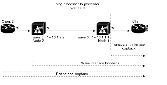
Figure 5-1 shows a simple, point-to-point topology without protection between two Cisco ONS 15540 systems, node 1 and node 2. Some steps may seem redundant but following this process in this order should help troubleshoot the connection with the least disruption to the other connections on the network.
Note
Figure 5-1 General Connection Troubleshooting Steps
To troubleshoot the configuration and status of the optical connections, use the following EXEC commands:
Follow these general steps to troubleshoot an optical fiber network connection between two end user clients:
Step 1
Node1# show interfaces transparent 2/2/0Transparent2/2/0 is up, line protocol is up
Encap: Sonet Rate: oc12Signal monitoring: onConfigured threshold Group: NoneThreshold monitored for: BIP1 errorSet threshold SF:10e-5 SD:10e-7Bip1 Count: 0Number of times SF threshold exceeded: 0Number of times SD threshold exceeded: 0Number of errored seconds: 0Number of severely errored seconds: 0Number of severely errored framing seconds: 0Number of times SEF alarm raised: 0Hardware is transparentEncapsulation UNKNOWN, loopback not setLast input never, output never, output hang neverLast clearing of "show interface" counters 04:17:45Node1#The show interfaces transparent command indicates whether the connection between the Cisco ONS 15540 and the client equipment is up. See the "Troubleshooting Client Side Transparent Interfaces" section on page 3-1 for information about the fields in this display.
Step 2
Node1# show interfaces wave 2/2Channel: 3 Frequency: 192.3 Thz Wavelength: 1558.98 nmActive Wavepatch : Wavepatch2/2/0Splitter Protected: NoReceiver power level: -15.34 dBmForward laser control: OffLaser safety control: OffOsc physical port: NoWavelength used for inband management: NoConfigured threshold Group: NoneCode violation and running disparity error count(cvrd): 0Number of times SF threshold exceeded: 0Number of times SD threshold exceeded: 0Loopback not setLast clearing of "show interface" counters 14:35:39Hardware is data_only_portNode1#The show interfaces wave command indicates whether the connection between the Cisco ONS 15540 and the next neighboring node is up. See the Chapter 4, "Troubleshooting Trunk Side Interfaces," for information about the fields in this display.
Step 3
Node1# ping 10.1.2.2Type escape sequence to abort.Sending 5, 100-byte ICMP Echos to 10.1.2.2, timeout is 2 seconds:!!!!!Success rate is 100 percent (5/5), round-trip min/avg/max = 68/72/76 msNode1#The ping command between the nodes proves the trunk connection between node 1 and node 2 has not failed. It does not indicate if the individual channel connections have been misconfigured or one of the patch connections or components has failed.
For IP address configuration instructions for the OSC channel interface, refer to the
Cisco ONS 15540 ESP Configuration Guide and Command Reference.If these three steps have not found the failed connection between nodes, continue with the following more disruptive connection loopback troubleshooting steps.
Caution
Step 4
Node1(config)# interface transparent10/0/0Node1(config-if)# loopbackNode1(config-if)# endNode1#Confirm the loopback configuration using the show interfaces transparent command.
Node1# show interfaces transparent10/0/0Encapsulation: GigabitEthernetSignal monitoring: onTime of last "monitor" state change 14:36:48Time of last "encapsulation" change 14:36:48Forward laser control: OffConfigured threshold Group: NoneCode violation and running disparity error count(cvrd): 0Number of times SF threshold exceeded: 0Number of times SD threshold exceeded: 0Loopback setLast clearing of "show interface" counters 14:36:48Hardware is transparentNode1#Loopback should appear as set in the show interfaces transparent display.
From the client equipment connected to node 1, confirm the connection to the client appears as looped back. This proves the connection from the client to the transparent interface on node 1 is working.
Note
Step 5
Node2(config)# interface wave10/0Node2(config-if)# loopbackNode2(config-if)# endNode2#Confirm the loopback configuration using the show interfaces wave command.
Node2# show interfaces wave 10/0Wave10/0 is up, line protocol is upChannel: 25 Frequency: 195.1 Thz Wavelength: 1536.61 nmActive Wavepatch : Wavepatch10/0/0Splitter Protected: NoReceiver power level: -6.0 dBmForward laser control: OffLaser safety control: OffOsc physical port: NoWavelength used for inband management: NoConfigured threshold Group: NoneLast clearing of "show interface" counters neverHardware is data_only_portNode2#Loopback should appear as set in the show interfaces wave display.
From the client connection through node 1 to node 2, confirm the connection to the client is looped back. This proves the connection from the client to the wave interface on node 2 is working.
From the client equipment connected to node 2, configure a loopback connection through the entire network end-to-end. This confirms the connection between the clients connected to node 1 and node 2 at both ends.
Troubleshooting Unprotected Point-to-Point Topology
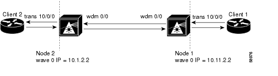
Figure 5-2 shows an unprotected topology with two nodes. Both nodes use channels 1-32 and use the following:
•
•
To troubleshoot a point-to-point configuration with only user level protection, you must visually check for irregular connections and component LEDs, check for system alarms or error messages, use the trial-and-error method, or replace components until you solve the problem.
Figure 5-2 Point-to-Point Configuration Without Protection
For an example configuration of an unprotected point-to-point topology, see the
Cisco ONS 15540 ESP Planning Guide.To troubleshoot the configuration and status of point-to-point unprotected topology, use the following EXEC commands:
Use the following steps to troubleshoot a point-to-point unprotected topology between two end user clients:
Step 1
The show interfaces transparent command indicates whether the connection between the Cisco ONS 15540 and the client equipment is up. See the "Troubleshooting Client Side Transparent Interfaces" section on page 3-1 for information about the fields in this display.
Step 2
The show interfaces wave command indicates whether the connection between the Cisco ONS 15540 and the neighboring node is up. See the Chapter 4, "Troubleshooting Trunk Side Interfaces," for information about the fields in this display.
Step 3
Using the ping command between the nodes over the OSC interface proves the connection between the two nodes has not failed. It does not prove that the individual channel connections have not been misconfigured or one of the patch connections or components has not failed.
For IP address configuration instructions for the OSC channel interface, refer to the
Cisco ONS 15540 ESP Configuration Guide and Command Reference.If these three steps have not found the failed connection between the nodes, continue with the following more disruptive connection loopback troubleshooting steps.
Caution
Step 4
Confirm the loopback configuration using the show interfaces transparent command. Loopback should appear as set in the show interfaces transparent display.
From the client equipment connected to node 1, confirm the connection to the client appears as looped back. This proves the connection from the client to the transparent interface on node 1 is working.
Note
Step 5
Confirm the loopback configuration using the show interfaces wave command. Loopback should appear as set in the show interfaces wave display.
From the client connection through node 1 to node 2, confirm the connection to the client is looped back. This proves the connection from the client to the wave interface on node 2 is working.
Step 6
Troubleshooting Point-to-Point Topology with Splitter Protection
Figure 5-3 shows a splitter protected topology with two nodes. Both nodes use channels 1-32 and use the following:
•
•
•
Note
For an example configuration of a splitter protected point-to-point topology, refer to the
Cisco ONS 15540 ESP Planning Guide.
Figure 5-3 Point-to-Point Connection with Splitter Protection
To troubleshoot the configuration and status of the point-to-point connection with splitter protection, use the following EXEC commands:
Follow these general steps to troubleshoot an optical fiber network connection between two end user clients on a splitter protected point-to-point topology:
Step 1
The show interfaces transparent command indicates whether the connection between the Cisco ONS 15540 and the client equipment is up. See the "Troubleshooting Client Side Transparent Interfaces" section on page 3-1 for information about the fields in this display.
Step 2
The show interfaces wave command indicates whether the connection between the Cisco ONS 15540 and the next optical fiber node is up. See the Chapter 4, "Troubleshooting Trunk Side Interfaces," for information about the fields in this display.
Step 3
If the connection fails, it could indicate a fiber failure in the west direction from node 1.
Step 4
The ping commands between the nodes proves the optical fiber connection between node 1 and node 2 in the west direction has failed and the standby connection in the east direction is working. It does not indicate if the individual channel connections have been misconfigured or one of the patch connections or components has failed.
For IP address configuration instructions for the OSC channel interface, refer to the
Cisco ONS 15540 ESP Configuration Guide and Command Reference.If these four steps have not found the failed connection between nodes, continue with the following more disruptive connection loopback troubleshooting steps.
Caution
Step 5
Confirm the loopback configuration using the show interfaces transparent command. The field Loopback set should appear in the show interfaces transparent display.
From the client equipment connected to node 1, confirm the connection to the client appears as looped back. This proves the connection from the client to the transparent interface on node 1 is working.
Note
Step 6
Confirm the loopback configuration using the show interfaces wave command.
The field Loopback set should appear in the show interfaces wave display.
From the client connection through node 1 to node 2, confirm the connection to the client is looped back. This proves the connection from the client to the wave interface on node 2 is working.
Step 7
Troubleshooting Point-to-Point Topology with Line Card Protection
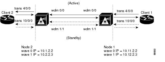
Figure 5-4 shows a line card protected topology with two nodes. Both nodes use channels 1-16 and use the following:
•
•
•
•
Figure 5-4 Point-to-Point Network with Line Card Protection
For an example configuration of a line card protected point-to-point topology, refer to the
Cisco ONS 15540 ESP Planning Guide.To troubleshoot the configuration and status of the point-to-point connection with line card protection, use the following EXEC commands:
Follow these general steps to troubleshoot point-to-point connections with line card protection between two end user clients:
Step 1
The show interfaces transparent command indicates whether the connection between the Cisco ONS 15540 and the client equipment is up. See the "Troubleshooting Client Side Transparent Interfaces" section on page 3-1 for information about the fields in this display.
Step 2
The show interfaces wave command indicates whether the connection between the Cisco ONS 15540 and the neighboring node is up. See the Chapter 4, "Troubleshooting Trunk Side Interfaces," for information about the fields in this display.
Step 3
Step 4
For IP address configuration instructions for the OSC channel interface, refer to the
Cisco ONS 15540 ESP Configuration Guide and Command Reference.If these four steps have not found the failed connection between the nodes, continue with the following more disruptive connection loopback troubleshooting steps.
Caution
Step 5
Confirm the loopback configuration using the show interfaces transparent command.
The field Loopback set should appear in the show interfaces transparent display.
From the client equipment connected to node 1, confirm the connection to the client appears as looped back. This proves the connection from the client to the transparent interface on node 1 is working.
Note
Step 6
Confirm the loopback configuration using the show interfaces wave command. The field Loopback set should appear in the show interfaces wave display.
From the client connection through node 1 to node 2, confirm the connection to the client is looped back. This proves the connection from the client to the wave interface on node 2 is working.
Step 7
Troubleshooting Hubbed Ring Topology with Splitter Protection
Figure 5-5 shows a network configured as a hubbed ring with splitter protection.
When a failure occurs between two nodes in a ring network, for example the failure between nodes 4 and 5 shown in Figure 5-5, alarms may appear on connections all around the network. For example, a "loss of signal" alarm may appear on the functioning connection between nodes 1 and 5 and a "loss of light" alarm may appear on the failed connection between nodes 4 and 5.
Note
For an example configuration of a splitter protected hubbed ring topology, refer to the
Cisco ONS 15540 ESP Planning Guide.Figure 5-5 Hubbed Ring Network with Splitter Protection
Figure 5-5 shows a splitter protected hubbed ring topology with five nodes. Node 1 and node 4 are configured as follows:
•
–
–
–
•
–
–
–
To troubleshoot the configuration and status of the optical connections in the hubbed ring with splitter protection, use the following EXEC commands:
Follow these steps to troubleshoot a splitter protected hubbed ring connection between two end user clients, shown in Figure 5-8:
Step 1
The show interfaces transparent command indicates whether the connection between the Cisco ONS 15540 and the client equipment is up. See the "Troubleshooting Client Side Transparent Interfaces" section on page 3-1 for information about the fields in this display.
Step 2
The show interfaces wave command indicates whether the connection between the Cisco ONS 15540 and the next optical fiber node is up. See the Chapter 4, "Troubleshooting Trunk Side Interfaces," for information about the fields in this display.
Step 3
If the connection fails, as in the previous example, this could indicate a fiber failure in the west direction from node 1.
Step 4
To determine which connections has failed, the connection between node 1 and node 5 or the connection between node 5 and node 4, use the same process to ping the processors over the OSC interface. This confirms the failure is a component of those two nodes or a cable in between node 5 and node 4.
For IP address configuration instructions for the OSC channel interface, refer to the
Cisco ONS 15540 ESP Configuration Guide and Command Reference.If these four steps have not found the failed connection between nodes continue with the following more disruptive connection loopback troubleshooting steps.
Caution
Step 5
Confirm the loopback configuration using the show interfaces transparent command.
The field Loopback set should appear in the show interfaces transparent display.
From the client equipment connected to node 1, confirm the connection to the client appears as looped back. This proves the connection from the client to the transparent interface on node 1 is working.
Note
Step 6
Confirm the loopback configuration using the show interfaces wave command. The field Loopback set should appear in the show interfaces wave display.
From the client connection through node 1 to node 4, confirm the connection to the client is looped back. This proves the connection from the client to the wave interface on node 4 is working.
Step 7
Troubleshooting Hubbed Ring Topology with Line Card Protection
Figure 5-6 shows a network configured as a hubbed ring with line card protection.
When a failure occurs between two nodes in a ring network, for example the failure between nodes 4 and 5 shown in Figure 5-6, alarms may appear on connections all around the network. For example, a "loss of signal" alarm may appear on the functioning connection between nodes 1 and 5 and a "loss of light" alarm may appear on the failed connection between nodes 4 and 5.
For an example configuration of a line card protected hubbed ring topology, refer to the
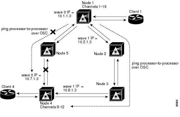
Cisco ONS 15540 ESP Planning Guide.Figure 5-6 Hubbed Ring Network with Line Card Protection
Figure 5-6 shows a line card protected hubbed ring topology with five nodes. Node 1 and node 4 are configured as follows:
•
–
–
–
–
•
–
–
–
–
For a detailed description of this configuration, refer to the Cisco ONS 15540 ESP Planning Guide.
The following steps describe the troubleshooting process needed to find the failed connection between node 4 and node 5 in Figure 5-6. This failure causes the active connection between nodes 1 and 4, through node 5, to automatically switch to the standby connection through nodes 2 and 3.
To troubleshoot the configuration and status of the optical connections in the hubbed ring with line card protection, use the following EXEC commands:
Follow these general steps to troubleshoot an optical fiber network connection between two end user clients in a hubbed ring network with line card protection.
Step 1
The show interfaces transparent command confirms whether the connection between the Cisco ONS 15540 and the client equipment is up. See the "Troubleshooting Client Side Transparent Interfaces" section on page 3-1 for information about the fields in this display.
Step 2
The show interfaces wave command indicates whether the connection between the Cisco ONS 15540 and the next optical fiber node is up.
Step 3
If the connection fails, this indicates a fiber failure in the west direction from node 1.
Step 4
The ping commands between the nodes proves the optical fiber connection between node 1 and node 4 in the west direction has failed and the standby connection in the east direction is working. It does not indicate if the individual channel connections have been misconfigured or one of the patch connections or components has failed.
To determine which connections have failed, the connection between node 1 and node 5 or the connection between node 5 and node 4, use the same process to ping the processors over the OSC interface. In this example, using the ping command to test the connection between node 1 and node 5 will work but the test from node 5 to node 4 will fail. This confirms the failure is a component of those two nodes or a cable in between node 5 and node 4.
If these four steps have not found the failed connection between nodes, continue with the following more disruptive connection loopback troubleshooting steps.
Caution
Step 5
Confirm the loopback configuration using the show interfaces transparent command.
The field Loopback set should appear in the show interfaces transparent display.
From the client connected to node 1, confirm the connection to the client is looped back. This proves the connection from the client to the transparent interface on node 1 is working.
Note
Step 6
Confirm the loopback configuration using the show interfaces wave command.
The field Loopback set should appear in the show interfaces wave display.
From the client connection through node 1 to node 4, confirm the connection to the client is looped back. This proves the connection from the client to the wave interface on node 4 is working.
If the wave loopback test of node 4 fails on all channels 9-12 that could indicate one of the following failures:
•
•
•
If the wave loopback test of node 4 fails on only one channel, for example channel 12, that could indicate the client connection to the transponder module for channel 12 has failed or the transponder has failed.
Note
From the client equipment connected to node 4, configure a loopback connection through the entire network end-to-end. This confirms the connection between the clients connected to node 1 and node 4 at both ends.
Troubleshooting Meshed Ring Topology with Splitter Protection
This section describes troubleshooting meshed ring network with splitter protection. A meshed ring is a physical ring that has the logical characteristics of a mesh. While traffic travels on a physical ring, the logical connections between individual nodes are meshed.
Figure 5-7 shows a network configured as a meshed ring with splitter protection.
When a failure occurs between two nodes in a ring network, for example the failure between nodes 3 and 4 shown in Figure 5-7, alarms may appear on connections all around the network. For example, a "loss of signal" alarm may appear on the functioning connection between nodes 1 and 4 and a "loss of light" alarm may appear on the failed connection between nodes 3 and 4.
Note
For an example configuration of a splitter protected meshed ring topology, refer to the
Cisco ONS 15540 ESP Planning Guide.Figure 5-7 Meshed Ring Network with Splitter Protection
Figure 5-7 shows a splitter protected meshed ring topology with four nodes. Node 1 and node 3 are configured as follows:
•
–
–
–
•
–
–
–
For an example of configuring a splitter protected meshed ring topology, refer to the Cisco ONS 15540 ESP Configuration Guide and Command Reference.
To troubleshoot the configuration and status of the optical connections in the meshed ring with splitter protection, use the following EXEC commands:
Follow these steps to troubleshoot a meshed ring topology with splitter protection between two end user clients:
Step 1
The show interfaces transparent command indicates whether the connection between the Cisco ONS 15540 and the client equipment is up. See the "Troubleshooting Client Side Transparent Interfaces" section on page 3-1 for information about the fields in this display.
Step 2
The show interfaces wave command indicates whether the connection between the Cisco ONS 15540 and the next optical fiber node is up. See the Chapter 4, "Troubleshooting Trunk Side Interfaces," for information about the fields in this display.
Step 3
If the connection fails, as in the previous example, this could indicate a fiber failure in the west direction from node 1.
Step 4
The ping commands between the nodes proves the optical fiber connection between node 1 and node 3 in the west direction has failed and the standby connection in the east direction is working. It does not indicate if the individual channel connections have been misconfigured or one of the patch connections or components has failed.
To determine which connection has failed, the connection between node 1 and node 4 or the connection between node 4 and node 3, use the same process to ping the processors over the OSC interface. In this example, using the ping command to test the connection between node 1 and node 4 will work but the test from node 4 to node 3 will fail. This confirms the failure is a component of those two nodes or a cable in between node 4 and node 3.
For IP address configuration instructions for the OSC channel interface, refer to the
Cisco ONS 15540 ESP Configuration Guide and Command Reference.If these four steps have not found the failed connection between nodes, continue with the following more disruptive connection loopback troubleshooting steps.
Caution
Step 5
Confirm the loopback configuration using the show interfaces transparent command. The field Loopback set should appear in the show interfaces transparent display.
From the client equipment connected to node 1, confirm the connection to the client appears as looped back. This proves the connection from the client to the transparent interface on node 1 is working.
Note
Step 6
Confirm the loopback configuration using the show interfaces wave command.
The field Loopback set should appear in the show interfaces wave display.
From the client connection through node 1 to node 3, confirm the connection to the client is looped back. This proves the connection from the client to the wave interface on node 3 is working.
Step 7
Troubleshooting Meshed Ring Topology with Line Card Protection
This section describes troubleshooting a connection over a meshed ring network with line card protection.
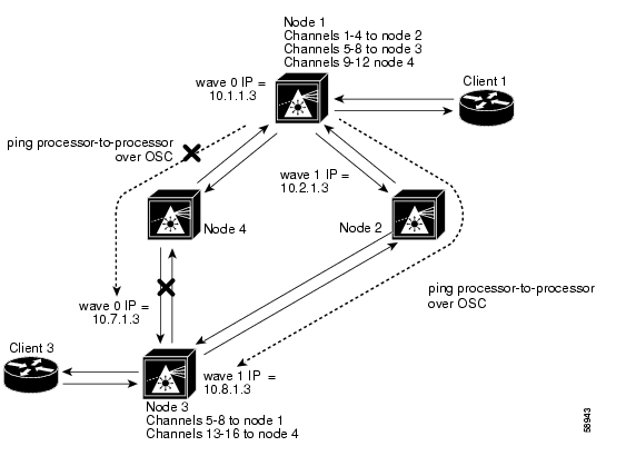
Figure 5-8 shows a network configured as a meshed ring with line card protection.
When a failure occurs between two nodes in a ring network, for example the failure between nodes 3 and 4 shown in Figure 5-8, alarms may appear on connections all around the network. For example, a "loss of signal" alarm may appear on the functioning connection between nodes 1 and 4 and a "loss of light" alarm may appear on the failed connection between nodes 3 and 4.
For an example configuration of a line card protected meshed ring topology, refer to the
Cisco ONS 15540 ESP Planning Guide.Figure 5-8 Meshed Ring Network with Line Card Protection
Figure 5-8 shows a line card protected meshed ring topology with four nodes. Node 1 and node 3 are configured as follows:
•
–
–
–
–
•
–
–
–
–
For a detailed description of this configuration, refer to the Cisco ONS 15540 ESP Planning Guide.
To troubleshoot the configuration and status of the optical connections in the meshed ring with line card protection, use the following EXEC commands:
Follow these steps to troubleshoot a line card protected meshed ring optical fiber network connection between two end user clients:
Step 1
The show interfaces transparent command indicates whether the connection between the Cisco ONS 15540 and the client equipment is up. See the "Troubleshooting Client Side Transparent Interfaces" section on page 3-1 for information about the fields in this display.
Step 2
The show interfaces wave command indicates whether the connection between the Cisco ONS 15540 and the next optical fiber node is up. See the Chapter 4, "Troubleshooting Trunk Side Interfaces," for information about the fields in this display.
Step 3
If the connection fails, as in the previous example, this could indicate a fiber failure in the west direction from node 1.
Step 4
The ping commands between the nodes proves the optical fiber connection between node 1 and node 4 in the west direction has failed and the standby connection in the east direction is working. It does not indicate if the individual channel connections have been misconfigured or one of the patch connections or components has failed.
To determine which connection has failed, the connection between node 1 and node 4 or the connection between node 4 and node 3, use the same process to ping the processors over the OSC interface. In this example, using the ping command to test the connection between node 1 and node 4 will work but the test from node 4 to node 3 will fail. This confirms the failure is a component of those two nodes or a cable between node 4 and node 3.
For IP address configuration instructions for the OSC channel interface, refer to the
Cisco ONS 15540 ESP Configuration Guide and Command Reference.If these four steps have not found the failed connection between nodes, continue with the following more disruptive connection loopback troubleshooting steps.
Caution
Step 5
The field Loopback set should appear in the show interfaces transparent display.
From the client equipment connected to node 1, confirm the connection to the client appears as looped back. This proves the connection from the client to the transparent interface on node 1 is working.
Note
Step 6
Confirm the loopback configuration using the show interfaces wave command.
The field Loopback set should appear in the show interfaces wave display.
From the client connection through node 1 to node 3, confirm the connection to the client is looped back. This proves the connection from the client to the wave interface on node 3 is working.
Step 7
![]()
![]()
![]()
![]()
![]()
![]()
![]()
![]()
Posted: Wed Mar 22 06:26:09 PST 2006
All contents are Copyright © 1992--2006 Cisco Systems, Inc. All rights reserved.
Important Notices and Privacy Statement.