|
|

Table Of Contents
Configuring Point-to-Point Topologies
About Point-to-Point Topologies
Configuring a Point-to-Point Topology with Splitter Protection
Configuring a Point-to-Point Topology with Line Card Protection
Configuring an Unprotected Point-to-Point Topology
Configuring Point-to-Point Topologies
This chapter describes how to configure point-to-point topologies. This chapter contains the following sections:
•
About Point-to-Point Topologies
•
•
•
About Point-to-Point Topologies
In a point-to-point topology, two Cisco ONS 15540 ESP systems are connected to each other in the network. Each of the systems originates and terminates all configured channels. You can use splitter protection to protect against fiber failure, or line card protection to protect against both the fiber and transponder failures. To also protect against client failure, you can implement protection on the client equipment itself.
Note
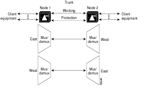
Up to 32 client signals in splitter protection mode, or 16 client signals in line card protection mode, are optically multiplexed at each end and are multiplexed onto a single fiber pair. Figure 7-1 shows an example of this topology using two DWDM fiber links, one working and one protection.
Figure 7-1 Protected Point-to-Point Topology Example
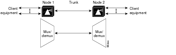
Figure 7-2 shows an example of an unprotected point-to-point topology using one unprotected DWDM fiber link.
Figure 7-2 Unprotected Point-to-Point Topology Example
Point-to-point topologies have many common applications, including extending the reach of Gigabit Ethernet or SONET in long-haul transport.
Note
For more information on point-to-point topologies, refer to the
Cisco ONS 15540 ESP Planning and Design Guide.Configuring a Point-to-Point Topology with Splitter Protection
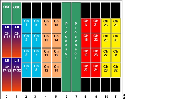
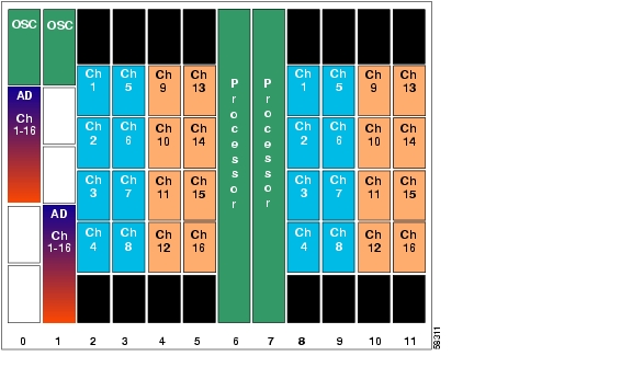
Figure 7-3 shows how the modules are installed in the shelf for a 32-channel point-to-point topology.Thirty-two client signals of any supported protocol are carried over the trunk fiber, which is protected. This scenario assumes that splitter protection is being used and the working path is through slot 0 on both nodes.
Figure 7-3 Shelf Configuration for Splitter Protected 32-Channel Point-to-Point Topology
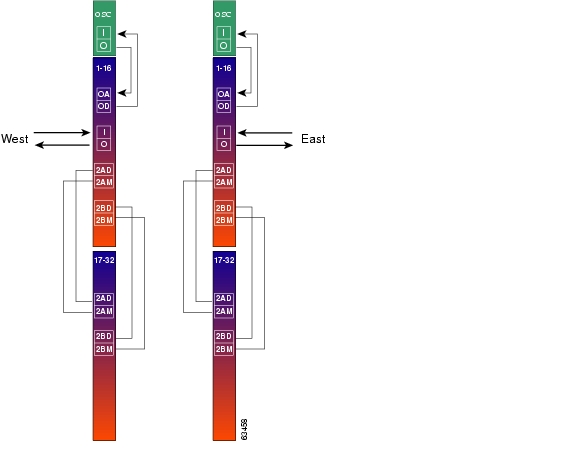
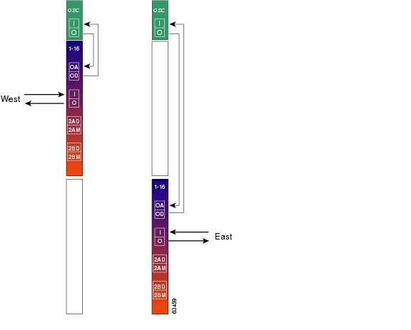
Figure 7-4 shows how the terminal mux/demux modules are cabled for the 32-channel splitter protected point-to-point configuration.
Figure 7-4 Terminal Mux/Demux Module Cabling with OSC for Splitter Protected 32-Channel Point-to-Point Topology
Patch Connections
Node1# configure terminalNode1(config)# patch wave 0 oscfilter 0/0Node1(config)# patch wave 1 oscfilter 1/0Node1(config)# patch filterband 0/0/0 filtergroup 0/2/0Node1(config)# patch filterband 0/0/1 filtergroup 0/2/1Node1(config)# patch filterband 1/0/0 filtergroup 1/2/0Node1(config)# patch filterband 1/0/1 filtergroup 1/2/1Transparent Interfaces
Node1(config)# interface transparent 2/0/0Node1(config-if)# encapsulation sonet oc12Node1(config-if)#monitor enableNode1(config-if)#exit<Configure the remaining transparent interfaces in the shelf>APS
Node1(config)# redundancyNode1(config-red)# associate interface wavepatch */*/0 wavepatch */*/1 enableNode1(config-red)# endNode1# copy system:running-config nvram:startup-configRepeat the entire preceding configuration on node 2.
Configuring a Point-to-Point Topology with Line Card Protection
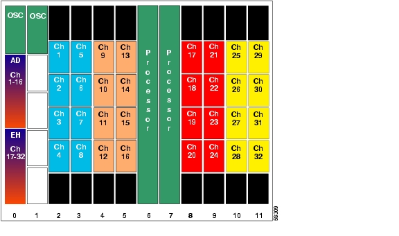
Figure 7-5 shows how the modules are installed in the shelf for a 16-channel point-to-point topology with line card protection. Sixteen client signals of any supported protocol are carried over the trunk fiber, which is also protected.
Note
Figure 7-5 Shelf Configuration for Line Card Protected 32-Channel Point-to-Point Topology
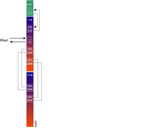
Figure 7-6 shows how the terminal mux/demux modules are cabled for the 16-channel line card protected point-to-point configuration.
Figure 7-6 Terminal Mux/Demux Module Cabling with OSC for Line Card Protected 16-Channel Point-to-Point Topology
Node 1
Patch Connections
Node1#configure terminalNode1(config)# patch wave 0 oscfilter 0/0Node1(config)# patch wave 1 oscfilter 1/2Transparent Interfaces
Node1(config)# interface transparent 2/0/0Node1(config-if)# encapsulation sonet oc12Node1(config-if)# monitor enableNode1(config-if)# exit<Configure the remaining transparent interfaces in the shelf>APS
Use the following commands to configure y-cable protection. The working path is through slot 0.
Node1(config)# redundancyNode1(config-red)# associate group channel1Node1(config-red-aps)# aps working transparent 2/0/0Node1(config-red-aps)# aps protection transparent 8/0/0Node1(config-red-aps)# aps y-cableNode1(config-red-aps)# aps enableNode1(config-red-aps)# exitNode1(config-red)# associate group channel2Node1(config-red-aps)# aps working transparent 2/1/0Node1(config-red-aps)# aps protection transparent 8/1/0Node1(config-red-aps)# aps y-cableNode1(config-red-aps)# aps enableNode1(config-red-aps)# exitNode1(config-red)# associate group channel3Node1(config-red-aps)# aps working transparent 2/2/0Node1(config-red-aps)# aps protection transparent 8/2/0Node1(config-red-aps)# aps y-cableNode1(config-red-aps)# aps enableNode1(config-red-aps)# exitNode1(config-red)# associate group channel4Node1(config-red-aps)# aps working transparent 2/3/0Node1(config-red-aps)# aps protection transparent 8/3/0Node1(config-red-aps)# aps y-cableNode1(config-red-aps)# aps enableNode1(config-red-aps)# exitNode1(config-red)# associate group channel5Node1(config-red-aps)# aps working transparent 3/0/0Node1(config-red-aps)# aps protection transparent 9/0/0Node1(config-red-aps)# aps y-cableNode1(config-red-aps)# aps enableNode1(config-red-aps)# exitNode1(config-red)# associate group channel6Node1(config-red-aps)# aps working transparent 3/1/0Node1(config-red-aps)# aps protection transparent 9/1/0Node1(config-red-aps)# aps y-cableNode1(config-red-aps)# aps enableNode1(config-red-aps)# exitNode1(config-red)# associate group channel7Node1(config-red-aps)# aps working transparent 3/2/0Node1(config-red-aps)# aps protection transparent 9/2/0Node1(config-red-aps)# aps y-cableNode1(config-red-aps)# aps enableNode1(config-red-aps)# exitNode1(config-red)# associate group channel8Node1(config-red-aps)# aps working transparent 3/3/0Node1(config-red-aps)# aps protection transparent 9/3/0Node1(config-red-aps)# aps y-cableNode1(config-red-aps)# aps enableNode1(config-red-aps)# exitNode1(config-red)# associate group channel9Node1(config-red-aps)# aps working transparent 4/0/0Node1(config-red-aps)# aps protection transparent 10/0/0Node1(config-red-aps)# aps y-cableNode1(config-red-aps)# aps enableNode1(config-red-aps)# exitNode1(config-red)# associate group channel10Node1(config-red-aps)# aps working transparent 4/1/0Node1(config-red-aps)# aps protection transparent 10/1/0Node1(config-red-aps)# aps y-cableNode1(config-red-aps)# aps enableNode1(config-red-aps)# exitNode1(config-red)# associate group channel11Node1(config-red-aps)# aps working transparent 4/2/0Node1(config-red-aps)# aps protection transparent 10/2/0Node1(config-red-aps)# aps y-cableNode1(config-red-aps)# aps enableNode1(config-red-aps)# exitNode1(config-red)# associate group channel12Node1(config-red-aps)# aps working transparent 4/3/0Node1(config-red-aps)# aps protection transparent 10/3/0Node1(config-red-aps)# aps y-cableNode1(config-red-aps)# aps enableNode1(config-red-aps)# exitNode1(config-red)# associate group channel13Node1(config-red-aps)# aps working transparent 5/0/0Node1(config-red-aps)# aps protection transparent 11/0/0Node1(config-red-aps)# aps y-cableNode1(config-red-aps)# aps enableNode1(config-red-aps)# exitNode1(config-red)# associate group channel14Node1(config-red-aps)# aps working transparent 5/1/0Node1(config-red-aps)# aps protection transparent 11/0/0Node1(config-red-aps)# aps y-cableNode1(config-red-aps)# aps enableNode1(config-red-aps)# exitNode1(config-red)# associate group channel15Node1(config-red-aps)# aps working transparent 5/2/0Node1(config-red-aps)# aps protection transparent 11/2/0Node1(config-red-aps)# aps y-cableNode1(config-red-aps)# aps enableNode1(config-red-aps)# exitNode1(config-red)# associate group channel16Node1(config-red-aps)# aps working transparent 5/3/0Node1(config-red-aps)# aps protection transparent 11/3/0Node1(config-red-aps)# aps y-cableNode1(config-red-aps)# aps enableNode1(config-red-aps)# endNode1# copy system:running-config nvram:startup-configRepeat the entire preceding configuration on node 2.
Configuring an Unprotected Point-to-Point Topology
Figure 7-7 shows how the modules are installed in the shelf for a 32-channel point-to-point topology without protection.
Figure 7-7 Shelf Configuration for Unprotected 32-Channel Point-to-Point Topology
Figure 7-8 shows how the terminal mux/demux modules are cabled for the 32-channel unprotected point-to-point configuration.
Figure 7-8 Terminal Mux/Demux Module Cabling with OSC for Unprotected 32-Channel Point-to-Point Topology
Patch Connections
Node 1
Node1#configure terminalNode1(config)# patch wave 0 oscfilter 0/0Node1(config)# patch filterband 0/0/0 filtergroup 0/2/0Node1(config)# patch filterband 0/0/1 filtergroup 0/2/1Node 2
Node2#configure terminalNode2(config)#patch wave 0 oscfilter 0/0Node2(config)#patch filterband 0/0/0 filtergroup 0/2/0Node2(config)#patch filterband 0/0/1 filtergroup 0/2/1Transparent Interfaces
Node 1
Node1(config)# interface transparent 2/0/0Node1(config-if)# encapsulation sonet oc12Node1(config-if)# monitor enableNode1(config-if)# exit<Configure the remaining transparent interfaces in the shelf>Node1# copy system:running-config nvram:startup-configNode 2
Node2(config)#interface transparent 2/0/0Node2(config-if)#encapsulation sonet oc12Node2(config-if)#monitor enableNode2(config-if)#end<Configure the remaining transparent interfaces in the shelf>Node2# copy system:running-config nvram:startup-config
![]()
![]()
![]()
![]()
![]()
![]()
![]()
![]()
Posted: Wed Mar 22 04:37:11 PST 2006
All contents are Copyright © 1992--2006 Cisco Systems, Inc. All rights reserved.
Important Notices and Privacy Statement.