|
|

Table Of Contents
Configuring Line Card Protected Dual Shelf Nodes
Configuring and Cabling the Shelves
Configuring Connections Between Shelves
Configuring Dual Shelf Nodes
This chapter describes how to configure a dual shelf node in a network topology. This chapter contains the following sections:
•
Configuring Line Card Protected Dual Shelf Nodes
About Dual Shelf Nodes
On a single Cisco ONS 15540 shelf, only 16 channels can be supported with line card protection. By cascading two Cisco ONS 15540 shelves, up to 32 channels can be supported with line card protection. You can use dual shelf nodes in either a point-to-point topology or a ring topology. The OSCs (optical supervisory channels) can both connect to one shelf, or they can be split between the two shelves.
Configuring Line Card Protected Dual Shelf Nodes
To configure a dual shelf node with line card protection, follow these steps:
Step 1
Step 2
For more information on patch connections, see the "About Patch Connections" section on page 4-20.
Step 3
For information on configuring network access, see the "Configuring IP Access on the NME Interface" section on page 3-3.
Step 4
For information on configuring IP address on the OSC wave interface, see the "Configuring IP on the OSC" section on page 9-8.
Step 5
Step 6
Configuring and Cabling the Shelves
You can use either terminal or add/drop mux/demux modules in a dual shelf node. For configurations with 32 channels with line card protection, we recommend using the 16-channel terminal mux/demux module. For configurations with fewer than 32 channels in line card protection, use 8-channel add/drop mux/demux modules as often as possible.
Terminal Mux/Demux Modules for 32-Channels
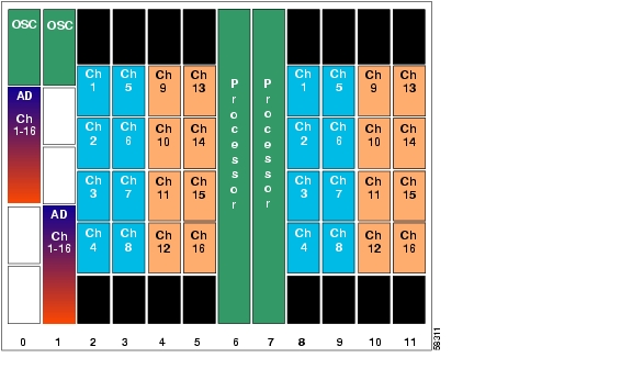
Shelf 1 is configured for channels 1-16 with OSC, while shelf 2 is configured for channels 17-32 without OSC. The mux/demux modules are patched between the two shelves as if they were in the same shelf.
Figure 6-1 shows how the modules are installed for shelf 1 in the line card protected 32-channel configuration.
Figure 6-1 Shelf 1 Configuration for 32 Channels with Terminal Mux/Demux Modules and Line Card Protection
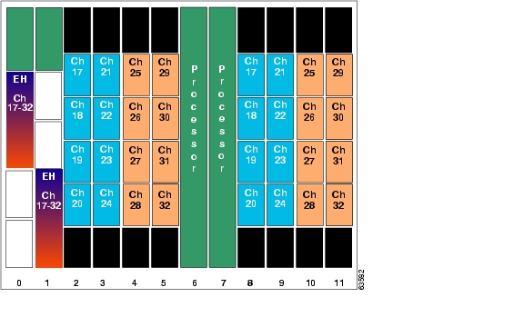
The configuration for shelf 2 is shown in Figure 6-2. As in shelf 1, the west line card motherboards are used in slots 2-5, and the east line card motherboards are used in slots 8-11.
Figure 6-2 Shelf 2 Configuration for 32 Channels with Terminal Mux/Demux Modules and Line Card Protection
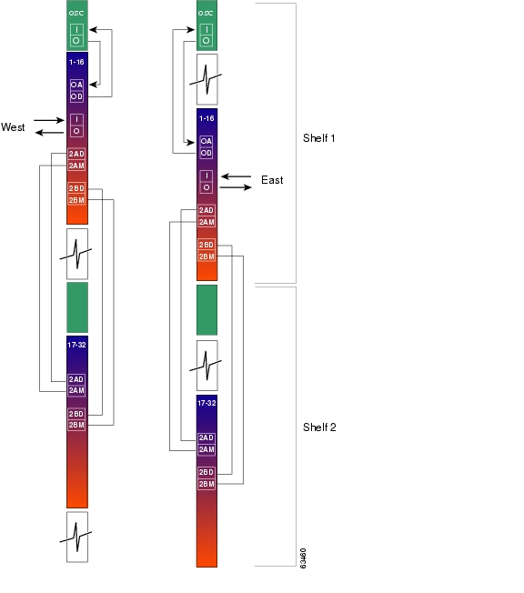
Figure 6-3 shows how the terminal mux/demux modules are cabled between the two shelves to support all 32 channels on both the east and west sides.
Figure 6-3 Terminal Mux/Demux Module Cabling with Two Shelves with 32 Channels and Line Card Protection
Add/Drop Mux/Demux Modules for 24-Channels
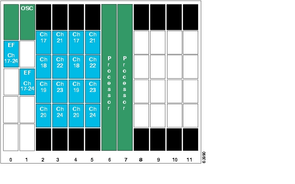
Shelf 1 is configured for channels 1-16 with OSC to the west and shelf 2 is configured for channels 17-24 with OSC to the east. The mux/demux modules are patched between the two shelves as if they were in the same shelf.
Figure 6-4 shows how the modules are installed for shelf 1 in the line card protected 24-channel configuration.
Figure 6-4 Shelf 1 Configuration for 24 Channels with Add/Drop Mux/Demux Modules and Line Card Protection
The configuration for shelf 2 is shown in Figure 6-5. As in shelf 1, the west line card motherboards are used in slots 2-5, and the east line card motherboards are used in slots 8-11.
Figure 6-5 Shelf 2 Configuration for 24 Channels with Add/Drop Mux/Demux Modules and Line Card Protection
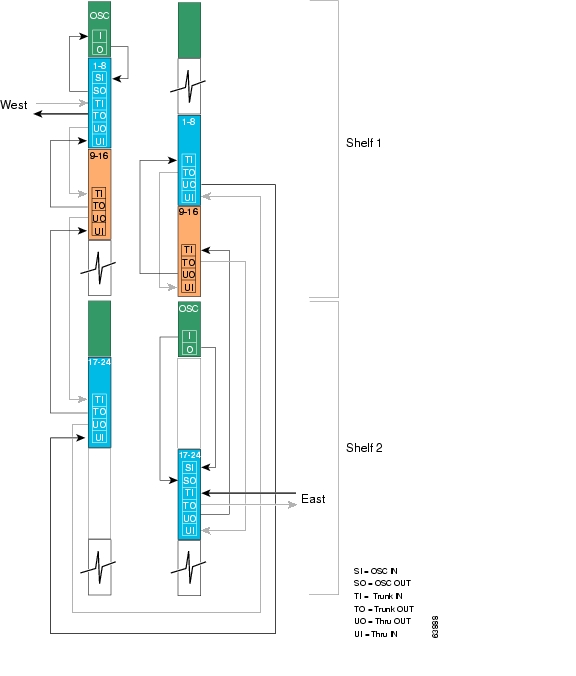
Figure 6-6 shows how the terminal mux/demux modules are cabled between the two shelves to support 24 channels on both the east and west sides.
Figure 6-6 Add/Drop Mux/Demux Module Cabling with Two Shelves with 24 Channels and Line Card Protection
Configuring Connections Between Shelves
To include the two shelves as one node in the network topology, you must configure the patch connection between the shelves in the CLI (command-line interface). To configure these connections, use the following commands, beginning in global configuration mode:
Note
Examples
The following example shows how to configure the patch connections between the terminal mux/demux modules on the two shelves in the node:
Shelf1(config)# interface filterband 0/0/0Shelf1(config-if)# topology neighbor name shelf2 port name filtergroup 0/0/0Shelf1(config-if)# topology neighbor agent ip-address 10.1.2.3Shelf1(config-if)# exitShelf1(config)# interface filterband 0/0/1Shelf1(config-if)# topology neighbor name shelf2 port name filtergroup 0/0/1Shelf1(config-if)# topology neighbor agent ip-address 10.1.2.3Shelf1(config-if)# exitShelf1(config)# interface filterband 1/2/0Shelf1(config-if)# topology neighbor name shelf2 port name filtergroup 1/2/0Shelf1(config-if)# topology neighbor agent ip-address 10.1.2.3Shelf1(config-if)# exitShelf1(config)# interface filterband 1/2/1Shelf1(config-if)# topology neighbor name shelf2 port name filtergroup 1/2/1Shelf1(config-if)# topology neighbor agent ip-address 10.1.2.3Shelf2(config)# interface filtergroup 0/0/0Shelf2(config-if)# topology neighbor name shelf1 port name filterband 0/0/0Shelf2(config-if)# topology neighbor agent ip-address 10.2.2.4Shelf2(config-if)# exitShelf2(config)# interface filtergroup 0/0/1Shelf2(config-if)# topology neighbor name shelf1 port name filterband 0/0/1Shelf2(config-if)# topology neighbor agent ip-address 10.2.2.4Shelf2(config-if)# exitShelf2(config)# interface filtergroup 1/2/0Shelf2(config-if)# topology neighbor name shelf1 port name filterband 1/2/0Shelf2(config-if)# topology neighbor agent ip-address 10.2.2.4Shelf2(config-if)# exitShelf2(config)# interface filtergroup 1/2/1Shelf2(config-if)# topology neighbor name shelf1 port name filterband 1/2/1Shelf2(config-if)# topology neighbor agent ip-address 10.2.2.4The following example shows how to configure the patch connections between the add/drop mux/demux modules on the two shelves in the node:
Shelf1(config)# interface thru 0/3Shelf1(config-if)# topology neighbor name shelf2 port name wdm 0/0Shelf1(config-if)# topology neighbor agent ip-address 10.2.2.4Shelf1(config-if)# exitShelf1(config)# interface wdm 1/3Shelf1(config-if)# topology neighbor name shelf2 port name thru 1/0Shelf1(config-if)# topology neighbor agent ip-address 10.2.2.4Shelf1(config-if)# exitShelf2(config)# interface wdm 0/0Shelf2(config-if)# topology neighbor name shelf1 port name thru 0/3Shelf2(config-if)# topology neighbor agent ip-address 10.2.2.4Shelf2(config-if)# exitShelf2(config)# interface thru 1/0Shelf2(config-if)# topology neighbor name shelf1 port name wdm 0/0Shelf2(config-if)# topology neighbor agent ip-address 10.2.2.4Shelf2(config-if)# exitConfiguring APS
When a dual shelf node is part of a network topology, the channels supported by it might require special configuration. On a dual shelf node, the OSC might have only one connection, such as the configuration shown in Figure 6-4, or no OSC connections at all, such as the configuration shown in Figure 6-2. For the APS Channel Protocol to function correctly, the shelves that support a channel must both have two OSC connections, or you must configure the APS group name and IP address information on the shelves.
To configure APS for a channel supported on a dual shelf node without full OSC support, perform the following steps, beginning in global configuration mode:
For more information on configuring y-cable line card protection, refer to the "About Line Card Protection" section on page 5-6.
Examples
For these examples, assume the following:
•
•
•
•
The following example shows how to configure channels 17-20 on the single shelf node:
Switch(config)# redundancySwitch(config-red)# associate group Channel17Switch(config-red-aps)# aps working transparent 2/0/0Switch(config-red-aps)# aps protection transparent 4/0/0Switch(config-red-aps)# aps y-cableSwitch(config-red-aps)# aps far-end group Channel17 ip-address 10.1.2.3Switch(config-red-aps)# aps enableSwitch(config-red-aps)# exitSwitch(config-red)# associate group Channel18Switch(config-red-aps)# aps working transparent 2/1/0Switch(config-red-aps)# aps protection transparent 4/1/0Switch(config-red-aps)# aps y-cableSwitch(config-red-aps)# aps far-end group Channel18 ip-address 10.1.2.3Switch(config-red-aps)# aps enableSwitch(config-red-aps)# exitSwitch(config-red)# associate group Channel19Switch(config-red-aps)# aps working transparent 2/2/0Switch(config-red-aps)# aps protection transparent 4/2/0Switch(config-red-aps)# aps y-cableSwitch(config-red-aps)# aps far-end group Channel19 ip-address 10.1.2.3Switch(config-red-aps)# aps enableSwitch(config-red-aps)# exitSwitch(config-red)#associate group Channel20Switch(config-red-aps)# aps working transparent 2/3/0Switch(config-red-aps)# aps protection transparent 4/3/0Switch(config-red-aps)# aps y-cableSwitch(config-red-aps)# aps far-end group Channel20 ip-address 10.1.2.3Switch(config-red-aps)# aps enableSwitch(config-red-aps)#endSwitch# copy system:running-config nvram:startup-configThe following example shows how to configure channels 17-20 on shelf 2 of a dual shelf node.
Shelf2(config)# redundancyShelf2(config-red)#associate group Channel17Shelf2(config-red-aps)# aps working transparent 2/0/0Shelf2(config-red-aps)# aps protection transparent 4/0/0Shelf2(config-red-aps)# aps y-cableShelf2(config-red-aps)# aps far-end group Channel17 ip-address 10.3.2.1Shelf2(config-red-aps)# aps enableShelf2(config-red-aps)# exitShelf2(config-red)# associate group Channel18Shelf2(config-red-aps)# aps working transparent 2/1/0Shelf2(config-red-aps)# aps protection transparent 4/1/0Shelf2(config-red-aps)# aps y-cableShelf2(config-red-aps)# aps far-end group Channel18 ip-address 10.3.2.1Shelf2(config-red-aps)# aps enableShelf2(config-red-aps)# exitShelf2(config-red)# associate group Channel19Shelf2(config-red-aps)# aps working transparent 2/2/0Shelf2(config-red-aps)# aps protection transparent 4/2/0Shelf2(config-red-aps)# aps y-cableShelf2(config-red-aps)# aps far-end group Channel19 ip-address 10.3.2.1Shelf2(config-red-aps)# aps enableShelf2(config-red-aps)# exitShelf2(config-red)# associate group Channel20Shelf2(config-red-aps)# aps working transparent 2/3/0Shelf2(config-red-aps)# aps protection transparent 4/3/0Shelf2(config-red-aps)# aps y-cableShelf2(config-red-aps)# aps far-end group Channel20 ip-address 10.3.2.1Shelf2(config-red-aps)# aps enableShelf2(config-red-aps)# endShelf2# copy system:running-config nvram:startup-config
![]()
![]()
![]()
![]()
![]()
![]()
![]()
![]()
Posted: Thu Aug 19 16:58:19 PDT 2004
All contents are Copyright © 1992--2004 Cisco Systems, Inc. All rights reserved.
Important Notices and Privacy Statement.