|
|

Table Of Contents
Configuring a Hubbed Ring with Splitter Protection and OSC
Configuring a Hubbed Ring with Line Card Protection and OSC
Configuring a Meshed Ring with Splitter Protection and OSC
Configuring a Splitter Protected Meshed Ring with Unprotected Channels and OSC
Configuring a Meshed Ring with Line Card Protection and OSC
Configuring a Line Card Protected Meshed Ring with Unprotected Channels and OSC
Configuring Ring Topologies
This chapter describes how to configure the Cisco ONS 15540 in two-fiber topologies and provides example configurations for hubbed ring and meshed ring topologies using optical add/drop multiplexing. This chapter includes the following sections:
•
Configuring a Hubbed Ring with Splitter Protection and OSC
•
•
•
•
•
About Ring Topologies
A ring topology is a network of three or more nodes each of which connects to two other nodes to form a "ring". Ring topologies support splitter protected, line card protected, and unprotected configurations. On a ring, traffic is transmitted in both directions from each node; traffic is received from only one direction. In case of a fiber failure, the node switches over to receive traffic from the other direction.
The Cisco ONS 15540 supports hubbed ring and meshed ring topologies.
Note
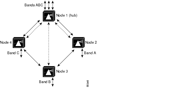
Hubbed Ring Topologies
In a hubbed ring topology, all channels originate and terminate on the hub node (node1 in Figure 8-1). The other nodes on the ring, sometimes called satellite nodes, add and drop one or more channels. The added and dropped channels terminate at the node, while the channels that are not being dropped (express channels) are passed through optically, without being electrically terminated.
Figure 8-1 Hubbed Ring Topology Example
For more information on hubbed ring topologies, refer to the Introduction to DWDM Technology document and the Cisco ONS 15540 ESP Planning and Design Guide.
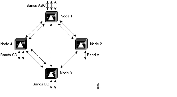
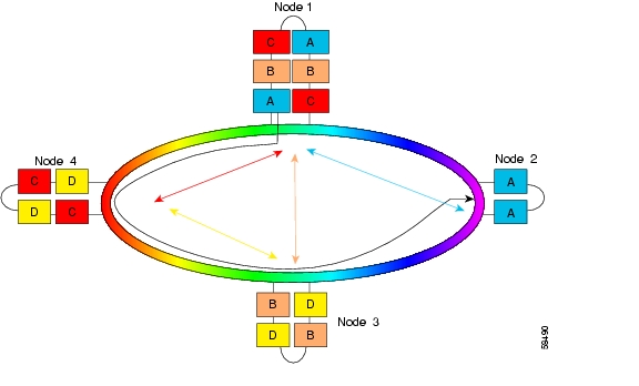
Meshed Ring Topologies
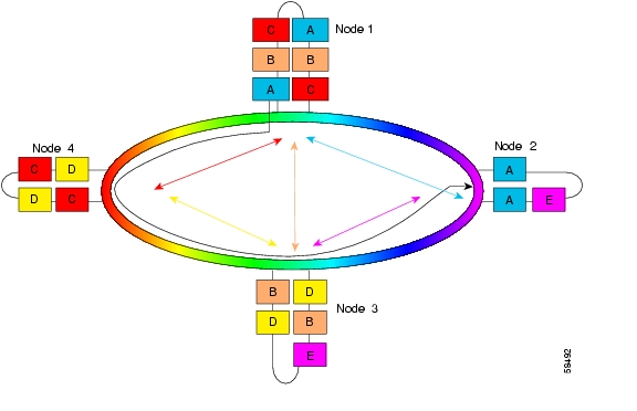
A meshed ring is a physical ring that has the characteristics of a mesh. Figure 8-2 shows an example of this type of configuration, which is sometimes called a logical mesh. While all traffic travels around the physical ring, nodes 1 and node 3 share band B (channels 5-8), and nodes 3 and node 4 share band D (channels 29-32). Hence there is a logical mesh overlay on the ring.
Protection options and optical link loss budget considerations are the same as in a hubbed ring configuration.
Figure 8-2 Meshed Ring Topology Example
For more information on meshed ring topologies, refer to the Introduction to DWDM Technology document and the Cisco ONS 15540 ESP Planning and Design Guide.
Configuring a Hubbed Ring with Splitter Protection and OSC
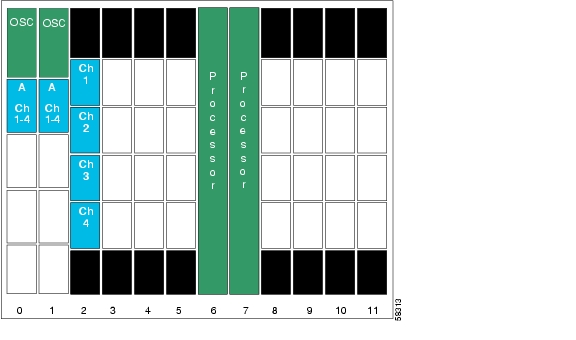
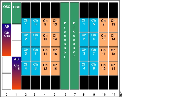
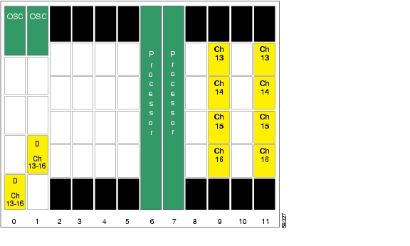
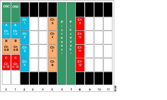
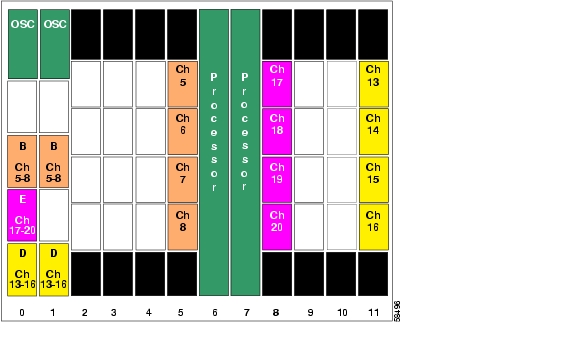
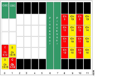
Figure 8-3 shows an example topology of a three-node hubbed ring. Node 1 is the hub configured with band A through band D (channels 1-16). Node 2 adds and drops band A (channels 1-4), node 3 adds and drops band B (channels 5-8), node 4 adds and drops band C (channels 9-12), and node 5 adds and drops band D (channels 13-16). The transponders carry Gigabit Ethernet traffic.
Figure 8-3 Hubbed Ring Channel Plan
Node 1
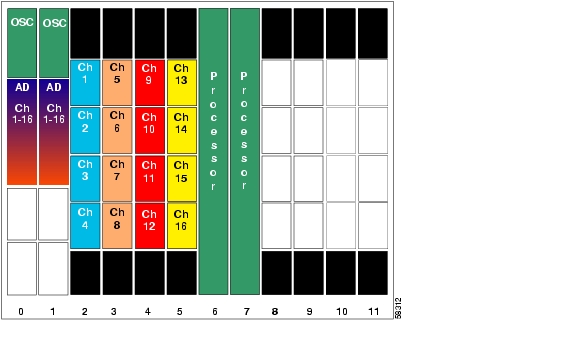
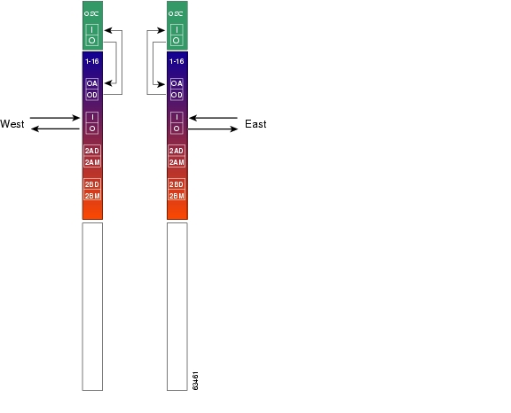
Figure 8-4 shows how the modules are installed in the shelf for node 1 in the example network shown in Figure 8-3. The shelf is populated for the 16-channel splitter protected hub node. Splitter protected line card motherboards are installed in slots 2-5, and the 16-channel mux/demux modules are used in the east and west mux/demux slots.
Figure 8-4 Shelf Configuration for 16-Channel Hub Node in Splitter Protected Hubbed Ring
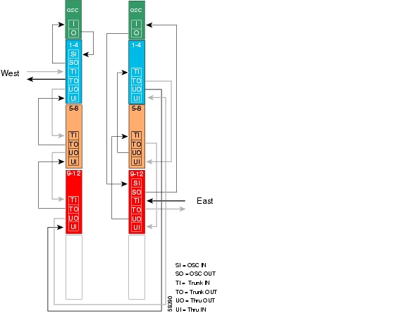
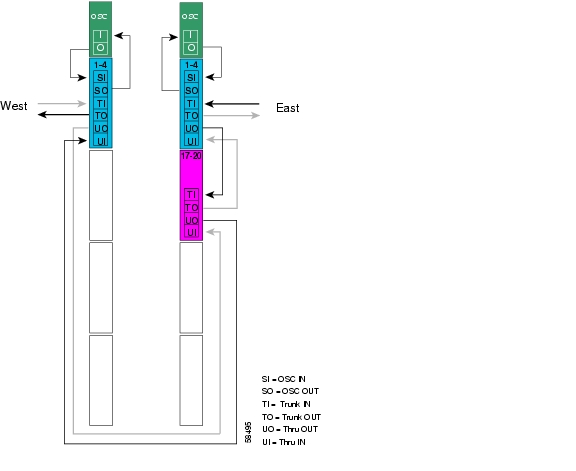
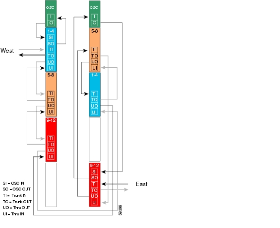
Figure 8-5 shows how the 16-channel mux/demux modules are cabled for the hub node in the splitter protected hubbed ring shown in Figure 8-3.
Figure 8-5 Terminal Mux/Demux Module Cabling with OSC for 16-Channel Hub Node in Splitter Protected Hubbed Ring
Patch Connections
Node1#configure terminalNode1(config)#patch wave 0 oscfilter 0/0Node1(config)#patch wave 1 oscfilter 1/0Transparent Interfaces
Node1(config)#interface transparent 2/0/0Node1(config-if)#encapsulation gigabitethernetNode1(config-if)#monitor enableNode1(config-if)#exit<Configure the remaining transparent interfaces in the shelf>OSC Interfaces
Node1(config)#interface wave 0Node1(config-if)#no shutdownNode1(config-if)#exitNode1(config)#interface wave 1Node1(config-if)#no shutdownNode1(config-if)#exitAPS
Node1(config)#redundancyNode1(config-red)#associate group wavepatch channel1Node1(config-red-aps)#aps working wavepatch 2/0/1Node1(config-red-aps)#aps protection wavepatch 2/0/0Node1(config-red-aps)#aps enableNode1(config-red-aps)#exitNode1(config-red)#associate group wavepatch channe2Node1(config-red-aps)#aps working wavepatch 2/1/1Node1(config-red-aps)#aps protection wavepatch 2/1/0Node1(config-red-aps)#aps enableNode1(config-red-aps)#exitNode1(config-red)#associate group wavepatch channel3Node1(config-red-aps)#aps working wavepatch 2/2/1Node1(config-red-aps)#aps protection wavepatch 2/2/0Node1(config-red-aps)#aps enableNode1(config-red-aps)#exitNode1(config-red)#associate group wavepatch channel4Node1(config-red-aps)#aps working wavepatch 2/3/1Node1(config-red-aps)#aps protection wavepatch 2/3/0Node1(config-red-aps)#aps enableNode1(config-red-aps)#exitNode1(config-red)#associate group wavepatch channel5Node1(config-red-aps)#aps working wavepatch 3/0/1Node1(config-red-aps)#aps protection wavepatch 3/0/0Node1(config-red-aps)#aps enableNode1(config-red-aps)#exitNode1(config-red)#associate group wavepatch channe6Node1(config-red-aps)#aps working wavepatch 3/1/1Node1(config-red-aps)#aps protection wavepatch 3/1/0Node1(config-red-aps)#aps enableNode1(config-red-aps)#exitNode1(config-red)#associate group wavepatch channel7Node1(config-red-aps)#aps working wavepatch 3/2/1Node1(config-red-aps)#aps protection wavepatch 3/2/0Node1(config-red-aps)#aps enableNode1(config-red-aps)#exitNode1(config-red)#associate group wavepatch channel8Node1(config-red-aps)#aps working wavepatch 3/3/1Node1(config-red-aps)#aps protection wavepatch 3/3/0Node1(config-red-aps)#aps enableNode1(config-red-aps)#exitNode1(config-red)#associate group wavepatch channel9Node1(config-red-aps)#aps working wavepatch 4/0/0Node1(config-red-aps)#aps protection wavepatch 4/0/1Node1(config-red-aps)#aps enableNode1(config-red-aps)#exitNode1(config-red)#associate group wavepatch channe110Node1(config-red-aps)#aps working wavepatch 4/1/0Node1(config-red-aps)#aps protection wavepatch 4/1/1Node1(config-red-aps)#aps enableNode1(config-red-aps)#exitNode1(config-red)#associate group wavepatch channel11Node1(config-red-aps)#aps working wavepatch 4/2/0Node1(config-red-aps)#aps protection wavepatch 4/2/1Node1(config-red-aps)#aps enableNode1(config-red-aps)#exitNode1(config-red)#associate group wavepatch channel12Node1(config-red-aps)#aps working wavepatch 4/3/0Node1(config-red-aps)#aps protection wavepatch 4/3/1Node1(config-red-aps)#aps enableNode1(config-red-aps)#exitNode1(config-red)#associate group wavepatch channel13Node1(config-red-aps)#aps working wavepatch 5/0/0Node1(config-red-aps)#aps protection wavepatch 5/0/1Node1(config-red-aps)#aps enableNode1(config-red-aps)#exitNode1(config-red)#associate group wavepatch channe114Node1(config-red-aps)#aps working wavepatch 5/1/0Node1(config-red-aps)#aps protection wavepatch 5/1/1Node1(config-red-aps)#aps enableNode1(config-red-aps)#exitNode1(config-red)#associate group wavepatch channel15Node1(config-red-aps)#aps working wavepatch 5/2/0Node1(config-red-aps)#aps protection wavepatch 5/2/1Node1(config-red-aps)#aps enableNode1(config-red-aps)#exitNode1(config-red)#associate group wavepatch channel16Node1(config-red-aps)#aps working wavepatch 5/3/0Node1(config-red-aps)#aps protection wavepatch 5/3/1Node1(config-red-aps)#aps enableNode1(config-red-aps)#endNode1#copy system:running-config nvram:startup-configNode 2
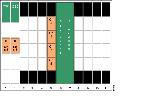
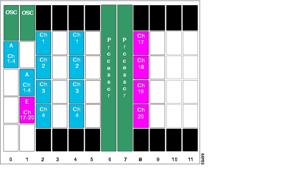
Figure 8-6 shows the shelf configuration for node 2 in the example hubbed ring network shown in Figure 8-3. A splitter protected line card motherboard is used in slot 2, and 4-channel mux/demux modules are used in subcard 0 of the east and west mux/demux slots.
Figure 8-6 Shelf Configuration for Node 2 in Splitter Protected Hubbed Ring
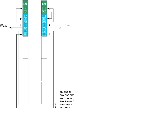
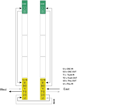
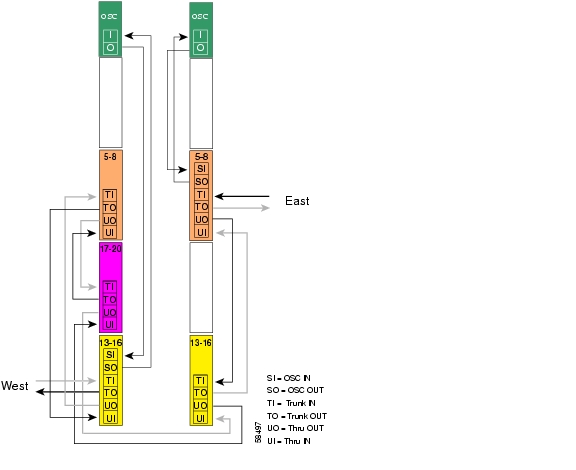
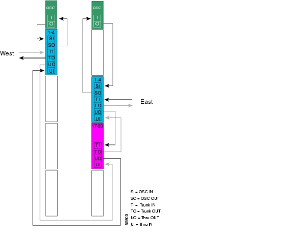
Figure 8-7 shows how the 4-channel mux/demux modules are cabled for node 2 in the splitter protected hubbed ring shown in Figure 8-3.
Figure 8-7 Add/Drop Mux/Demux Module Cabling with OSC for Node 2 in Splitter Protected Hubbed Ring
Patch Connections
Node2#configure terminalNode2(config)#patch thru 0/0 thru 1/0Node2(config)#patch wave 0 oscfilter 0/0Node2(config)#patch wave 1 oscfilter 1/0Transparent Interfaces in Slot 2
Node2(config)#interface transparent 2/0/0Node2(config-if)#encapsulation gigabitethernetNode2(config-if)#monitor enableNode2(config-if)#exit<Configure the remaining transparent interfaces in the slot>OSC Interfaces
Node2(config)#interface wave 0Node2(config-if)#no shutdownNode2(config-if)#exitNode2(config)#interface wave 1Node2(config-if)#no shutdownNode2(config-if)#exitAPS
Node2(config)#redundancyNode2(config-red)#associate group wavepatch channel1Node2(config-red-aps)#aps working wavepatch 2/0/0Node2(config-red-aps)#aps protection wavepatch 2/0/1Node2(config-red-aps)#aps enableNode2(config-red-aps)#exitNode2(config-red)#associate group wavepatch channel2Node2(config-red-aps)#aps working wavepatch 2/1/0Node2(config-red-aps)#aps protection wavepatch 2/1/1Node2(config-red-aps)#aps enableNode2(config-red-aps)#exitNode2(config-red)#associate group wavepatch channel3Node2(config-red-aps)#aps working wavepatch 2/2/0Node2(config-red-aps)#aps protection wavepatch 2/2/1Node2(config-red-aps)#aps enableNode2(config-red-aps)#exitNode2(config-red)#associate group wavepatch channel4Node2(config-red-aps)#aps working wavepatch 2/3/0Node2(config-red-aps)#aps protection wavepatch 2/3/1Node2(config-red-aps)#aps enableNode2(config-red-aps)#endNode2#copy system:running-config nvram:startup-configNode 3
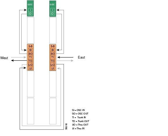
Figure 8-8 shows the shelf configuration for node 3 in the example hubbed ring network shown in Figure 8-3. A splitter protected line card motherboard is used in slot 5, and 4-channel mux/demux modules are used in subcard 1 of the east and west mux/demux slots.
Figure 8-8 Shelf Configuration for Node 3 in Splitter Protected Hubbed Ring
Figure 8-9 shows how the 4-channel mux/demux modules are cabled for node 3 in the splitter protected hubbed ring network shown in Figure 8-3.
Figure 8-9 Add/Drop Mux/Demux Module Cabling with OSC for Node 3 in Splitter Protected Hubbed Ring
Patch Connections
Node3#configure terminalNode3(config)#patch thru 0/1 thru 1/1Node3(config)#patch wave 0 oscfilter 0/1Node3(config)#patch wave 1 oscfilter 1/1Transparent Interfaces in Slot 5
Node3(config)#interface transparent 5/0/0Node3(config-if)#encapsulation gigabitethernetNode3(config-if)#monitor enableNode3(config-if)#exit<Configure the remaining transparent interfaces in the slot>OSC Interfaces
Node3(config)#interface wave 0Node3(config-if)#no shutdownNode3(config-if)#exitNode3(config)#interface wave 1Node3(config-if)#no shutdownNode3(config-if)#exitAPS
Node3(config)#redundancyNode3(config-red)#associate group wavepatch channel5Node3(config-red-aps)#aps working wavepatch 5/0/0Node3(config-red-aps)#aps protection wavepatch 5/0/1Node3(config-red-aps)#aps enableNode3(config-red-aps)#exitNode3(config-red)#associate group wavepatch channel6Node3(config-red-aps)#aps working wavepatch 5/1/0Node3(config-red-aps)#aps protection wavepatch 5/1/1Node3(config-red-aps)#aps enableNode3(config-red-aps)#exitNode3(config-red)#associate group wavepatch channel7Node3(config-red-aps)#aps working wavepatch 5/2/0Node3(config-red-aps)#aps protection wavepatch 5/2/1Node3(config-red-aps)#aps enableNode3(config-red-aps)#exitNode3(config-red)#associate group wavepatch channel8Node3(config-red-aps)#aps working wavepatch 5/3/0Node3(config-red-aps)#aps protection wavepatch 5/3/1Node3(config-red-aps)#aps enableNode3(config-red-aps)#endNode3#copy system:running-config nvram:startup-configNode 4
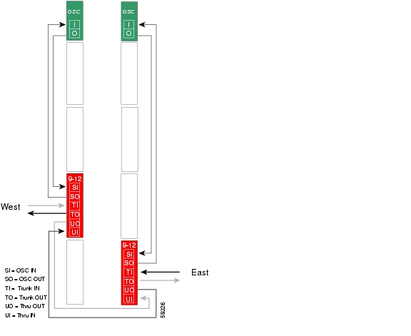
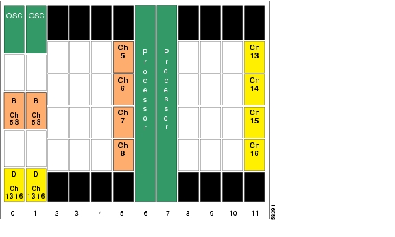
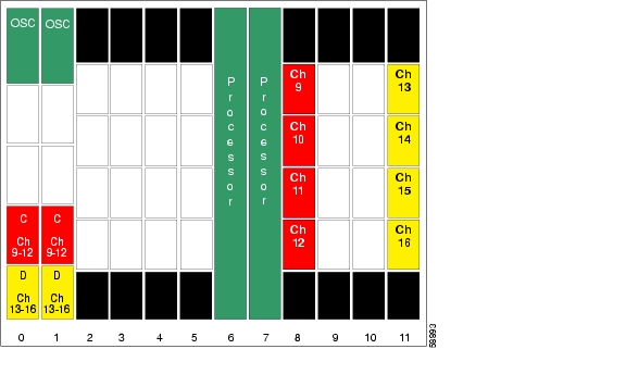
Figure 8-10 shows the shelf configuration for node 4 in the hubbed ring network shown in Figure 8-3. A splitter protected line card motherboard is used in slot 8, and 4-channel mux/demux modules are used in subcard 2 of the east and west mux/demux slots.
Figure 8-10 Shelf Configuration for Node 4 in Splitter Protected Hubbed Ring
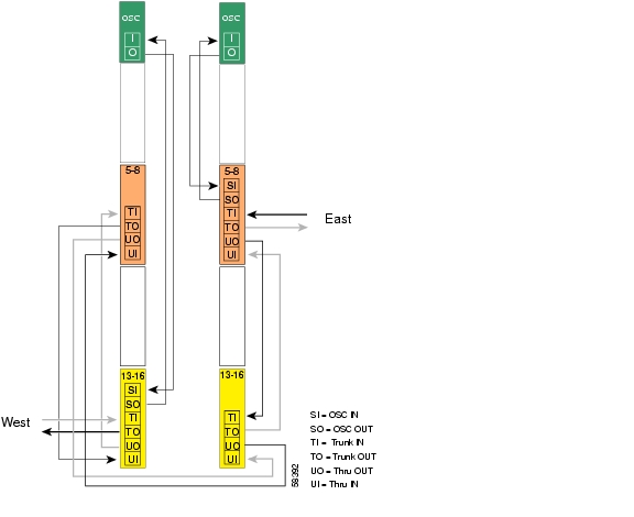
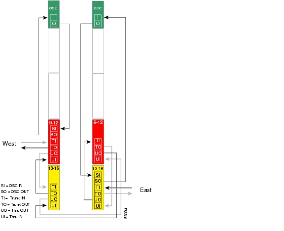
Figure 8-11 shows how the 4-channel mux/demux modules are cabled for node 4 in the splitter protected hubbed ring network shown in Figure 8-3.
Figure 8-11 Add/Drop Mux/Demux Module Cabling with OSC for Node 4 in Splitter Protected Hubbed Ring
Patch Connections
Node4#configure terminalNode4(config)#patch thru 0/2 thru 1/2Node4(config)#patch wave 0 oscfilter 0/2Node4(config)#patch wave 1 oscfilter 1/2Transparent Interfaces in Slot 8
Node4(config)#interface transparent 8/0/0Node4(config-if)#encapsulation gigabitethernetNode4(config-if)#monitor enableNode4(config-if)#exit<Configure the remaining transparent interfaces in the slot>OSC Interfaces
Node4(config)#interface wave 0Node4(config-if)#no shutdownNode4(config-if)#exitNode4(config)#interface wave 1Node4(config-if)#no shutdownNode4(config-if)#exitAPS
Node4(config)#redundancyNode4(config-red)#associate group channel9Node4(config-red-aps)#aps working wavepatch 8/0/1Node4(config-red-aps)#aps protection wavepatch 8/0/0Node4(config-red-aps)#aps enableNode4(config-red-aps)#exitNode4(config-red)#associate group channel10Node4(config-red-aps)#aps working wavepatch 8/1/1Node4(config-red-aps)#aps protection wavepatch 8/1/0Node4(config-red-aps)#aps enableNode4(config-red-aps)#exitNode4(config-red)#associate group channel11Node4(config-red-aps)#aps working wavepatch 8/2/1Node4(config-red-aps)#aps protection wavepatch 8/2/0Node4(config-red-aps)#aps enableNode4(config-red-aps)#exitNode4(config-red)#associate group channel12Node4(config-red-aps)#aps working wavepatch 8/3/1Node4(config-red-aps)#aps protection wavepatch 8/3/0Node4(config-red-aps)#aps enableNode4(config-red-aps)#exitNode4(config-red-aps)#endNode4#copy system:running-config nvram:startup-configNode 5
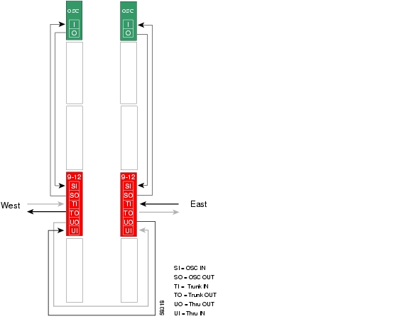
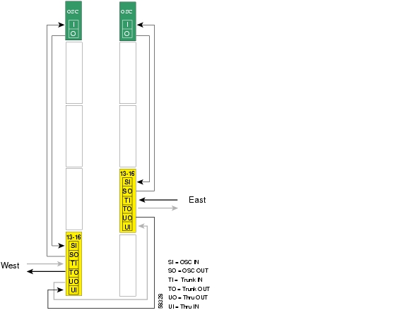
Figure 8-12 shows the shelf configuration for node 5 in the example network shown in Figure 8-3. A splitter protected line card motherboard is used in slot 11, and 4-channel mux/demux modules are used in subcard 3 of the east and west mux/demux slots.
Figure 8-12 Shelf Configuration for Node 5 in Splitter Protected Hubbed Ring
Figure 8-13 shows how the 4-channel mux/demux modules are cabled for node 5 in the example network shown in Figure 8-3.
Figure 8-13 Add/Drop Mux/Demux Module Cabling with OSC for Node 5 in Splitter Protected Hubbed Ring
Patch Connections
Node5#configure terminalNode5(config)#patch thru 0/3 thru 1/3Node5(config)#patch wave 0 oscfilter 0/3Node5(config)#patch wave 1 oscfilter 1/3Transparent Interfaces in Slot 11
Node5(config)#interface transparent 11/0/0Node5(config-if)#encapsulation gigabitethernetNode5(config-if)#monitor enableNode5(config-if)#exit<Configure the remaining transparent interfaces in the slot>OSC Interfaces
Node5(config)#interface wave 0Node5(config-if)#no shutdownNode5(config-if)#exitNode5(config)#interface wave 1Node5(config-if)#no shutdownNode5(config-if)#exitAPS
Node5(config)#redundancyNode5(config-red)#associate group channel13Node5(config-red-aps)#aps working wavepatch 11/0/1Node5(config-red-aps)#aps protection wavepatch 11/0/0Node5(config-red-aps)#aps enableNode5(config-red-aps)#exitNode5(config-red)#associate group channel14Node5(config-red-aps)#aps working wavepatch 11/1/1Node5(config-red-aps)#aps protection wavepatch 11/1/0Node5(config-red-aps)#aps enableNode5(config-red-aps)#exitNode5(config-red)#associate group channel15Node5(config-red-aps)#aps working wavepatch 11/2/1Node5(config-red-aps)#aps protection wavepatch 11/2/0Node5(config-red-aps)#aps enableNode5(config-red-aps)#exitNode5(config-red)#associate group channel16Node5(config-red-aps)#aps working wavepatch 11/3/1Node5(config-red-aps)#aps protection wavepatch 11/3/0Node5(config-red-aps)#aps enableNode5(config-red-aps)#exitNode5(config-red-aps)#endNode5#copy system:running-config nvram:startup-configConfiguring a Hubbed Ring with Line Card Protection and OSC
Line card protection requires a different shelf and CLI configuration from splitter protection. The following sections describe an example based on the hubbed ring topology shown in Figure 8-3.
Note
Node 1
Figure 8-14 shows the shelf configuration for the hub node in the hubbed ring example shown in Figure 8-3. The line card motherboards in slots 2-5 are west motherboards, corresponding to the 16-channel mux/demux module in the west mux/demux slot; the line card motherboards in slots 8-11 are east motherboards, corresponding to the 16-channel mux/demux module in the east mux/demux slot.
Figure 8-14 Shelf Configuration for Hub Node in Line Card Protected Hubbed Ring
Figure 8-15 shows how the 16-channel mux/demux modules are cabled for node 1 in the hub node in the line card protected hubbed ring shown in Figure 8-3.
Figure 8-15 Terminal Mux/Demux Module Cabling with OSC for Hub Node in Line Card Protected Hubbed Ring
Patch Connections
Node1#configure terminalNode1(config)#patch wave 0 oscfilter 0/0Node1(config)#patch wave 1 oscfilter 1/2Transparent Interfaces
Node1(config)#interface transparent 2/0/0Node1(config-if)#encapsulation gigabitethernetNode1(config-if)#monitor enableNode1(config-if)#exit<Configure the remaining transparent interfaces in the shelf>OSC Interfaces
Node1(config)#interface wave 0Node1(config-if)#no shutdownNode1(config-if)#exitNode1(config)#interface wave 1Node1(config-if)#no shutdownNode1(config-if)#exitAPS
Use the following for configuring y-cable protection.
Node1(config)#redundancyNode1(config-red)#associate group channel1Node1(config-red-aps)#aps working transparent 8/0/0Node1(config-red-aps)#aps protection transparent 2/0/0Node1(config-red-aps)#aps y-cableNode1(config-red-aps)#aps revertiveNode1(config-red-aps)#aps enableNode1(config-red-aps)#exitNode1(config-red)#associate group channel2Node1(config-red-aps)#aps working transparent 8/1/0Node1(config-red-aps)#aps protection transparent 2/1/0Node1(config-red-aps)#aps y-cableNode1(config-red-aps)#aps revertiveNode1(config-red-aps)#aps enableNode1(config-red-aps)#exitNode1(config-red)#associate group channel3Node1(config-red-aps)#aps working transparent 8/2/0Node1(config-red-aps)#aps protection transparent 2/2/0Node1(config-red-aps)#aps y-cableNode1(config-red-aps)#aps revertiveNode1(config-red-aps)#aps enableNode1(config-red-aps)#exitNode1(config-red)#associate group channel4Node1(config-red-aps)#aps working transparent 8/3/0Node1(config-red-aps)#aps protection transparent 2/3/0Node1(config-red-aps)#aps y-cableNode1(config-red-aps)#aps revertiveNode1(config-red-aps)#aps enableNode1(config-red-aps)#exitNode1(config-red)#associate group channel5Node1(config-red-aps)#aps working transparent 9/0/0Node1(config-red-aps)#aps protection transparent 3/0/0Node1(config-red-aps)#aps y-cableNode1(config-red-aps)#aps revertiveNode1(config-red-aps)#aps enableNode1(config-red-aps)#exitNode1(config-red)#associate group channel6Node1(config-red-aps)#aps working transparent 9/1/0Node1(config-red-aps)#aps protection transparent 3/1/0Node1(config-red-aps)#aps y-cableNode1(config-red-aps)#aps revertiveNode1(config-red-aps)#aps enableNode1(config-red-aps)#exitNode1(config-red)#associate group channel7Node1(config-red-aps)#aps working transparent 9/2/0Node1(config-red-aps)#aps protection transparent 3/2/0Node1(config-red-aps)#aps y-cableNode1(config-red-aps)#aps revertiveNode1(config-red-aps)#aps enableNode1(config-red-aps)#exitNode1(config-red)#associate group channel8Node1(config-red-aps)#aps working transparent 9/3/0Node1(config-red-aps)#aps protection transparent 3/3/0Node1(config-red-aps)#aps y-cableNode1(config-red-aps)#aps revertiveNode1(config-red-aps)#aps enableNode1(config-red-aps)#exitNode1(config-red)#associate group channel9Node1(config-red-aps)#aps working transparent 4/0/0Node1(config-red-aps)#aps protection transparent 10/0/0Node1(config-red-aps)#aps y-cableNode1(config-red-aps)#aps revertiveNode1(config-red-aps)#aps enableNode1(config-red-aps)#exitNode1(config-red)#associate group channel10Node1(config-red-aps)#aps working transparent 4/1/0Node1(config-red-aps)#aps protection transparent 10/1/0Node1(config-red-aps)#aps y-cableNode1(config-red-aps)#aps revertiveNode1(config-red-aps)#aps enableNode1(config-red-aps)#exitNode1(config-red)#associate group channel11Node1(config-red-aps)#aps working transparent 4/2/0Node1(config-red-aps)#aps protection transparent 10/2/0Node1(config-red-aps)#aps y-cableNode1(config-red-aps)#aps revertiveNode1(config-red-aps)#aps enableNode1(config-red-aps)#exitNode1(config-red)#associate group channel12Node1(config-red-aps)#aps working transparent 4/3/0Node1(config-red-aps)#aps protection transparent 10/3/0Node1(config-red-aps)#aps y-cableNode1(config-red-aps)#aps revertiveNode1(config-red-aps)#aps enableNode1(config-red-aps)#exitNode1(config-red)#associate group channel13Node1(config-red-aps)#aps working transparent 5/0/0Node1(config-red-aps)#aps protection transparent 11/0/0Node1(config-red-aps)#aps y-cableNode1(config-red-aps)#aps revertiveNode1(config-red-aps)#aps enableNode1(config-red-aps)#exitNode1(config-red)#associate group channel14Node1(config-red-aps)#aps working transparent 5/1/0Node1(config-red-aps)#aps protection transparent 11/1/0Node1(config-red-aps)#aps y-cableNode1(config-red-aps)#aps revertiveNode1(config-red-aps)#aps enableNode1(config-red-aps)#exitNode1(config-red)#associate group channel15Node1(config-red-aps)#aps working transparent 5/2/0Node1(config-red-aps)#aps protection transparent 11/2/0Node1(config-red-aps)#aps y-cableNode1(config-red-aps)#aps revertiveNode1(config-red-aps)#aps enableNode1(config-red-aps)#exitNode1(config-red)#associate group channel16Node1(config-red-aps)#aps working transparent 5/3/0Node1(config-red-aps)#aps protection transparent 11/3/0Node1(config-red-aps)#aps y-cableNode1(config-red-aps)#aps revertiveNode1(config-red-aps)#aps enableNode1(config-red-aps)#endNode1#copy system:running-config nvram:startup-configNode 2
Figure 8-16 shows the shelf configuration for node 2 in the line card protected hubbed ring shown in Figure 8-3. Slot 2 uses a west line card motherboard, corresponding to the add/drop mux/demux module in the west mux/demux slot; slot 4 uses an east line card motherboard, corresponding to the add/drop mux/demux module in the east mux/demux slot.
Figure 8-16 Shelf Configuration for Node 2 in Line Card Protected Hubbed Ring
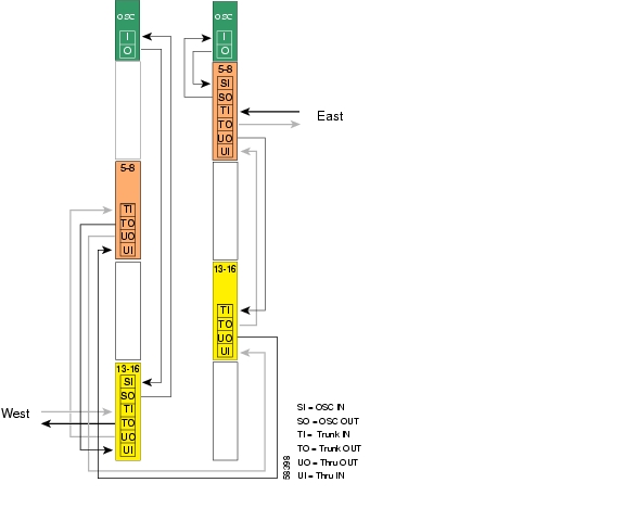
Figure 8-17 shows how the 4-channel mux/demux modules are cabled for node 2 in the line card protected hubbed ring shown in Figure 8-3.
Figure 8-17 Add/Drop Mux/Demux Module Cabling with OSC for Node 2 in Line Card Protected Hubbed Ring
Patch Connections
Node2#configure terminalNode2(config)#patch thru 0/0 thru 1/1Node2(config)#patch wave 0 oscfilter 0/0Node2(config)#patch wave 1 oscfilter 1/1Transparent Interfaces in Slot 2
Node2(config)#interface transparent 2/0/0Node2(config-if)#encapsulation gigabitethernetNode2(config-if)#monitor enableNode2(config-if)#exit<Configure the remaining transparent interfaces in the slot>Transparent Interfaces in Slot 4
Node2(config)#interface transparent 4/0/0Node2(config-if)#encapsulation gigabitethernetNode2(config-if)#monitor enableNode2(config-if)#exit<Configure the remaining transparent interfaces in the slot>OSC Interfaces
Node2(config)#interface wave 0Node2(config-if)#no shutdownNode2(config-if)#exitNode2(config)#interface wave 1Node2(config-if)#no shutdownNode2(config-if)#exitAPS
Use the following for configuring y-cable protection.
Node2(config)#redundancyNode2(config-red)#associate group channel1Node2(config-red-aps)#aps working transparent 2/0/0Node2(config-red-aps)#aps protection transparent 4/0/0Node2(config-red-aps)#aps y-cableNode2(config-red-aps)#aps revertiveNode2(config-red-aps)#aps enableNode2(config-red-aps)#exitNode2(config-red)#associate group channel2Node2(config-red-aps)#aps working transparent 2/1/0Node2(config-red-aps)#aps protection transparent 4/1/0Node2(config-red-aps)#aps y-cableNode2(config-red-aps)#aps revertiveNode2(config-red-aps)#aps enableNode2(config-red-aps)#exitNode2(config-red)#associate group channel3Node2(config-red-aps)#aps working transparent 2/2/0Node2(config-red-aps)#aps protection transparent 4/2/0Node2(config-red-aps)#aps y-cableNode2(config-red-aps)#aps revertiveNode2(config-red-aps)#aps enableNode2(config-red-aps)#exitNode2(config-red)#associate group channel4Node2(config-red-aps)#aps working transparent 2/3/0Node2(config-red-aps)#aps protection transparent 4/3/0Node2(config-red-aps)#aps y-cableNode2(config-red-aps)#aps revertiveNode2(config-red-aps)#aps enableNode2(config-red-aps)#endNode2#copy system:running-config nvram:startup-configNode 3
Figure 8-18 shows the shelf configuration for node 3 in the line card protected hubbed ring shown in Figure 8-3. Slot 3 uses an east line card motherboard, corresponding to the add/drop mux/demux module in the east mux/demux slot; slot 5 uses a west line card motherboard, corresponding to the add/drop mux/demux module in the west mux/demux slot.
Figure 8-18 Shelf Configuration for Node 3 in Line Card Protected Hubbed Ring
Figure 8-19 shows how the 4-channel mux/demux modules are cabled for node 3 in the line card protected hubbed ring shown in Figure 8-3.
Figure 8-19 Add/Drop Mux/Demux Module Cabling with OSC for Node 3 in Line Card Protected Hubbed Ring
Patch Connections
Node3#configure terminalNode3(config)#patch thru 0/1 thru 1/0Node3(config)#patch wave 0 oscfilter 0/1Node3(config)#patch wave 1 oscfilter 1/0Transparent Interfaces in Slot 3
Node3(config)#interface transparent 3/0/0Node3(config-if)#encapsulation gigabitethernetNode3(config-if)#monitor enableNode3(config-if)#exit<Configure the remaining transparent interfaces in the slot>Transparent Interfaces in Slot 5
Node3(config)#interface transparent 5/0/0Node3(config-if)#encapsulation gigabitethernetNode3(config-if)#monitor enableNode3(config-if)#exit<Configure the remaining transparent interfaces in the slot>OSC Interfaces
Node3(config)#interface wave 0Node3(config-if)#no shutdownNode3(config-if)#exitNode3(config)#interface wave 1Node3(config-if)#no shutdownNode3(config-if)#exitAPS
Use the following for configuring y-cable protection.
Node3(config)#redundancyNode3(config-red)#associate group channel5Node3(config-red-aps)#aps working transparent 5/0/0Node3(config-red-aps)#aps protection transparent 3/0/0Node3(config-red-aps)#aps y-cableNode3(config-red-aps)#aps revertiveNode3(config-red-aps)#aps enableNode3(config-red-aps)#exitNode3(config-red)#associate group channel6Node3(config-red-aps)#aps working transparent 5/1/0Node3(config-red-aps)#aps protection transparent 3/1/0Node3(config-red-aps)#aps y-cableNode3(config-red-aps)#aps revertiveNode3(config-red-aps)#aps enableNode3(config-red-aps)#exitNode3(config-red)#associate group channel7Node3(config-red-aps)#aps working transparent 5/2/0Node3(config-red-aps)#aps protection transparent 3/2/0Node3(config-red-aps)#aps y-cableNode3(config-red-aps)#aps revertiveNode3(config-red-aps)#aps enableNode3(config-red-aps)#exitNode3(config-red)#associate group channel8Node3(config-red-aps)#aps working transparent 5/3/0Node3(config-red-aps)#aps protection transparent 3/3/0Node3(config-red-aps)#aps y-cableNode3(config-red-aps)#aps revertiveNode3(config-red-aps)#aps enableNode3(config-red-aps)#endNode3#copy system:running-config nvram:startup-configNode 4
Figure 8-20 shows the shelf configuration for node 4 in the line card protected hubbed ring shown in Figure 8-3. Slot 8 uses a west line card motherboard, corresponding to the add/drop mux/demux module in the west mux/demux slot; slot 10 uses an east line card motherboard, corresponding to the add/drop mux/demux module in the east mux/demux slot.
Figure 8-20 Module Installation Configuration for Node 4
Figure 8-21 shows how the 4-channel mux/demux modules are cabled for node 4 in the line card protected hubbed ring shown in Figure 8-3.
Figure 8-21 Add/Drop Mux/Demux Module Cabling with OSC for Node 4 in Line Card Protected Hubbed Ring
Patch Connections
Node4#configure terminalNode4(config)#patch thru 0/2 thru 1/3Node4(config)#patch wave 0 oscfilter 0/2Node4(config)#patch wave 1 oscfilter 1/3Transparent Interfaces in Slot 8
Node4(config)#interface transparent 8/0/0Node4(config-if)#encapsulation gigabitethernetNode4(config-if)#monitor enableNode4(config-if)#exit<Configure the remaining transparent interfaces in the slot>Transparent Interfaces in Slot 10
Node4(config)#interface transparent 10/0/0Node4(config-if)#encapsulation gigabitethernetNode4(config-if)#monitor enableNode4(config-if)#exit<Configure the remaining transparent interfaces in the slot>OSC Interfaces
Node4(config)#interface wave 0Node4(config-if)#no shutdownNode4(config-if)#exitNode4(config)#interface wave 1Node4(config-if)#no shutdownNode4(config-if)#exitAPS
Use the following for configuring y-cable protection.
Node4(config)#redundancyNode4(config-red)#associate group channel9Node4(config-red-aps)#aps working transparent 10/0/0Node4(config-red-aps)#aps protection transparent 8/0/0Node4(config-red-aps)#aps y-cableNode4(config-red-aps)#aps revertiveNode4(config-red-aps)#aps enableNode4(config-red-aps)#exitNode4(config-red)#associate group channel10Node4(config-red-aps)#aps working transparent 10/1/0Node4(config-red-aps)#aps protection transparent 8/1/0Node4(config-red-aps)#aps y-cableNode4(config-red-aps)#aps revertiveNode4(config-red-aps)#aps enableNode4(config-red-aps)#exitNode4(config-red)#associate group channel11Node4(config-red-aps)#aps working transparent 10/2/0Node4(config-red-aps)#aps protection transparent 8/2/0Node4(config-red-aps)#aps y-cableNode4(config-red-aps)#aps revertiveNode4(config-red-aps)#aps enableNode4(config-red-aps)#exitNode4(config-red)#associate group channel12Node4(config-red-aps)#aps working transparent 10/3/0Node4(config-red-aps)#aps protection transparent 8/3/0Node4(config-red-aps)#aps y-cableNode4(config-red-aps)#aps revertiveNode4(config-red-aps)#aps enableNode4(config-red-aps)#endNode4#copy system:running-config nvram:startup-configNode 5
Figure 8-22 shows the shelf configuration for node 5 in the line card protected hubbed ring shown in Figure 8-3. Slot 9 uses an east line card motherboard, corresponding to the add/drop mux/demux module in the east mux/demux slot; slot 11 uses a west line card motherboard, corresponding to the add/drop mux/demux module in the west mux/demux slot.
Figure 8-22 Shelf Configuration for Node 5 in Line Card Protected Hubbed Ring
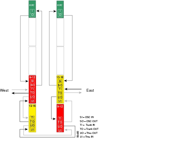
Figure 8-23 shows how the 4-channel mux/demux modules are cabled for node 5 in the line card protected hubbed ring shown in Figure 8-3.
Figure 8-23 Add/Drop Mux/Demux Module Cabling with OSC for Node 5 in Line Card Protected Hubbed Ring
Patch Connections
Node5#configure terminalNode5(config)#patch thru 0/3 thru 1/2Node5(config)#patch wave 0 oscfilter 0/3Node5(config)#patch wave 1 oscfilter 1/2Transparent Interfaces in Slot 9
Node5(config)#interface transparent 9/0/0Node5(config-if)#encapsulation gigabitethernetNode5(config-if)#monitor enableNode5(config-if)#exit<Configure the remaining transparent interfaces in the slot>Transparent Interfaces in Slot 11
Node5(config)#interface transparent 11/0/0Node5(config-if)#encapsulation gigabitethernetNode5(config-if)#monitor enableNode5(config-if)#exit<Configure the remaining transparent interfaces in the slot>OSC Interfaces
Node5(config)#interface wave 0Node5(config-if)#no shutdownNode5(config-if)#exitNode5(config)#interface wave 1Node5(config-if)#no shutdownNode5(config-if)#exitAPS
Use the following for configuring y-cable protection.
Node5(config)#redundancyNode5(config-red)#associate group channel13Node5(config-red-aps)#aps working transparent 9/0/0Node5(config-red-aps)#aps protection transparent 11/0/0Node5(config-red-aps)#aps y-cableNode5(config-red-aps)#aps revertiveNode5(config-red-aps)#aps enableNode5(config-red-aps)#exitNode5(config-red)#associate group channel14Node5(config-red-aps)#aps working transparent 9/1/0Node5(config-red-aps)#aps protection transparent 11/1/0Node5(config-red-aps)#aps y-cableNode5(config-red-aps)#aps revertiveNode5(config-red-aps)#aps enableNode5(config-red-aps)#exitNode5(config-red)#associate group channel15Node5(config-red-aps)#aps working transparent 9/2/0Node5(config-red-aps)#aps protection transparent 11/2/0Node5(config-red-aps)#aps y-cableNode5(config-red-aps)#aps revertiveNode5(config-red-aps)#aps enableNode5(config-red-aps)#exitNode5(config-red)#associate group channel16Node5(config-red-aps)#aps working transparent 9/3/0Node5(config-red-aps)#aps protection transparent 11/3/0Node5(config-red-aps)#aps y-cableNode5(config-red-aps)#aps revertiveNode5(config-red-aps)#aps enableNode5(config-red-aps)#endNode5#copy system:running-config nvram:startup-configConfiguring a Meshed Ring with Splitter Protection and OSC
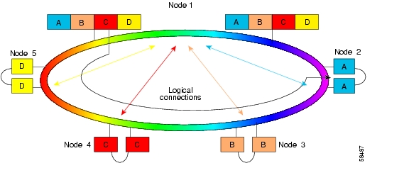
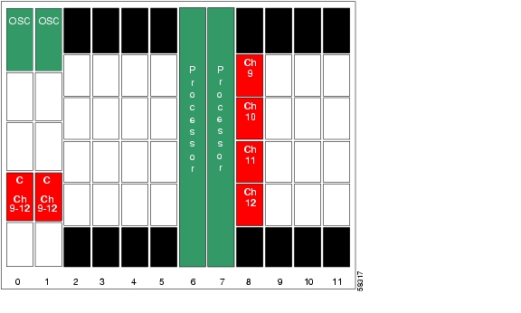
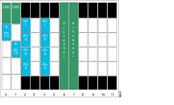
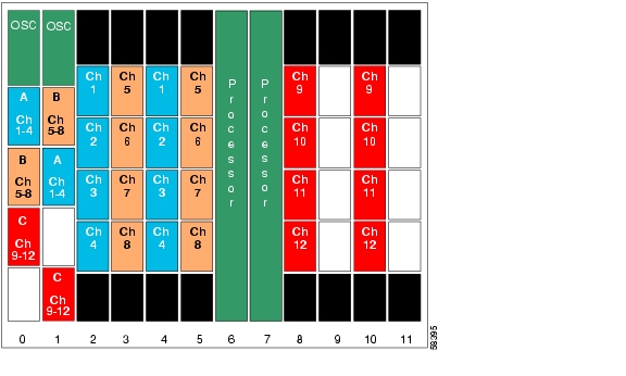
Figure 8-24 shows an example topology of a four-node meshed ring with splitter protection and OSC support. Node 1 supports bands A, B, and C (channels 1 through 12). Node 2 adds and drops band A, node 3 adds and drops band B and band D, and node 4 adds and drops band C and band D. The transponders carry Gigabit Ethernet traffic.
Figure 8-24 Channel Plan for Meshed Ring
Node 1
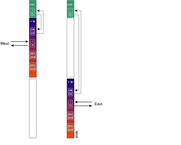
Figure 8-25 shows the shelf configuration for node 1 in the splitter protected meshed ring shown in Figure 8-24. Splitter protected line card motherboards are used to couple the signal to the add/drop mux/demux modules in both west and east mux/demux slots.
Figure 8-25 Shelf Configuration for Node 1 in Splitter Protected Meshed Ring
Figure 8-26 shows how the 4-channel mux/demux modules are cabled for node 1 in the splitter protected meshed ring shown in Figure 8-24.
Figure 8-26 Add/Drop Mux/Demux Module Cabling with OSC for Node 1 in Splitter Protected Meshed Ring
Patch Connections
Node1#configure terminalNode1(config)#patch thru 0/0 wdm 0/1Node1(config)#patch thru 0/1 wdm 0/2Node1(config)#patch thru 0/2 thru 1/0Node1(config)#patch wdm 1/0 thru 1/1Node1(config)#patch wdm 1/1 thru 1/2Node1(config)#patch wave 0 oscfilter 0/0Node1(config)#patch wave 1 oscfilter 1/2Transparent Interfaces in Slot 2
Node1(config)#interface transparent 2/0/0Node1(config-if)#encapsulation gigabitethernetNode1(config-if)#monitor enableNode1(config-if)#exit<Configure the remaining transparent interfaces in the slot>Transparent Interfaces in Slot 5
Node1(config)#interface transparent 5/0/0Node1(config-if)#encapsulation gigabitethernetNode1(config-if)#monitor enableNode1(config-if)#exit<Configure the remaining transparent interfaces in the slot>Transparent Interfaces in Slot 8
Node1(config)#interface transparent 8/0/0Node1(config-if)#encapsulation gigabitethernetNode1(config-if)#monitor enableNode1(config-if)#exit<Configure the remaining transparent interfaces in the slot>OSC Interfaces
Node1(config)#interface wave 0Node1(config-if)#no shutdownNode1(config-if)#exitNode1(config)#interface wave 1Node1(config-if)#no shutdownNode1(config-if)#exitAPS
Node1(config)#redundancyNode1(config-red)#associate group channel1Node1(config-red-aps)#aps working wavepatch 2/0/1Node1(config-red-aps)#aps protection wavepatch 2/0/0Node1(config-red-aps)#aps enableNode1(config-red-aps)#exitNode1(config-red)#associate group channel2Node1(config-red-aps)#aps working wavepatch 2/1/1Node1(config-red-aps)#aps protection wavepatch 2/1/0Node1(config-red-aps)#aps enableNode1(config-red-aps)#exitNode1(config-red)#associate group channel3Node1(config-red-aps)#aps working wavepatch 2/2/1Node1(config-red-aps)#aps protection wavepatch 2/2/0Node1(config-red-aps)#aps enableNode1(config-red-aps)#exitNode1(config-red)#associate group channel4Node1(config-red-aps)#aps working wavepatch 2/3/1Node1(config-red-aps)#aps protection wavepatch 2/3/0Node1(config-red-aps)#aps enableNode1(config-red-aps)#exitNode1(config-red)#associate group channel5Node1(config-red-aps)#aps working wavepatch 5/0/1Node1(config-red-aps)#aps protection wavepatch 5/0/0Node1(config-red-aps)#aps enableNode1(config-red-aps)#exitNode1(config-red)#associate group channel6Node1(config-red-aps)#aps working wavepatch 5/1/1Node1(config-red-aps)#aps protection wavepatch 5/1/0Node1(config-red-aps)#aps enableNode1(config-red-aps)#exitNode1(config-red)#associate group channel7Node1(config-red-aps)#aps working wavepatch 5/2/1Node1(config-red-aps)#aps protection wavepatch 5/2/0Node1(config-red-aps)#aps enableNode1(config-red-aps)#exitNode1(config-red)#associate group channel8Node1(config-red-aps)#aps working wavepatch 5/3/1Node1(config-red-aps)#aps protection wavepatch 5/3/0Node1(config-red-aps)#aps enableNode1(config-red-aps)#exitNode1(config-red)#associate group channel9Node1(config-red-aps)#aps working wavepatch 8/0/0Node1(config-red-aps)#aps protection wavepatch 8/0/1Node1(config-red-aps)#aps enableNode1(config-red-aps)#exitNode1(config-red)#associate group channel10Node1(config-red-aps)#aps working wavepatch 8/1/0Node1(config-red-aps)#aps protection wavepatch 8/1/1Node1(config-red-aps)#aps enableNode1(config-red-aps)#exitNode1(config-red)#associate group channel11Node1(config-red-aps)#aps working wavepatch 8/2/0Node1(config-red-aps)#aps protection wavepatch 8/2/1Node1(config-red-aps)#aps enableNode1(config-red-aps)#exitNode1(config-red)#associate group channel12Node1(config-red-aps)#aps working wavepatch 8/3/0Node1(config-red-aps)#aps protection wavepatch 8/3/1Node1(config-red-aps)#aps enableNode1(config-red-aps)#endNode1#copy system:running-config nvram:startup-configNode 2
Figure 8-27 shows the shelf configuration for node 2 in the splitter protected meshed ring shown in Figure 8-24. Slot 2 uses the splitter protected line card motherboard, which couples the signal to the add/drop mux/demux modules in both west and east mux/demux slots.
Figure 8-27 Shelf Configuration for Node 2 in Splitter Protected Meshed Ring
Figure 8-28 shows how the 4-channel mux/demux modules are cabled for node 2 in the splitter protected meshed ring shown in Figure 8-24.
Figure 8-28 Add/Drop Mux/Demux Module Cabling with OSC for Node 2 in Splitter Protected Meshed Ring
Patch Connections
Node2#configure terminalNode2(config)#patch thru 0/0 thru 1/0Node2(config)#patch wave 0 oscfilter 0/0Node2(config)#patch wave 1 oscfilter 1/0Transparent Interfaces in Slot 2
Node2(config)#interface transparent 2/0/0Node2(config-if)#encapsulation gigabitethernetNode2(config-if)#monitor enableNode2(config-if)#exit<Configure the remaining transparent interfaces in the slot>OSC Interfaces
Node2(config)#interface wave 0Node2(config-if)#no shutdownNode2(config-if)#exitNode2(config)#interface wave 1Node2(config-if)#no shutdownNode2(config-if)#exitAPS
Node2(config)#redundancyNode2(config-red)#associate group channel1Node2(config-red-aps)#aps working wavepatch 2/0/0Node2(config-red-aps)#aps protection wavepatch 2/0/1Node2(config-red-aps)#aps enableNode2(config-red-aps)#exitNode2(config-red)#associate group channel2Node2(config-red-aps)#aps working wavepatch 2/1/0Node2(config-red-aps)#aps protection wavepatch 2/1/1Node2(config-red-aps)#aps enableNode2(config-red-aps)#exitNode2(config-red)#associate group channel3Node2(config-red-aps)#aps working wavepatch 2/2/0Node2(config-red-aps)#aps protection wavepatch 2/2/1Node2(config-red-aps)#aps enableNode2(config-red-aps)#exitNode2(config-red)#associate group channel4Node2(config-red-aps)#aps working wavepatch 2/3/0Node2(config-red-aps)#aps protection wavepatch 2/3/1Node2(config-red-aps)#aps enableNode2(config-red-aps)#endNode2#copy system:running-config nvram:startup-configNode 3
Figure 8-29 shows the shelf configuration for node 3 in the splitter protected meshed ring shown in Figure 8-24. Slots 5 and 11 use splitter protected line card motherboards, which couple the signal to the add/drop mux/demux modules in both west and east mux/demux slots.
Figure 8-29 Shelf Configuration for Node 3 in Splitter Protected Meshed Ring
Figure 8-30 shows how the 4-channel mux/demux modules are cabled for node 3 in the splitter protected meshed ring shown in Figure 8-24.
Figure 8-30 Add/Drop Mux/Demux Module Cabling with OSC for Node 3 in Splitter Protected Meshed Ring
Patch Connections
Node3#configure terminalNode3(config)#patch wdm 0/1 thru 0/3Node3(config)#patch thru 0/1 thru 1/3Node3(config)#patch wdm 1/3 thru 1/1Node3(config)#patch wave 0 oscfilter 0/3Node3(config)#patch wave 1 oscfilter 1/1Transparent Interfaces in Slot 5
Node3(config)#interface transparent 5/0/0Node3(config-if)#encapsulation gigabitethernetNode3(config-if)#monitor enableNode3(config-if)#exit<Configure the remaining transparent interfaces in the slot>Transparent Interfaces in Slot 11
Node3(config)#interface transparent 11/0/0Node3(config-if)#encapsulation gigabitethernetNode3(config-if)#monitor enableNode3(config-if)#exit<Configure the remaining transparent interfaces in the slot>OSC Interfaces
Node3(config)#interface wave 0Node3(config-if)#no shutdownNode3(config-if)#exitNode3(config)#interface wave 1Node3(config-if)#no shutdownNode3(config-if)#exitAPS
Node3(config)#redundancyNode3(config-red)#associate group channel5Node3(config-red-aps)#aps working wavepatch 5/0/0Node3(config-red-aps)#aps protection wavepatch 5/0/1Node3(config-red-aps)#aps enableNode3(config-red-aps)#exitNode3(config-red)#associate group channel6Node3(config-red-aps)#aps working wavepatch 5/1/0Node3(config-red-aps)#aps protection wavepatch 5/1/1Node3(config-red-aps)#aps enableNode3(config-red-aps)#exitNode3(config-red)#associate group channel7Node3(config-red-aps)#aps working wavepatch 5/2/0Node3(config-red-aps)#aps protection wavepatch 5/2/1Node3(config-red-aps)#aps enableNode3(config-red-aps)#exitNode3(config-red)#associate group channel8Node3(config-red-aps)#aps working wavepatch 5/3/0Node3(config-red-aps)#aps protection wavepatch 5/3/1Node3(config-red-aps)#aps enableNode3(config-red-aps)#exitNode3(config-red)#associate group channel13Node3(config-red-aps)#aps working wavepatch 11/0/1Node3(config-red-aps)#aps protection wavepatch 11/0/0Node3(config-red-aps)#aps enableNode3(config-red-aps)#exitNode3(config-red)#associate group channel14Node3(config-red-aps)#aps working wavepatch 11/1/1Node3(config-red-aps)#aps protection wavepatch 11/1/0Node3(config-red-aps)#aps enableNode3(config-red-aps)#exitNNode3(config-red)#associate group channel15Node3(config-red-aps)#aps working wavepatch 11/2/1Node3(config-red-aps)#aps protection wavepatch 11/2/0Node3(config-red-aps)#aps enableNode3(config-red-aps)#exitNode3(config-red)#associate group channel16Node3(config-red-aps)#aps working wavepatch 11/3/1Node3(config-red-aps)#aps protection wavepatch 11/3/0Node3(config-red-aps)#aps enableNode3(config-red-aps)#endNode3#copy system:running-config nvram:startup-configNode 4
Figure 8-31 shows the shelf configuration for node 4 in the splitter protected meshed ring shown in Figure 8-24. Slots 8 and 11 use the splitter protected line card motherboards, which couple the signal to the add/drop mux/demux modules in both the west and east mux/demux slots.
Figure 8-31 Module Installation Configuration for Node 4
Figure 8-32 shows how the 4-channel mux/demux modules are cabled for node 4 in the splitter protected meshed ring shown in Figure 8-24.
Figure 8-32 Add/Drop Mux/Demux Module Cabling with OSC for Node 4 in Splitter Protected Meshed Ring
Patch Connections
Node4#configure terminalNode4(config)#patch thru 0/2 wdm 0/3Node4(config)#patch thru 0/3 thru 1/2Node4(config)#patch wdm 1/2 thru 1/3Node4(config)#patch wave 0 oscfilter 0/2Node4(config)#patch wave 1 oscfilter 1/3Transparent Interfaces in Slot 8
Node4(config)#interface transparent 8/0/0Node4(config-if)#encapsulation gigabitethernetNode4(config-if)#monitor enableNode4(config-if)#exit<Configure the remaining transparent interfaces in the slot>Transparent Interfaces in Slot 11
Node4(config)#interface transparent 11/0/0Node4(config-if)#encapsulation gigabitethernetNode4(config-if)#monitor enableNode4(config-if)#exit<Configure the remaining transparent interfaces in the slot>OSC Interfaces
Node4(config)#interface wave 0Node4(config-if)#no shutdownNode4(config-if)#exitNode4(config)#interface wave 1Node4(config-if)#no shutdownNode4(config-if)#exitAPS
Node4(config)#redundancyNode4(config-red)#associate group channel9Node4(config-red-aps)#aps working wavepatch 8/0/1Node4(config-red-aps)#aps protection wavepatch 8/0/0Node4(config-red-aps)#aps enableNode4(config-red-aps)#exitNode4(config-red)#associate group channel10Node4(config-red-aps)#aps working wavepatch 8/1/1Node4(config-red-aps)#aps protection wavepatch 8/1/0Node4(config-red-aps)#aps enableNode4(config-red-aps)#exitNode4(config-red)#associate group channel11Node4(config-red-aps)#aps working wavepatch 8/2/1Node4(config-red-aps)#aps protection wavepatch 8/2/0Node4(config-red-aps)#aps enableNode4(config-red-aps)#exitNode4(config-red)#associate group channel12Node4(config-red-aps)#aps working wavepatch 8/3/1Node4(config-red-aps)#aps protection wavepatch 8/3/0Node4(config-red-aps)#aps enableNode4(config-red-aps)#exitNode4(config-red)#associate group channel13Node4(config-red-aps)#aps working wavepatch 11/0/0Node4(config-red-aps)#aps protection wavepatch 11/0/1Node4(config-red-aps)#aps enableNode4(config-red-aps)#exitNode4(config-red)#associate group channel14Node4(config-red-aps)#aps working wavepatch 11/1/0Node4(config-red-aps)#aps protection wavepatch 11/1/1Node4(config-red-aps)#aps enableNode4(config-red-aps)#exitNode4(config-red)#associate group channel15Node4(config-red-aps)#aps working wavepatch 11/2/0Node4(config-red-aps)#aps protection wavepatch 11/2/1Node4(config-red-aps)#aps enableNode4(config-red-aps)#exitNode4(config-red)#associate group channel16Node4(config-red-aps)#aps working wavepatch 11/3/0Node4(config-red-aps)#aps protection wavepatch 11/3/1Node4(config-red-aps)#aps enableNode4(config-red-aps)#endNode4#copy system:running-config nvram:startup-configConfiguring a Splitter Protected Meshed Ring with Unprotected Channels and OSC
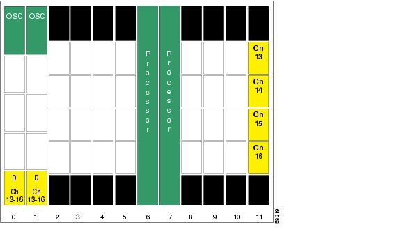
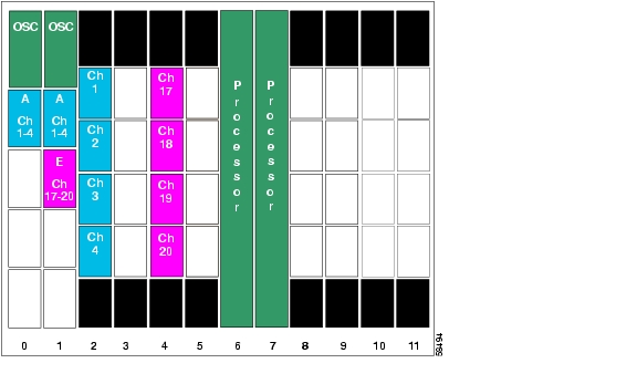
Figure 8-33 shows an example topology of a four-node meshed ring with splitter protection and OSC support. Node 1 supports bands A, B, and C (channels 1-12). Node 2 adds and drops band A (channels 1-4) and unprotected band E (channels 17-20). Node 3 adds and drops band B (channels 5-8), band D (channels 13-16), and unprotected band E (channels 17-20). Node 4 adds and drops band C (channels 9-12) and band D (channels 13-16). The transponders carry Gigabit Ethernet traffic.
Figure 8-33 Overview of Meshed Ring Topology with Splitter Protection
Node 1
The configuration for node 1 is the same as described in the "Node 1" section.
Node 2
Figure 8-34 shows the shelf configuration for node 2 in the splitter protected meshed ring with unprotected channels shown in Figure 8-33. Slot 2 uses the splitter protected line card motherboard, which couples the signal to the add/drop mux/demux modules in subcard 0 of both west and east mux/demux slots. Slot 4, which supports the unprotected channels, uses an east line card motherboard.
Figure 8-34 Shelf Configuration for Node 2 in Splitter Protected Meshed Ring with Unprotected Channels
Figure 8-35 shows how the 4-channel mux/demux modules are cabled for node 2 in the splitter protected meshed ring with unprotected channel shown in Figure 8-33.
Figure 8-35 Add/Drop Mux/Demux Module Cabling for Node 2 in Splitter Protected Meshed Ring with Unprotected Channels
Patch Connections
Node2#configure terminalNode2(config)#patch thru 0/0 thru 1/1Node2(config)#patch wdm 1/1 thru 1/0Node2(config)#patch wave 0 oscfilter 0/0Node2(config)#patch wave 1 oscfilter 1/0Transparent Interfaces in Slot 2
Node2(config)#interface transparent 2/0/0Node2(config-if)#encapsulation gigabitethernetNode2(config-if)#monitor enableNode2(config-if)#exit<Configure the remaining transparent interfaces in the slot>Transparent Interfaces in Slot 4
Node2(config)#interface transparent 4/0/0Node2(config-if)#encapsulation gigabitethernetNode2(config-if)#monitor enableNode2(config-if)#exit<Configure the remaining transparent interfaces in the slot>OSC Interfaces
Node2(config)#interface wave 0Node2(config-if)#no shutdownNode2(config-if)#exitNode2(config)#interface wave 1Node2(config-if)#no shutdownNode2(config-if)#exitAPS
Node2(config)#redundancyNode2(config-red)#associate group channel1Node2(config-red-aps)#aps working wavepatch 2/0/0Node2(config-red-aps)#aps protection wavepatch 2/0/1Node2(config-red-aps)#aps enableNode2(config-red-aps)#exitNode2(config-red)#associate group channel2Node2(config-red-aps)#aps working wavepatch 2/1/0Node2(config-red-aps)#aps protection wavepatch 2/1/1Node2(config-red-aps)#aps enableNode2(config-red-aps)#exitNode2(config-red)#associate group channel3Node2(config-red-aps)#aps working wavepatch 2/2/0Node2(config-red-aps)#aps protection wavepatch 2/2/1Node2(config-red-aps)#aps enableNode2(config-red-aps)#exitNode2(config-red)#associate group channel4Node2(config-red-aps)#aps working wavepatch 2/3/0Node2(config-red-aps)#aps protection wavepatch 2/3/1Node2(config-red-aps)#aps enableNode2(config-red-aps)#endNode2#copy system:running-config nvram:startup-configNode 3
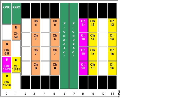
Figure 8-36 shows the shelf configuration for node 3 in the splitter protected meshed ring with unprotected channels shown in Figure 8-33. Slot 5 and slot 11 use splitter protected line card motherboards, which couple the signal to the add/drop mux/demux modules in subcard 1 and subcard 3, respectively, of both west and east mux/demux slots. Slot 8, which supports the unprotected channels, uses a west line card motherboard.
Figure 8-36 Shelf Configuration for Node 3 in Splitter Protected Meshed Ring with Unprotected Channels
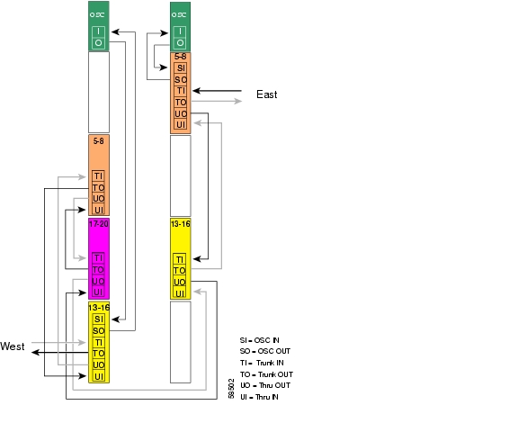
Figure 8-37 shows how the 4-channel mux/demux modules are cabled for node 3 in the splitter protected meshed ring with unprotected channels shown in Figure 8-33.
Figure 8-37 Add/Drop Mux/Demux Module Cabling for Node 3 in Splitter Protected Meshed Ring with Unprotected Channels
Patch Connections
Node3#configure terminalNode3(config)#patch thru 0/3 wdm 0/1Node3(config)#patch thru 0/1 wdm 0/2Node3(config)#patch thru 0/2 thru 1/3Node3(config)#patch wdm 1/3 thru 1/1Node3(config)#patch wave 0 oscfilter 0/3Node3(config)#patch wave 1 oscfilter 1/1Transparent Interfaces in Slot 5
Node3(config)#interface transparent 5/0/0Node3(config-if)#encapsulation gigabitethernetNode3(config-if)#monitor enableNode3(config-if)#exit<Configure the remaining transparent interfaces in the slot>Transparent Interfaces in Slot 8
Node3(config)#interface transparent 8/0/0Node3(config-if)#encapsulation gigabitethernetNode3(config-if)#monitor enableNode3(config-if)#exit<Configure the remaining transparent interfaces in the slot>Transparent Interfaces in Slot 11
Node3(config)#interface transparent 11/0/0Node3(config-if)#encapsulation gigabitethernetNode3(config-if)#monitor enableNode3(config-if)#exit<Configure the remaining transparent interfaces in the slot>OSC Interfaces
Node3(config)#interface wave 0Node3(config-if)#no shutdownNode3(config-if)#exitNode3(config)#interface wave 1Node3(config-if)#no shutdownNode3(config-if)#exitAPS
Node3(config)#redundancyNode3(config-red)#associate group channel5Node3(config-red-aps)#aps working wavepatch 5/0/0Node3(config-red-aps)#aps protection wavepatch 5/0/1Node3(config-red-aps)#aps enableNode3(config-red-aps)#exitNode3(config-red)#associate group channel6Node3(config-red-aps)#aps working wavepatch 5/1/0Node3(config-red-aps)#aps protection wavepatch 5/1/1Node3(config-red-aps)#aps enableNode3(config-red-aps)#exitNode3(config-red)#associate group channel7Node3(config-red-aps)#aps working wavepatch 5/2/0Node3(config-red-aps)#aps protection wavepatch 5/2/1Node3(config-red-aps)#aps enableNode3(config-red-aps)#exitNode3(config-red)#associate group channel8Node3(config-red-aps)#aps working wavepatch 5/3/0Node3(config-red-aps)#aps protection wavepatch 5/3/1Node3(config-red-aps)#aps enableNode3(config-red-aps)#exitNode3(config-red)#associate group channel13Node3(config-red-aps)#aps working wavepatch 11/0/1Node3(config-red-aps)#aps protection wavepatch 11/0/0Node3(config-red-aps)#aps enableNode3(config-red-aps)#exitNode3(config-red)#associate group channel14Node3(config-red-aps)#aps working wavepatch 11/1/1Node3(config-red-aps)#aps protection wavepatch 11/1/0Node3(config-red-aps)#aps enableNode3(config-red-aps)#exitNNode3(config-red)#associate group channel15Node3(config-red-aps)#aps working wavepatch 11/2/1Node3(config-red-aps)#aps protection wavepatch 11/2/0Node3(config-red-aps)#aps enableNode3(config-red-aps)#exitNode3(config-red)#associate group channel16Node3(config-red-aps)#aps working wavepatch 11/3/1Node3(config-red-aps)#aps protection wavepatch 11/3/0Node3(config-red-aps)#aps enableNode3(config-red-aps)#endNode3#copy system:running-config nvram:startup-configNode 4
The configuration for node 4 is the same as described in the "Node 4" section.
Configuring a Meshed Ring with Line Card Protection and OSC
Line card protection requires different shelf and CLI configuration from splitter protection. The following sections describe an example based on the meshed ring topology shown in Figure 8-24.
Node 1
Figure 8-38 shows the shelf configuration for node 1 using line card protection in the example meshed ring shown in Figure 8-24. Slots 2, 5, and 8 use west line card motherboards, corresponding to the add/drop mux/demux modules in the west mux/demux slot; slots 3, 4, and 10 use east line card motherboards, corresponding to the add/drop mux/demux modules in the east mux/demux slot.
Figure 8-38 Shelf Configuration for Node 1 in Line Card Protected Meshed Ring
Figure 8-39 shows how the 4-channel mux/demux modules are cabled for node 1 in the line card protected meshed ring shown in Figure 8-24.
Figure 8-39 Add/Drop Mux/Demux Module Cabling with OSC for Node 1 in Line Card Protected Meshed Ring
Patch Connections
Node1#configure terminalNode1(config)#patch thru 0/0 wdm 0/1Node1(config)#patch thru 0/1 wdm 0/2Node1(config)#patch thru 0/2 thru 1/1Node1(config)#patch wdm 1/1 thru 1/0Node1(config)#patch wdm 1/0 thru 1/3Node1(config)#patch wave 0 oscfilter 0/0Node1(config)#patch wave 1 oscfilter 1/3Transparent Interfaces
Node1(config)#interface transparent 2/0/0Node1(config-if)#encapsulation gigabitethernetNode1(config-if)#monitor enableNode1(config-if)#exit<Configure the remaining transparent interfaces in the shelf>OSC Interfaces
Node1(config)#interface wave 0Node1(config-if)#no shutdownNode1(config-if)#exitNode1(config)#interface wave 1Node1(config-if)#no shutdownNode1(config-if)#exitAPS
Use the following for configuring y-cable protection.
Node1(config)#redundancyNode1(config-red)#associate group channel1Node1(config-red-aps)#aps working transparent 4/0/0Node1(config-red-aps)#aps protection transparent 2/0/0Node1(config-red-aps)#aps y-cableNode1(config-red-aps)#aps revertiveNode1(config-red-aps)#aps enableNode1(config-red-aps)#exitNode1(config-red)#associate group channel2Node1(config-red-aps)#aps working transparent 4/1/0Node1(config-red-aps)#aps protection transparent 2/1/0Node1(config-red-aps)#aps y-cableNode1(config-red-aps)#aps revertiveNode1(config-red-aps)#aps enableNode1(config-red-aps)#exitNode1(config-red)#associate group channel3Node1(config-red-aps)#aps working transparent 4/2/0Node1(config-red-aps)#aps protection transparent 2/2/0Node1(config-red-aps)#aps y-cableNode1(config-red-aps)#aps revertiveNode1(config-red-aps)#aps enableNode1(config-red-aps)#exitNode1(config-red)#associate group channel4Node1(config-red-aps)#aps working transparent 4/3/0Node1(config-red-aps)#aps protection transparent 2/3/0Node1(config-red-aps)#aps y-cableNode1(config-red-aps)#aps revertiveNode1(config-red-aps)#aps enableNode1(config-red-aps)#exitNode1(config-red)#associate group channel5Node1(config-red-aps)#aps working transparent 5/0/0Node1(config-red-aps)#aps protection transparent 3/0/0Node1(config-red-aps)#aps y-cableNode1(config-red-aps)#aps revertiveNode1(config-red-aps)#aps enableNode1(config-red-aps)#exitNode1(config-red)#associate group channel6Node1(config-red-aps)#aps working transparent 5/1/0Node1(config-red-aps)#aps protection transparent 3/1/0Node1(config-red-aps)#aps y-cableNode1(config-red-aps)#aps revertiveNode1(config-red-aps)#aps enableNode1(config-red-aps)#exitNode1(config-red)#associate group channel7Node1(config-red-aps)#aps working transparent 5/2/0Node1(config-red-aps)#aps protection transparent 3/2/0Node1(config-red-aps)#aps y-cableNode1(config-red-aps)#aps revertiveNode1(config-red-aps)#aps enableNode1(config-red-aps)#exitNode1(config-red)#associate group channel8Node1(config-red-aps)#aps working transparent 5/3/0Node1(config-red-aps)#aps protection transparent 3/3/0Node1(config-red-aps)#aps y-cableNode1(config-red-aps)#aps revertiveNode1(config-red-aps)#aps enableNode1(config-red-aps)#exitNode1(config-red)#associate group channel9Node1(config-red-aps)#aps working transparent 8/0/0Node1(config-red-aps)#aps protection transparent 11/0/0Node1(config-red-aps)#aps y-cableNode1(config-red-aps)#aps revertiveNode1(config-red-aps)#aps enableNode1(config-red-aps)#exitNode1(config-red)#associate group channel10Node1(config-red-aps)#aps working transparent 8/1/0Node1(config-red-aps)#aps protection transparent 11/1/0Node1(config-red-aps)#aps y-cableNode1(config-red-aps)#aps revertiveNode1(config-red-aps)#aps enableNode1(config-red-aps)#exitNode1(config-red)#associate group channel11Node1(config-red-aps)#aps working transparent 8/2/0Node1(config-red-aps)#aps protection transparent 11/2/0Node1(config-red-aps)#aps y-cableNode1(config-red-aps)#aps revertiveNode1(config-red-aps)#aps enableNode1(config-red-aps)#exitNode1(config-red)#associate group channel12Node1(config-red-aps)#aps working transparent 8/3/0Node1(config-red-aps)#aps protection transparent 11/3/0Node1(config-red-aps)#aps y-cableNode1(config-red-aps)#aps revertiveNode1(config-red-aps)#aps enableNode1(config-red-aps)#endNode1#copy system:running-config nvram:startup-configNode 2
Figure 8-40 shows the shelf configuration for node 2 in the line card protected meshed ring shown in Figure 8-24. Slot 2 uses the west line card motherboard, corresponding to the add/drop mux/demux module in the west mux/demux slot; slot 4 uses the east line card motherboard, corresponding to the add/drop mux/demux module in the east mux/demux slot.
Figure 8-40 Shelf Configuration for Node 2 in Line Card Protected Meshed Ring
Figure 8-41 shows how the 4-channel mux/demux modules are cabled for node 2 in the line card protected meshed ring shown in Figure 8-24.
Figure 8-41 Add/Drop Mux/Demux Module Cabling with OSC for Node 2 in Line Card Protected Meshed Ring
Patch Connections
Node2#configure terminalNode2(config)#patch thru 0/0 thru 1/1Node2(config)#patch wave 0 oscfilter 0/0Node2(config)#patch wave 1 oscfilter 1/1Transparent Interfaces in Slot 2
Node2(config)#interface transparent 2/0/0Node2(config-if)#encapsulation gigabitethernetNode2(config-if)#monitor enableNode2(config-if)#exit<Configure the remaining transparent interfaces in the slot>Transparent Interfaces in Slot 4
Node2(config)#interface transparent 4/0/0Node2(config-if)#encapsulation gigabitethernetNode2(config-if)#monitor enableNode2(config-if)#exit<Configure the remaining transparent interfaces in the slot>OSC Interfaces
Node2(config)#interface wave 0Node2(config-if)#no shutdownNode2(config-if)#exitNode2(config)#interface wave 1Node2(config-if)#no shutdownNode2(config-if)#exitAPS
Use the following for configuring y-cable protection.
Node2(config)#redundancyNode2(config-red)#associate group channel1Node2(config-red-aps)#aps working transparent 2/0/0Node2(config-red-aps)#aps protection transparent 4/0/0Node2(config-red-aps)#aps y-cableNode2(config-red-aps)#aps revertiveNode2(config-red-aps)#aps enableNode2(config-red-aps)#exitNode2(config-red)#associate group channel2Node2(config-red-aps)#aps working transparent 2/1/0Node2(config-red-aps)#aps protection transparent 4/1/0Node2(config-red-aps)#aps y-cableNode2(config-red-aps)#aps revertiveNode2(config-red-aps)#aps enableNode2(config-red-aps)#exitNode2(config-red)#associate group channel3Node2(config-red-aps)#aps working transparent 2/2/0Node2(config-red-aps)#aps protection transparent 4/2/0Node2(config-red-aps)#aps y-cableNode2(config-red-aps)#aps revertiveNode2(config-red-aps)#aps enableNode2(config-red-aps)#exitNode2(config-red)#associate group channel4Node2(config-red-aps)#aps working transparent 2/3/0Node2(config-red-aps)#aps protection transparent 4/3/0Node2(config-red-aps)#aps y-cableNode2(config-red-aps)#aps revertiveNode2(config-red-aps)#aps enableNode2(config-red-aps)#endNode2#copy system:running-config nvram:startup-configNode 3
Figure 8-42 shows the shelf configuration for node 3 in the line card protected meshed ring shown in Figure 8-24. Slots 5 and 11 use the west line card motherboards, corresponding to the add/drop mux/demux modules in the west mux/demux slot; slots 3 and 9 use the east line card motherboards, corresponding to the add/drop mux/demux modules in the east mux/demux slot.
Figure 8-42 Shelf Configuration for Node 3 in Line Card Protected Meshed Ring
Figure 8-43 shows how the 4-channel mux/demux modules are cabled for the line card protected meshed ring shown in Figure 8-24.
Figure 8-43 Add/Drop Mux/Demux Module Cabling with OSC for Node 3 in Line Card Protected Meshed Ring
Patch Connections
Node3#configure terminalNode3(config)#patch thru 0/1 wdm 0/3Node3(config)#patch thru 0/3 thru 1/0Node3(config)#patch wdm 1/0 thru 1/2Node3(config)#patch wave 0 oscfilter 0/3Node3(config)#patch wave 1 oscfilter 1/0Transparent Interfaces in Slot 3
Node3(config)#interface transparent 3/0/0Node3(config-if)#encapsulation gigabitethernetNode3(config-if)#monitor enableNode3(config-if)#exit<Configure the remaining transparent interfaces in the slot>Transparent Interfaces in Slot 5
Node3(config)#interface transparent 5/0/0Node3(config-if)#encapsulation gigabitethernetNode3(config-if)#monitor enableNode3(config-if)#exit<Configure the remaining transparent interfaces in the slot>Transparent Interfaces in Slot 9
Node3(config)#interface transparent 9/0/0Node3(config-if)#encapsulation gigabitethernetNode3(config-if)#monitor enableNode3(config-if)#exit<Configure the remaining transparent interfaces in the slot>Transparent Interfaces in Slot 11
Node3(config)#interface transparent 11/0/0Node3(config-if)#encapsulation gigabitethernetNode3(config-if)#monitor enableNode3(config-if)#exit<Configure the remaining transparent interfaces in the slot>OSC Interfaces
Node3(config)#interface wave 0Node3(config-if)#no shutdownNode3(config-if)#exitNode3(config)#interface wave 1Node3(config-if)#no shutdownNode3(config-if)#exitAPS
Use the following for configuring y-cable protection.
Node3(config)#redundancyNode3(config-red)#associate group channel5Node3(config-red-aps)#aps working transparent 3/0/0Node3(config-red-aps)#aps protection transparent 5/0/0Node3(config-red-aps)#aps y-cableNode3(config-red-aps)#aps revertiveNode3(config-red-aps)#aps enableNode3(config-red-aps)#exitNode3(config-red)#associate group channel6Node3(config-red-aps)#aps working transparent 3/1/0Node3(config-red-aps)#aps protection transparent 5/1/0Node3(config-red-aps)#aps y-cableNode3(config-red-aps)#aps revertiveNode3(config-red-aps)#aps enableNode3(config-red-aps)#exitNode3(config-red)#associate group channel7Node3(config-red-aps)#aps working transparent 3/2/0Node3(config-red-aps)#aps protection transparent 5/2/0Node3(config-red-aps)#aps y-cableNode3(config-red-aps)#aps revertiveNode3(config-red-aps)#aps enableNode3(config-red-aps)#exitNode3(config-red)#associate group channel8Node3(config-red-aps)#aps working transparent 3/3/0Node3(config-red-aps)#aps protection transparent 5/3/0Node3(config-red-aps)#aps y-cableNode3(config-red-aps)#aps revertiveNode3(config-red-aps)#aps enableNode3(config-red-aps)#exitNode3(config-red)#associate group channel13Node3(config-red-aps)#aps working transparent 11/0/0Node3(config-red-aps)#aps protection transparent 9/0/0Node3(config-red-aps)#aps y-cableNode3(config-red-aps)#aps revertiveNode3(config-red-aps)#aps enableNode3(config-red-aps)#exitNode3(config-red)#associate group channel14Node3(config-red-aps)#aps working transparent 11/1/0Node3(config-red-aps)#aps protection transparent 9/1/0Node3(config-red-aps)#aps y-cableNode3(config-red-aps)#aps revertiveNode3(config-red-aps)#aps enableNode3(config-red-aps)#exitNode3(config-red)#associate group channel15Node3(config-red-aps)#aps working transparent 11/2/0Node3(config-red-aps)#aps protection transparent 9/2/0Node3(config-red-aps)#aps y-cableNode3(config-red-aps)#aps revertiveNode3(config-red-aps)#aps enableNode3(config-red-aps)#exitNode3(config-red)#associate group channel16Node3(config-red-aps)#aps working transparent 11/3/0Node3(config-red-aps)#aps protection transparent 9/3/0Node3(config-red-aps)#aps y-cableNode3(config-red-aps)#aps revertiveNode3(config-red-aps)#aps enableNode3(config-red-aps)#endNode3#copy system:running-config nvram:startup-configNode 4
Figure 8-44 shows the shelf configuration for node 4 in the line card protected meshed ring shown in Figure 8-24. Slots 8 and 11 use the west line card motherboards, corresponding to the add/drop mux/demux modules in the west mux/demux slots; slots 9 and 10 use the east line card motherboards, corresponding to the add/drop mux/demux modules in the east mux/demux slots.
Figure 8-44 Shelf Configuration for Node 4 in Line Card Protected Meshed Ring
Figure 8-45 shows how the 4-channel mux/demux modules are cabled for node 4 in the line card protected meshed ring shown in Figure 8-24.
Figure 8-45 Add/Drop Mux/Demux Module Cabling with OSC for Node 4 in Line Card Protected Meshed Ring
Patch Connections
Node4#configure terminalNode4(config)#patch thru 0/2 wdm 0/3Node4(config)#patch thru 0/3 thru 1/3Node4(config)#patch wdm 1/3 thru 1/2Node4(config)#patch wave 0 oscfilter 0/2Node4(config)#patch wave 1 oscfilter 1/2Transparent Interfaces in Slot 8
Node4(config)#interface transparent 8/0/0Node4(config-if)#encapsulation gigabitethernetNode4(config-if)#monitor enableNode4(config-if)#exit<Configure the remaining transparent interfaces in the slot>Transparent Interfaces in Slot 10
Node4(config)#interface transparent 10/0/0Node4(config-if)#encapsulation gigabitethernetNode4(config-if)#monitor enableNode4(config-if)#exit<Configure the remaining transparent interfaces in the slot>OSC Interfaces
Node4(config)#interface wave 0Node4(config-if)#no shutdownNode4(config-if)#exitNode4(config)#interface wave 1Node4(config-if)#no shutdownNode4(config-if)#exitAPS
Use the following for configuring y-cable protection.
Node4(config)#redundancyNode4(config-red)#associate group channel9Node4(config-red-aps)#aps working transparent 10/0/0Node4(config-red-aps)#aps protection transparent 8/0/0Node4(config-red-aps)#aps y-cableNode4(config-red-aps)#aps revertiveNode4(config-red-aps)#aps enableNode4(config-red-aps)#exitNode4(config-red)#associate group channel10Node4(config-red-aps)#aps working transparent 10/1/0Node4(config-red-aps)#aps protection transparent 8/1/0Node4(config-red-aps)#aps y-cableNode4(config-red-aps)#aps revertiveNode4(config-red-aps)#aps enableNode4(config-red-aps)#exitNode4(config-red)#associate group channel11Node4(config-red-aps)#aps working transparent 10/2/0Node4(config-red-aps)#aps protection transparent 8/2/0Node4(config-red-aps)#aps y-cableNode4(config-red-aps)#aps revertiveNode4(config-red-aps)#aps enableNode4(config-red-aps)#exitNode4(config-red)#associate group channel12Node4(config-red-aps)#aps working transparent 10/3/0Node4(config-red-aps)#aps protection transparent 8/3/0Node4(config-red-aps)#aps y-cableNode4(config-red-aps)#aps revertiveNode4(config-red-aps)#aps enableNode4(config-red-aps)#exitNode4(config-red)#associate group channel13Node4(config-red-aps)#aps working transparent 9/0/0Node4(config-red-aps)#aps protection transparent 11/0/0Node4(config-red-aps)#aps y-cableNode4(config-red-aps)#aps revertiveNode4(config-red-aps)#aps enableNode4(config-red-aps)#exitNode4(config-red)#associate group channel13Node4(config-red-aps)#aps working transparent 9/1/0Node4(config-red-aps)#aps protection transparent 11/1/0Node4(config-red-aps)#aps y-cableNode4(config-red-aps)#aps revertiveNode4(config-red-aps)#aps enableNode4(config-red-aps)#exitNode4(config-red)#associate group channel13Node4(config-red-aps)#aps working transparent 9/2/0Node4(config-red-aps)#aps protection transparent 11/2/0Node4(config-red-aps)#aps y-cableNode4(config-red-aps)#aps revertiveNode4(config-red-aps)#aps enableNode4(config-red-aps)#exitNode4(config-red)#associate group channel13Node4(config-red-aps)#aps working transparent 9/3/0Node4(config-red-aps)#aps protection transparent 11/3/0Node4(config-red-aps)#aps y-cableNode4(config-red-aps)#aps revertiveNode4(config-red-aps)#aps enableNode4(config-red-aps)#endNode4#copy system:running-config nvram:startup-configConfiguring a Line Card Protected Meshed Ring with Unprotected Channels and OSC
Line card protection requires different shelf and CLI configuration from splitter protection. The following sections describe an example based on the meshed ring topology shown in Figure 8-33.
Node 1
The configuration for node 1 is the same as described in the "Node 1" section.
Node 2
Figure 8-46 shows the shelf configuration for node 2 in the line card protected meshed ring with unprotected channels shown in Figure 8-33. Channels 1-4 are line card protected using a west line card motherboard in slot 2 and an east line card motherboard in slot 4. Slot 8 uses an east line card motherboard for the unprotected channels.
Figure 8-46 Shelf Configuration for Node 2 in Line Card Protected Meshed Ring with Unprotected Channels
Figure 8-47 shows how the 4-channel mux/demux modules are cabled for node 2 in the line card protected meshed ring with unprotected channels shown in Figure 8-33.
Figure 8-47 Add/Drop Mux/Demux Module Cabling for Node 2 in Line Card Protected Meshed Ring with Unprotected Channels
Patch Connections
Node2#configure terminalNode2(config)#patch thru 0/0 thru 1/2Node2(config)#patch wdm 1/2 thru 1/1Node2(config)#patch wave 0 oscfilter 0/0Node2(config)#patch wave 1 oscfilter 1/1Transparent Interfaces in Slot 2
Node2(config)#interface transparent 2/0/0Node2(config-if)#encapsulation gigabitethernetNode2(config-if)#monitor enableNode2(config-if)#exit<Configure the remaining transparent interfaces in the slot>Transparent Interfaces in Slot 4
Node2(config)#interface transparent 4/0/0Node2(config-if)#encapsulation gigabitethernetNode2(config-if)#monitor enableNode2(config-if)#exit<Configure the remaining transparent interfaces in the slot>Transparent Interfaces in Slot 8
Node2(config)#interface transparent 8/0/0Node2(config-if)#encapsulation gigabitethernetNode2(config-if)#monitor enableNode2(config-if)#exit<Configure the remaining transparent interfaces in the slot>OSC Interfaces
Node2(config)#interface wave 0Node2(config-if)#no shutdownNode2(config-if)#exitNode2(config)#interface wave 1Node2(config-if)#no shutdownNode2(config-if)#exitAPS
Use the following for configuring y-cable protection.
Node2(config)#redundancyNode2(config-red)#associate group channel1Node2(config-red-aps)#aps working transparent 2/0/0Node2(config-red-aps)#aps protection transparent 4/0/0Node2(config-red-aps)#aps y-cableNode2(config-red-aps)#aps revertiveNode2(config-red-aps)#aps enableNode2(config-red-aps)#exitNode2(config-red)#associate group channel2Node2(config-red-aps)#aps working transparent 2/1/0Node2(config-red-aps)#aps protection transparent 4/1/0Node2(config-red-aps)#aps y-cableNode2(config-red-aps)#aps revertiveNode2(config-red-aps)#aps enableNode2(config-red-aps)#exitNode2(config-red)#associate group channel3Node2(config-red-aps)#aps working transparent 2/2/0Node2(config-red-aps)#aps protection transparent 4/2/0Node2(config-red-aps)#aps y-cableNode2(config-red-aps)#aps revertiveNode2(config-red-aps)#aps enableNode2(config-red-aps)#exitNode2(config-red)#associate group channel4Node2(config-red-aps)#aps working transparent 2/3/0Node2(config-red-aps)#aps protection transparent 4/3/0Node2(config-red-aps)#aps y-cableNode2(config-red-aps)#aps revertiveNode2(config-red-aps)#aps enableNode2(config-red-aps)#endNode2#copy system:running-config nvram:startup-configNode 3
Figure 8-48 shows how the modules are installed in the shelf for node 3 in the example network shown in Figure 8-33. Channels 5-8 are line card protected using an east line card motherboard in slot 3 and a west line card motherboard in slot 5. Channels 13-16 are line card protected using an east line card motherboard in slot 9 and a west line card motherboard in slot 11. Slot 8 uses a west line card motherboard for the unprotected channels.
Figure 8-48 Shelf Configuration for Node 3 in Line Card Protected Meshed Ring with Unprotected Channels
Figure 8-49 shows how the 4-channel mux/demux modules are cabled for node 3 in the line card protected meshed ring with unprotected channels shown in Figure 8-33.
Figure 8-49 Add/Drop Mux/Demux Module Cabling for Node 3 in Line Card Protected Meshed Ring with Unprotected Channels
Patch Connections
Node3#configure terminalNode3(config)#patch thru 0/3 wdm 0/1Node3(config)#patch thru 0/1 wdm 0/2Node3(config)#patch thru 0/2 thru 1/2Node3(config)#patch wdm 1/2 thru 1/0Node3(config)#patch wave 0 oscfilter 0/3Node3(config)#patch wave 1 oscfilter 1/0Transparent Interfaces in Slot 3
Node3(config)#interface transparent 3/0/0Node3(config-if)#encapsulation gigabitethernetNode3(config-if)#monitor enableNode3(config-if)#exit<Configure the remaining transparent interfaces in the slot>Transparent Interfaces in Slot 5
Node3(config)#interface transparent 5/0/0Node3(config-if)#encapsulation gigabitethernetNode3(config-if)#monitor enableNode3(config-if)#exit<Configure the remaining transparent interfaces in the slot>Transparent Interfaces in Slot 8
Node3(config)#interface transparent 8/0/0Node3(config-if)#encapsulation gigabitethernetNode3(config-if)#monitor enableNode3(config-if)#exit<Configure the remaining transparent interfaces in the slot>Transparent Interfaces in Slot 9
Node3(config)#interface transparent 9/0/0Node3(config-if)#encapsulation gigabitethernetNode3(config-if)#monitor enableNode3(config-if)#exit<Configure the remaining transparent interfaces in the slot>Transparent Interfaces in Slot 11
Node3(config)#interface transparent 11/0/0Node3(config-if)#encapsulation gigabitethernetNode3(config-if)#monitor enableNode3(config-if)#exit<Configure the remaining transparent interfaces in the slot>OSC Interfaces
Node3(config)#interface wave 0Node3(config-if)#no shutdownNode3(config-if)#exitNode3(config)#interface wave 1Node3(config-if)#no shutdownNode3(config-if)#exitAPS
Use the following for configuring y-cable protection.
Node3(config)#redundancyNode3(config-red)#associate group channel5Node3(config-red-aps)#aps working transparent 3/0/0Node3(config-red-aps)#aps protection transparent 5/0/0Node3(config-red-aps)#aps y-cableNode3(config-red-aps)#aps revertiveNode3(config-red-aps)#aps enableNode3(config-red-aps)#exitNode3(config-red)#associate group channel6Node3(config-red-aps)#aps working transparent 3/1/0Node3(config-red-aps)#aps protection transparent 5/1/0Node3(config-red-aps)#aps y-cableNode3(config-red-aps)#aps revertiveNode3(config-red-aps)#aps enableNode3(config-red-aps)#exitNode3(config-red)#associate group channel7Node3(config-red-aps)#aps working transparent 3/2/0Node3(config-red-aps)#aps protection transparent 5/2/0Node3(config-red-aps)#aps y-cableNode3(config-red-aps)#aps revertiveNode3(config-red-aps)#aps enableNode3(config-red-aps)#exitNode3(config-red)#associate group channel8Node3(config-red-aps)#aps working transparent 3/3/0Node3(config-red-aps)#aps protection transparent 5/3/0Node3(config-red-aps)#aps y-cableNode3(config-red-aps)#aps revertiveNode3(config-red-aps)#aps enableNode3(config-red-aps)#exitNode3(config-red)#associate group channel13Node3(config-red-aps)#aps working transparent 11/0/0Node3(config-red-aps)#aps protection transparent 9/0/0Node3(config-red-aps)#aps y-cableNode3(config-red-aps)#aps revertiveNode3(config-red-aps)#aps enableNode3(config-red-aps)#exitNode3(config-red)#associate group channel14Node3(config-red-aps)#aps working transparent 11/1/0Node3(config-red-aps)#aps protection transparent 9/1/0Node3(config-red-aps)#aps y-cableNode3(config-red-aps)#aps revertiveNode3(config-red-aps)#aps enableNode3(config-red-aps)#exitNode3(config-red)#associate group channel15Node3(config-red-aps)#aps working transparent 11/2/0Node3(config-red-aps)#aps protection transparent 9/2/0Node3(config-red-aps)#aps y-cableNode3(config-red-aps)#aps revertiveNode3(config-red-aps)#aps enableNode3(config-red-aps)#exitNode3(config-red)#associate group channel16Node3(config-red-aps)#aps working transparent 11/3/0Node3(config-red-aps)#aps protection transparent 9/3/0Node3(config-red-aps)#aps y-cableNode3(config-red-aps)#aps revertiveNode3(config-red-aps)#aps enableNode3#copy system:running-config nvram:startup-configNode 4
The configuration for node 4 is the same as described in the "Node 4" section.
![]()
![]()
![]()
![]()
![]()
![]()
![]()
![]()
Posted: Thu Jul 22 10:57:14 PDT 2004
All contents are Copyright © 1992--2004 Cisco Systems, Inc. All rights reserved.
Important Notices and Privacy Statement.