|
|

Table Of Contents
Troubleshooting VOA Module Problems
14.2 Initial Troubleshooting Checklist
14.3 Troubleshooting VOA Module Problems
14.3.1 Voain Interface Shows Low Optical Alarm Threshold Error
14.3.2 Voafilterin Subinterface Shows Low Optical Alarm Threshold Error
14.3.3 Voain Interface Shows High Optical Alarm Threshold Error
14.3.4 Voafilterin Subinterface Shows High Optical Alarm Threshold Error
14.3.5 STA LED Continues Blinking After Initialization Complete
14.3.6 Optical Threshold Warnings Not Reported
Troubleshooting VOA Module Problems
This chapter describes how to troubleshoot problems with VOA modules on the Cisco ONS 15530.
This chapter includes the following sections:
Initial Troubleshooting Checklist
Troubleshooting VOA Module Problems
14.1 Overview
The VOA modules are half-width modules inserted into a carrier motherboard installed in a Cisco ONS 15530 shelf. The carrier motherboards can be installed in slots 1 through 4 and 7 through 10. Each carrier motherboard can hold up to two VOA modules. The Cisco ONS 15530 supports four types of VOA modules:
•
Single WB-VOA modules
•
•
•
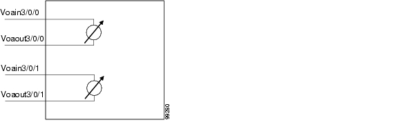
Figure 14-1shows an example of the interfaces for a single WB-VOA module.
Figure 14-1 Single WB-VOA Module Interfaces
Figure 14-2 shows an example of the interfaces for a dual WB-VOA module.
Figure 14-2 Dual WB-VOA Module Interfaces
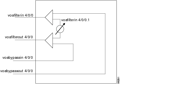
Figure 14-3 shows an example of the interfaces for a single PB-OE module.
Figure 14-3 Single PB-OE Module Interfaces
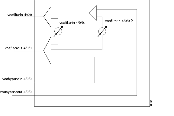
Figure 14-4 shows an example of the interfaces for a dual PB-OE module.
Figure 14-4 Dual PB-OE Module Interfaces
14.2 Initial Troubleshooting Checklist
Follow this initial checklist before proceeding with the troubleshooting procedures:
•
•
•
•
•
•
14.3 Troubleshooting VOA Module Problems
This section contains troubleshooting procedures for VOA module interface problems.
14.3.1 Voain Interface Shows Low Optical Alarm Threshold Error
Symptom The power of the signal monitored by the voain interface on a WB-VOA interface crossed the low optical alarm threshold value and the system raised an alarm.
Table 14-1 describes the potential causes of the symptom and the solutions.
Table 14-1 Voain Interface Shows Low Optical Alarm Threshold Error
The signal is overattenuated.
1.
2.
3.
For more information on setting attenuation values, refer to the Cisco ONS 15530 Optical Transport Turn-Up and Test Guide.
The signal power is too low due to a failure in the signal path.
1.
2.
The attenuation is set too high.
1.
2.
The optical connectors are dirty.
Refer to the Cisco ONS 15530 Cleaning Procedures for Fiber Optic Connections document.
14.3.2 Voafilterin Subinterface Shows Low Optical Alarm Threshold Error
Symptom The power of the signal monitored by the voafilterin subinterface on a PB-OE module crossed the low optical alarm threshold value and the system raised an alarm.
Table 14-2 describes the potential causes of the symptom and the solutions.
14.3.3 Voain Interface Shows High Optical Alarm Threshold Error
Symptom The power of the signal monitored by the voain interface on a WB-VOA module crossed the high optical alarm threshold value and the system raised an alarm.
Table 14-3 describes the potential causes of the symptom and the solutions.
Table 14-3 Voain Interface Shows High Optical Alarm Threshold Error
The signal attenuation is too low.
1.
2.
3.
For more information on setting attenuation values, refer to the Cisco ONS 15530 Optical Transport Turn-Up and Test Guide.
The high alarm threshold value is set too low.
1.
2.
14.3.4 Voafilterin Subinterface Shows High Optical Alarm Threshold Error
Symptom The power of the signal monitored by the voafilterin subinterface on a PB-OE module crossed the high optical alarm threshold value and the system raised an alarm.
Table 14-4 describes the potential causes of the symptom and the solutions.
Table 14-4 Voafilterin Subinterface Shows High Optical Alarm Threshold Error
The signal attenuation is too low.
1.
2.
3.
For more information on setting attenuation values, refer to the Cisco ONS 15530 Optical Transport Turn-Up and Test Guide.
The high alarm threshold value is set too low.
1.
2.
14.3.5 STA LED Continues Blinking After Initialization Complete
Symptom The STA LED continues to blink after initialization of the VOA module should be complete. For removal and reinsertion, initialization completes in a few seconds. For system reload, initialization completes after the entire shelf is initialized.
Table 14-5 describes the potential causes of the symptom and the solutions.
Table 14-5 STA LED Continues Blinking After Initialization Complete
The VOA module is not properly seated.
Remove and reinsert the VOA module as described in the Cisco ONS 15530 Optical Transport Turn-Up and Test Guide.
The carrier motherboard is not properly seated.
1.
2.
3.
14.3.6 Optical Threshold Warnings Not Reported
Symptom The signal power crosses an optical warning threshold and it is not reported.
Table 14-6 describes the potential cause of the symptom and the solution.
![]()
![]()
![]()
![]()
![]()
![]()
![]()
![]()
Posted: Mon Apr 30 12:24:56 PDT 2007
All contents are Copyright © 1992--2007 Cisco Systems, Inc. All rights reserved.
Important Notices and Privacy Statement.