|
|

Table Of Contents
Troubleshooting OADM Module Problems
12.2 Initial Troubleshooting Checklist
12.3 Troubleshooting OADM Module Problems
12.3.1 OADM Module Is Not Recognized
12.3.2 OADM Channel Interfaces Are Not Recognized After a CPU Switch Module Switchover
12.3.3 Waveethernetphy or Wave Interface Is Down
Troubleshooting OADM Module Problems
This chapter describes how to troubleshoot OADM module problems. This chapter includes the following sections:
•
Overview
•
•
12.1 Overview
The OADM (optical add/drop multiplexer) modules are passive devices that optically multiplex and demultiplex a specific band of four ITU wavelengths. The OADM modules supported by the Cisco ONS 15530 each add and drop a band of channels at a node and pass the other bands through. To support the 32-channel spectrum, there are eight different 4-channel OADM modules, each supporting a different band of channels.
In the transmit direction, the OADM modules multiplex signals transmitted by the line cards over optical cross connections and provide the interfaces to connect the multiplexed signal to the DWDM trunk side. In the receive direction, the OADM modules demultiplex the signals from the trunk side before passing them over optical cross connections to the line cards.
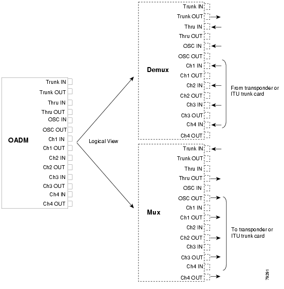
Figure 12-1 shows the physical layout of the OADM module for the channels in band A (1-4) along with a logical view of its multiplexing and demultiplexing functions. Optical signals received from the line card, the Thru IN connector, and the OSC IN connector are multiplexed and sent through the Trunk OUT connector. The optical signal received from the Trunk IN connector is demultiplexed and the OSC signal is sent to the OSC OUT connector; the dropped channels are sent to the line card; and the passed channels are sent to the Thru OUT connector.
Figure 12-1 OADM Module Architecture
12.2 Initial Troubleshooting Checklist
Follow this initial checklist before proceeding with the troubleshooting procedures:
•
•
•
•
•
•
12.3 Troubleshooting OADM Module Problems
This section contains troubleshooting procedures for OADM module problems.
12.3.1 OADM Module Is Not Recognized
Symptom The OADM module does not appear in the show interfaces or the show running-config command output.
Table 12-1 describes the potential causes of the symptom and the solutions.
12.3.2 OADM Channel Interfaces Are Not Recognized After a CPU Switch Module Switchover
Symptom OADM channel interfaces are not recognized after a CPU switch module switchover.
Table 12-2 describes the potential causes of the symptom and the solutions.
12.3.3 Waveethernetphy or Wave Interface Is Down
Symptom The waveethernetphy or the wave interface on the connected transponder is down.
Table 12-3 describes the potential causes of the symptom and the solutions.
![]()
![]()
![]()
![]()
![]()
![]()
![]()
![]()
Posted: Mon Apr 30 14:19:56 PDT 2007
All contents are Copyright © 1992--2007 Cisco Systems, Inc. All rights reserved.
Important Notices and Privacy Statement.