|
|

Table Of Contents
Configuring VOA Module Interfaces
About Variable Optical Attenuation
Configuring VOA Module Interfaces
Configuring Automatic Attenuation
Configuring Manual Attenuation
Displaying the Attenuation Configuration
Configuring Optical Receive Power Thresholds
Displaying the Optical Threshold Configuration
Configuring VOA Module Interfaces
This chapter describes how to configure the VOA modules supported by the Cisco ONS 15530. These modules allow the Cisco ONS 15530 to extend the internodal distances and number of nodes supported for point-to-point, hubbed ring, and meshed ring topology networks.
This chapter includes the following sections:
•
About Variable Optical Attenuation
•
•
•
About Variable Optical Attenuation
The attenuation typically occurs on the input side of the EDFA (erbium-doped fiber amplifier) so that the input power of each band transmitted to the EDFA is equalized. The VOA modules can also attenuate OSC channels, EDFA output (when preamplifying), or individual data channels.
The Cisco ONS 15530 supports two types of VOA modules:
•
•
A PB-OE module selects one or two bands of channels to attenuate and passes on the rest of the signal. By reading pass band after-attenuation power through the photo detector of the PB-OE module, the total power of the sum of the channels in the pass band will be obtained, from which the average power of an individual channel can be deduced if we assume they have been equalized. By monitoring the optical power of the PB-OE module, the total of the channels power of band is deduced by factoring the standard ranges of channels. WB-VOA modules attenuate all the channels it receives. The power reading through the photodetector of the WB-VOA module gives the total power of the signal after attenuation.
Figure 10-1 illustrates the use of PB-OE and WB-VOA modules to perform band based power equalization.
Figure 10-1 Four Band Equalization with Three Power Equalizers
VOA Modules
The VOA modules are half-width modules inserted into a carrier motherboard installed in a Cisco ONS 15530 shelf. The carrier motherboards can be installed in slots 1 through 4 and 7 through 10. All optical connectors are located on the front panel and the connectors are angled and recessed.
Each carrier motherboard can hold up to two VOA modules. There are four types of VOA modules available:
•
•
•
•
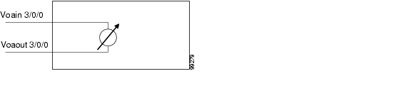
Single WB-VOA Modules
The single WB-VOA modules accept one signal and attenuate all frequencies within that signal. The signal can contain a single channel, such as the OSC, a band of channels, or multiple channel bands.
Single WB-VOA modules have two types of interfaces:
•
•
Figure 10-2 shows the interfaces for the single WB-VOA module.
Figure 10-2 Single WB-VOA Module Interfaces
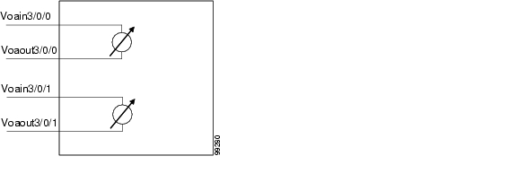
Dual WB-VOA Modules
The dual WB-VOA modules consist of two WB-VOA units that each accepts one signal and attenuates all frequencies within that signal.
Dual WB-VOA modules have two types of interfaces:
•
•
Figure 10-3 shows the interfaces for the dual WB-VOA module.
Figure 10-3 Dual WB-VOA Module Interfaces
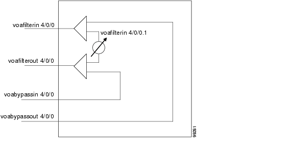
Single Band PB-OE Modules
A single band PB-OE module accepts an incoming signal containing at least two bands, which are split by an optical filter into two components. The first component is attenuated and the second component is passed to another module where it can be attenuated and passed back to the original PB-OE. The PB-OE then recombines the two equalized components into a single signal and sends it out.
Single PB-OE modules have four types of interfaces:
•
•
•
•
Figure 10-4 shows the interfaces for the single PB-OE module.
Figure 10-4 Single PB-OE Module Interfaces
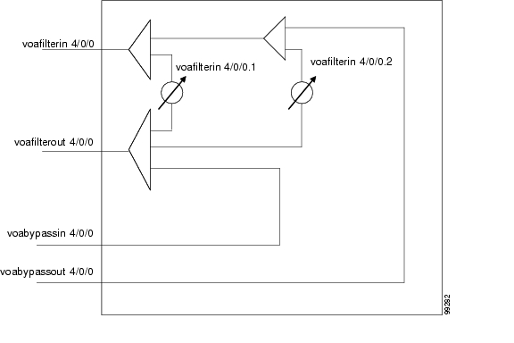
Dual Band PB-OE
If two consecutive bands have to be attenuated, use a dual band PB-OE module. When more than two add bands are to be attenuated, multiple VOA modules can be cascaded. The dual band PB-OE supports bands AB, CD, EF, and GH. Use a dual band PB-OE module to equalize signals with at least two bands.
Dual PB-OE modules have four types of interfaces:
•
•
•
•
Figure 10-5 shows the interfaces for the dual PB-OE module.
Figure 10-5 Dual PB-OE Module Interfaces
Configuring VOA Module Interfaces
To configure optical amplification support on the Cisco ONS 15530, perform the following steps:
Step 1
Step 2
Step 3
For information on configuring topology neighbor information, see the "Configuring Interfaces in the Network Topology" section on page 14-24.
Configuring Attenuation
The Cisco ONS 15530 supports two types of attenuation, automatic and manual. The WB-VOA module allows both automatic and manual attenuation. The PB-OE module only allows manual attenuation.
For more information on configuring attenuation in an amplified network, refer to the
Cisco ONS 15530 Optical Turn-Up and Test Guide publication.Configuring Automatic Attenuation
The WB-VOA modules support automatic attenuation. Once you set a desired signal power, the system checks every second until the signal power comes into attenuable range. Then the system sets the attenuation so that the signal transmits at the desired power value. The system waits 60 seconds before checking the signal power again and adjusting the attenuation if necessary. The system automatically adjusts the attenuation only if it is at least 0.5 dBm out of range.
To configure automatic attenuation on a WB-VOA module interface, perform the following steps:
Note
Example
The following example shows how to configure automatic attenuation on a voain interface on a WB-VOA module:
Switch# configure terminalSwitch(config)# interface voain 1/0/0Switch(config-if)# optical attenuation automatic desired-power 150Configuring Manual Attenuation
The WB-VOA modules and PB-OE modules support manual configuration of attenuation. When you manually configure the attenuation, the interface attenuates at the value specified in the command.
To configure manually attenuation on a VOA module interface, perform the following steps:
Note
Example
The following example shows how to manually configure attenuation on a voafilterin subinterface on a PB-OE module:
Switch# configure terminalSwitch(config)# interface voafilterin 1/0/0.1Switch(config-subif)# optical attenuation manual 20The following example shows how to calculate and configure attenuation on a voain interface on a WB-VOA module:
Switch# show interfaces voain 1/0/0 attenuation desired-power 0Current Output Power: 10.0dBmDesired Output Power: 0.0dBmMinimum settable Attenuation: 3.4dBMaximum settable Attenuation: 30.0dBCurrent set Attenuation: 3.4dB (default)Attenuation needed to achieve Desired Output Power:13.4dBSwitch# configure terminalSwitch(config)# interface voain 1/0/0Switch(config-if)# optical attenuation manual 13.4Displaying the Attenuation Configuration
To display the attenuation configuration, use the following EXEC command:
show interfaces {voafilterin slot/subcard/port.subinterface | voain slot/subcard/port}
Displays the VOA module interface configuration.
Example
The following example shows how to display the attenuation configuration of a voafilterin subinterface:
Switch# show interfaces voafilterin 9/0/0.1voaFilterIn9/0/0.1 is up, line protocol is upHardware is voaFilterIn PortPort Transmit (Tx) Support: FalsePort Receive (Rx) Support: TrueVOA This Port operates on: 2Attenuation Mode: manualMinimum settable Attenuation: 3.7dBMaximum settable Attenuation: 30.0dBCurrent set Attenuation: 3.7dB (default)
Light Quality: Good/In RangeCurrent Output Power: -0.5dBmLow Alarm Threshold Severity: major (default)Low Warning Threshold: -27.0dBm (default)Low Warning Threshold Severity: not alarmed (default)High Warning Threshold: 9.0dBm (default)High Warning Threshold Severity: not alarmed (default)High Alarm Threshold: 11.0dBm (default)High Alarm Threshold Severity: major (default)The following example shows how to display the attenuation configuration of a voain interface:
Switch# show interfaces voain 9/0/0voaIn9/0/0 is up, line protocol is upHardware is voaIn PortPort Transmit (Tx) Support: FalsePort Receive (Rx) Support: TrueVOA This Port operates on: 1Minimum settable Attenuation: 1.7dBMaximum settable Attenuation: 30.0dBLight Quality: Good/In RangeCurrent Output Power: -12.1dBmLow Alarm Threshold Severity: major (default)Low Warning Threshold: -27.0dBm (default)Low Warning Threshold Severity: not alarmed (default)High Warning Threshold: 9.0dBm (default)High Warning Threshold Severity: not alarmed (default)High Alarm Threshold: 11.0dBm (default)High Alarm Threshold Severity: major (default)About Optical Thresholds
You can configure optical thresholds on the VOA module interfaces that issue alarm messages to the system if the optical thresholds are exceeded. Every second the monitoring facility updates the counters that correspond to the alarm thresholds. When the signal degrades, or fails entirely, the system issues alarms to the console. These alarms can help isolate failures in the system and in the network.
Configuring Optical Receive Power Thresholds
The VOA modules have optical receive power thresholds monitored by the Cisco ONS 15530. This section describes four types of alarm threshold configuration procedures:
•
•
•
•
Low power warnings are raised when the received optical power drifts too close to LOL (Loss of Light). Low power alarms show a critical condition of LOL. High power warnings are raised when the received optical power drifts too close to high power alarm conditions. High power alarm are raised when received optical power exceeds the receiver saturation threshold.
To configure power thresholds on VOA module interfaces, perform the following steps, beginning in global configuration mode:
Example
The following example shows how to manually configure an optical threshold on a voafilterin subinterface on a PB-OE module:
Switch# configure terminalSwitch(config)# interface voafilterin 1/0/0.1Switch(config-subif)# optical threshold power receive after-attenuation low alarm -210The following example shows how to configure an optical threshold on a voain interface on a WB-VOA module:
Switch# configure terminalSwitch(config)# interface voain 1/0/0Switch(config-if)# optical threshold power receive after-attenuation high alarm -200Displaying the Optical Threshold Configuration
To display the configuration of an optical threshold for a VOA module interface, use the following EXEC command:
show interfaces {voafilterin slot/subcard/port.subinterface | voain slot/subcard/port}
Displays the VOA module interface configuration.
Example
The following example shows how to display the threshold configuration of a voafilterin subinterface:
Switch# show interfaces voafilterin 2/1/0.2voaFilterIn2/1/0.2 is up, line protocol is upHardware is voaFilterIn PortPort Transmit (Tx) Support: FalsePort Receive (Rx) Support: TrueVOA This Port operates on: 1Attenuation Mode: manualMinimum settable Attenuation: 3.7dBMaximum settable Attenuation: 30.0dBCurrent set Attenuation: 20.0dBLight Quality: Low Warning Threshold ExceededCurrent Output Power: -16.3dBmLow Alarm Threshold: -20.0dBmLow Alarm Threshold Severity: major (Default Value)Low Warning Threshold: -15.0dBmLow Warning Threshold Severity: not-alarm (Default Value)High Warning Threshold: -10.0dBmHigh Warning Threshold Severity: not-alarm (Default Value)High Alarm Threshold: -5.0dBmHigh Alarm Threshold Severity: major (Default Value)The following example shows how to display the threshold configuration of a voain interface:
Switch# show interfaces voain 7/1/0voaIn7/1/0 is up, line protocol is downHardware is voaIn PortPort Transmit (Tx) Support: FalsePort Receive (Rx) Support: TrueVOA This Port operates on: 1Attenuation Mode: manualMinimum settable Attenuation: 1.7dBMaximum settable Attenuation: 30.0dBCurrent set Attenuation: 1.7dBLight Quality: Loss of Light/Low Alarm Threshold ExceededCurrent Output Power: -256.0dBmLow Alarm Threshold: -29.0dBm (Default Value)Low Alarm Threshold Severity: major (Default Value)Low Warning Threshold: -20.0dBmLow Warning Threshold Severity: not-alarm (Default Value)High Warning Threshold: -5.0dBmHigh Warning Threshold Severity: not-alarm (Default Value)High Alarm Threshold: 0.0dBmHigh Alarm Threshold Severity: major (Default Value)
![]()
![]()
![]()
![]()
![]()
![]()
![]()
![]()
Posted: Tue Feb 28 04:25:29 PST 2006
All contents are Copyright © 1992--2006 Cisco Systems, Inc. All rights reserved.
Important Notices and Privacy Statement.