|
|

Table Of Contents
Configuring 4-Port 1-Gbps/2-Gbps FC Aggregation Card Interfaces
About the 4-Port 1-Gbps/2-Gbps FC Aggregation Card
Basic Configuration of the 4-port 1-Gbps/2-Gbps FC Aggregation Card Interfaces
Displaying the 4-port 1-Gbps/2-Gbps FC Aggregation Card Interface Configuration
Configuring Forward Laser Control
Displaying Forward Laser Control Configuration
About Latency and Transmit Buffers
Configuring Transmit Buffer Size for FC, FICON, and ISC
Displaying Transmit Buffer Configuration
Displaying the Cross-Connection Configuration
Displaying the Alarm Threshold Configuration
About Buffer Credit Flow Control
Configuring Buffer Credit Flow Control
Displaying the Buffer Credit Flow Control Configuration
About End-to-End Speed Negotiation
Configuring End-to-End Speed Negotiation
Displaying the End-to-End Speed Negotiation Configuration
Guidelines for Configuring Oversubscription
Displaying Bandwidth Utilization of Oversubscribed Portgroup
Displaying Bandwidth Utilization of Superportgroup
About Performance History Counters
Displaying Performance History Counters
Configuring 4-Port 1-Gbps/2-Gbps FC Aggregation Card Interfaces
This chapter describes how to configure 4-port 1-Gbps/2-Gbps FC (Fibre Channel) aggregation cards on the Cisco ONS 15530. This chapter includes the following sections:
•
About the 4-Port 1-Gbps/2-Gbps FC Aggregation Card
•
•
•
•
•
•
•
•
•
•
•
•
•
About the 4-Port 1-Gbps/2-Gbps FC Aggregation Card
The 4-port 1-Gbps/2-Gbps FC aggregation card uses up to four small form-factor pluggable (SFP) optical transceivers to support client traffic. Each client interface can be configured using the command-line interface (CLI) for FC, fibre connection (FICON), or InterSystem Channel (ISC) links traffic at a 1-Gbps or 2-Gbps rate.
The 4-port 1-Gbps/2-Gbps FC aggregation card connects four 2.5-Gbps electric signals, or portgroup interfaces, to the switch module. The client port data streams must be mapped to one of these portgroup interfaces using the CLI. Only two 1-Gbps client interfaces or one 2-Gbps client interface can be mapped into a single portgroup interface.
The signal on the portgroup interfaces connects through the backplane and the CPU switch module to a 2.5-Gbps ITU trunk card, a 10-Gbps ITU trunk card, a 10-Gbps ITU tunable trunk card, or a 10-Gbps uplink card, where the signal is converted to/from an ITU channel. The cross-connections are configured using the CLI.
The following table summarizes the compatibility of the key features of 4-port 1-Gbps/2-Gbps FC aggregation cards.
Table 5-1 Compatibility of the Features of 4-Port 1-Gbps/2-Gbps Aggregation Cards
Speed Negotiation
Speed Negotiation
Oversubscription
Yes
Oversubscription
Superportgroup
Yes
See footnote1
Superportgroup
OFC2
No
Yes
Yes
OFC
FLC3
See footnote4
Yes
Yes
No
FLC
Flow Control
Yes
Yes
Yes
Yes
Yes
Flow Control
Transmit buffer
Yes
No
No
Yes
Yes
See footnote5
Transmit Buffer
1 Both these features cannot be simultaneously enabled on the same card. However, when a portgroup is connected to a superportgroup, oversubscription is implicitly enabled on that portgroup.
2 OFC = Open Fibre Control.
3 FLC = Forward Laser Control.
4 Implicitly enabled.
5 The transmit buffer is used only during link initialization; thereafter, flow control is used.
The 1-Gbps client traffic from a 4-port 1-Gbps/2-Gbps FC aggregation card is interoperable with the 8-port FC/GE aggregation card at the other end of the network. Any 1-Gbps FC, FICON, or ISC client signal can be transmitted between a 4-port 1-Gbps/2-Gbps FC aggregation card and an 8-port FC/GE aggregation card.
The following table compares the key features of the FC aggregation cards supported on Cisco ONS 15530:
Table 5-2 Comparison of the Features of FC Aggregation Cards Supported on Cisco ONS 15530
Speed Negotiation
No1
No1
Yes
Oversubscription
No
No
Yes
Superportgroup
No
No
Yes
Forward Laser Control
Yes
Yes
Yes
Open Fibre Control
Yes
Yes
Yes
Flow Control
Yes
Yes
Yes
1 End-to-end speed negotiation can be configured on the client devices connected to the aggregation card. However, the card will not participate in speed negotiation and will operate only at the configured speed.
Note
To configure the 4-port 1-Gbps/2-Gbps FC aggregation card on the Cisco ONS 15530, perform the following steps:
Step 1
Step 2
Step 3
Step 4
Step 5
Step 6
Step 7
Step 8
Note
Protocol Monitoring
For FC and FICON traffic, the node monitors the following conditions on the 4-port 1-Gbps/2-Gbps FC aggregation card:
•
•
•
•
•
•
•
•
•
•
•
•
•
For ISC traffic, the node monitors the following conditions on the 4-port 1-Gbps/2-Gbps FC aggregation card:
•
•
•
•
•
•
Support for FC Port Types
The 4-port 1-Gbps/2-Gbps FC aggregation card supports the following FC port types:
•
•
•
•
•
Examples of valid topologies supported by the 4-port 1-Gbps/2-Gbps FC aggregation card include the following:
•
•
•
•
•
The 4-port 1-Gbps/2-Gbps FC aggregation card does not support arbitrated loop topology, including the following port types:
•
•
•
Any combination of these port types is not supported.
The 4-port 1-Gbps/2-Gbps FC aggregation card supports only the standard R_RDY based buffer-to-buffer flow control that is described in the FC-FS and FC-SW-2 specifications. For more information, refer to the "About Buffer Credit Flow Control" section.
Basic Configuration of the 4-port 1-Gbps/2-Gbps FC Aggregation Card Interfaces
The 4-port 1-Gbps/2-Gbps FC aggregation card has three types of interfaces: four twogigabitphy interfaces on the client side, four portgroup interfaces on the trunk side, and one superportgroup interface (virtual) on the trunk side.
To bring up the FC link, perform the following steps (starting in global configuration mode) on the twogigabitphy interfaces:
Step 1
Switch(config)# interface twogigabitphy slot/0/port
Switch(config-if)#
Specifies an interface to configure and enters interface configuration mode.
Step 2
Switch(config-if)# encapsulation {fibrechannel {1g | 2g| auto} [ofc {enable | disable}] | ficon {1g | 2g| auto} [ofc {enable | disable}] | sysplex isc {compatibility | peer {1g | 2g}}}
Configures the interface as either FC, FICON, or ISC. The default is fibrechannel 1g.
Note
Step 3
Switch(config-if)# cdl flow identifier number
Specifies the flow identifier for the signal. The range is 0 to 174.
Step 4
Switch(config-if)# portgroup number
or
Switch(config-if)# superportgroup
Maps the interface to one of four portgroup interfaces.
Maps the interface to the superportgroup interface.
Step 5
Switch(config-if)# no shutdown
Enables the interface.
Step 6
Switch(config-if)# exit
Switch(config)#
Returns to global configuration mode.
Repeat Step 1 through Step 6 for the other twogigabitphy interfaces on the 4-port 1-Gbps/2-Gbps FC aggregation card.
Note
Note
Note
Note
Example
The following example shows how to configure 4-port 1-Gbps/2-Gbps FC aggregation card interfaces:
Switch(config)# interface twogigabitphy 3/0/0Switch(config-if)# encapsulation fibrechannel 1gSwitch(config-if)# cdl flow identifier 30Switch(config-if)# portgroup 0Switch(config-if)# no shutdownSwitch(config-if)# exitDisplaying the 4-port 1-Gbps/2-Gbps FC Aggregation Card Interface Configuration
To display the configuration of 4-port 1-Gbps/2-Gbps FC aggregation card interfaces, use the following EXEC command:
show interfaces {twogigabitphy | portgroup | superportgroup} slot/subcard/port
Displays the interface configuration.
Example
The following example shows how to display the configuration of a twogigabitphy interface configured as a 2-Gbps FC port:
Switch# show interfaces twogigabitphy 3/0/0TwoGigabitPhy3/0/0 is up, line protocol is upOptical Transceiver:Single ModeSignal quality:GoodEncapsulation:Fibre channel Rate:1G Ofc:offflow control:disabledTime of last "encapsulation" change 08:03:20Portgroup mapping:2Forward laser control:OffFlow-identifier:90Loopback not setProtection Mode:None Interface state:ActiveThreshold monitored for:NoneReceived Frames:0Received Bytes:0Transmit Frames:0Transmit Bytes:0Code violation and running disparity error count( 8b10b cvrd):0RX CRC errors:0TX CRC errors:0Link Failures:0Loss of Sync:0Loss of Light:0Sequence Protocol Error count:0Invalid Transmission Word count:885 minute input rate 0 bits/sec, 0 frames/sec5 minute output rate 0 bits/sec, 0 frames/secTransmit Buffer size is 256 bytesLast clearing of "show interface" counters 08:03:40Hardware is 2gfc_phy_portThe following example shows how to display the configuration of a portgroup interface:
Switch# show interfaces portgroup 9/0/0Portgroup9/0/0 is up, line protocol is upReceived Frames: 127294406966Transmit Frames: 127183980670Oversized Frames: 0Undersized Frames: 0CRC error count: 0Code violation and running disparity error count(cvrd): 0Number of times SF threshold exceeded: 0Secondary fabric CVRD count: 0CDL HEC error count: 0SII Mismatch error count: 0Oversubscription: DisabledHardware is 2gfc_portgroupThe following example shows how to display the configuration of a superportgroup interface:
Switch# show interfaces superPortgroup 9/0/0SuperPortgroup9/0/0 is up, line protocol is up--------------------PortGrp Intf FlowID------------ ------Portg9/0/0 100Portg9/0/1 101-----------------------------------------------------------------------Client Intf Max Subrate Cfgd Input Rate B/WRate Rx (MB/s) (MB/s) Share------------ ---- ------------ ---------- -----TwoGi9/0/0 212 150 90 yesTwoGi9/0/1 106 106 60 yesTwoGi9/0/2 212 200 15 yes---------------------------------------------------Total Bandwidth: 500 MB/s Free Bandwidth: 44 MB/sConfigured Bandwidth: 456 MB/sHardware is 2gfc_superportgroupAbout Forward Laser Control
When loss of light occurs on a receive interface (client, trunk, or intermediate) in a DWDM network, the corresponding transmitting laser on the far end of the network continues to function and may send unreliable information to the client. Forward Laser Control (FLC) provides a means to quickly shut down a transmitting laser when a receive signal failure occurs and pass the fault to the client devices. Loss of light can result from a failure in upstream optics or in the client equipment, a laser shutdown on an upstream node in the network, or a receiver failure in the module. For more information on FLC, see the "About Forward Laser Control" section on page 8-13.
Configuring Forward Laser Control
To configure FLC on the twogigabitphy interfaces, perform the following steps, starting in global configuration mode:
Displaying Forward Laser Control Configuration
To display the forward laser control configuration, use the following EXEC command:
Example
The following example shows how to display the FLC configuration:
Switch# show interfaces twogigabitphy 9/0/0TwoGigabitPhy9/0/0 is up, line protocol is upOptical Transceiver: Single ModeSignal quality: GoodEncapsulation: Fibre channel Rate: 2G Ofc: offflow control: disabledTime of last "encapsulation" change 1d02hPortgroup mapping: 0>> Forward laser control: On
Flow-identifier: 90Loopback not setProtection Mode: None Interface state: ActiveThreshold monitored for: NoneReceived Frames: 0Received Bytes: 0Transmit Frames: 0Transmit Bytes: 0Code violation and running disparity error count( 8b10b cvrd): 0RX CRC errors: 0TX CRC errors: 0Link Failures: 0Loss of Sync: 1Loss of Light: 1Sequence Protocol Error count: 0Invalid Transmission Word count: 05 minute input rate 0 bits/sec, 0 frames/sec5 minute output rate 0 bits/sec, 0 frames/secTransmit Buffer size is 512 bytesLast clearing of "show interface" counters 1d02hHardware is 2gfc_phy_portAbout Latency and Transmit Buffers
The 4-port 1-Gbps/2-Gbps FC aggregation card adds latency to the transmission of FC, FICON, and ISC traffic depending on the services configured. Table 5-3 and Table 5-4 show the latency value for the various configurations on the transmitting node.
Note
The transmit buffer on the receiving node compensates for the packet jitter effects due to service multiplexing on the trunk. You must correctly configure the size of this transmit buffer to ensure that no buffer underflow or overflow occurs. Symptoms of an improperly configured transmit buffer on the FC or FICON port include CRC errors, frame drops, and transmission word errors detected by the receiving FC or FICON client node.
Configuring Transmit Buffer Size for FC, FICON, and ISC
To configure the transmit buffer on the receiving node, perform the following steps, starting in global configuration mode:
Note
Table 5-5 and Table 5-6 provide transmit buffer settings for various configurations possible on the remote node.
Example
The following example shows how to configure the transmit buffer size on the receiving node:
Switch(config)# interface twogigabitphy 3/0/0Switch(config-if)# shutdownSwitch(config-if)# tx-buffer size 1280Switch(config-if)# no shutdownDisplaying Transmit Buffer Configuration
To display the transmit buffer configuration, use the following EXEC command:
Example
The following example shows how to display the transmit buffer configuration:
Switch# show interfaces twogigabitphy 3/0/0TwoGigabitPhy3/0/0 is up, line protocol is upOptical Transceiver:Single ModeSignal quality:GoodEncapsulation:Fibre channel Rate:1G Ofc:offflow control:disabledTime of last "encapsulation" change 08:03:20Portgroup mapping:2Forward laser control:OffFlow-identifier:90Loopback not setProtection Mode:None Interface state:ActiveThreshold monitored for:NoneReceived Frames:0Received Bytes:0Transmit Frames:0Transmit Bytes:0Code violation and running disparity error count( 8b10b cvrd):0RX CRC errors:0TX CRC errors:0Link Failures:0Loss of Sync:0Loss of Light:0Sequence Protocol Error count:0Invalid Transmission Word count:885 minute input rate 0 bits/sec, 0 frames/sec5 minute output rate 0 bits/sec, 0 frames/secLast clearing of "show interface" counters 08:03:40Hardware is 2gfc_phy_portAbout Cross-Connections
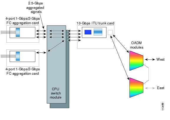
The client signal follows a path of interface cross connections through the Cisco ONS 15530. Figure 5-1 shows an example of cross-connections. Knowing the path of a signal through the shelf helps with system management and troubleshooting.
Figure 5-1 Cross-Connection Example for 4-Port 1-Gbps/2-Gbps FC Aggregation Card Interfaces
Configuring Cross-Connections
The aggregated signals from 4-port 1-Gbps/2-Gbps FC aggregation cards pass through the switch module to the 2.5-Gbps ITU trunk card, 10-Gbps ITU trunk card, 10-Gbps ITU tunable trunk card, or the 10-Gbps uplink card. To establish a cross-connection through the switch module, perform the following steps, beginning in global configuration mode:
Switch(config)# connect interface1 interface2
Creates a cross-connection between two interfaces through the switch module.
Note
Examples
The following example shows how to configure a cross-connection between a 4-port 1-Gbps/2-Gbps FC aggregation card and a 2.5-Gbps ITU trunk card:
Switch(config)# connect portgroup 3/0/0 waveethernetphy 3/0The following example shows how to configure a cross-connection between a 4-port 1-Gbps/2-Gbps FC aggregation card and a 10-Gbps ITU trunk card:
Switch(config)# connect portgroup 3/0/0 waveethernetphy 3/0.1The following example shows how to configure a cross-connection between a 4-port 1-Gbps/2-Gbps FC aggregation card and a 10-Gbps uplink card:
Switch(config)# connect portgroup 3/0/0 tengigethernetphy 3/0.1Displaying the Cross-Connection Configuration
To display the cross-connection configuration, use the following privileged EXEC command:
show connect [edge | intermediate [sort-channel | interface interface]]
Displays the signal cross-connection configuration through the system.
Examples
The following example shows the cross-connections:
Switch# show connectIndex Client Intf Trunk Intf Kind C2TStatus T2CliStatus----- --------------- --------------- ----------- ---------- ---------6 Portg3/0/1 WaveE9/0.1 Provisioned Up UpThe following example shows the intermediate cross-connections:
Switch# show connect intermediateclient/ wave wave wdmwave client patch filter trk channel------------ ------------ ------- ------ ----- -------Gigab4/0/3 WaveE2/0 2/0/0* 0/0/0 0/0 252/0/1 0/1/0 0/1 25TwoGi9/0/0 WaveE2/0 2/0/0* 0/0/0 0/0 252/0/1 0/1/0 0/1 25TwoGi9/0/1 WaveE2/0 2/0/0* 0/0/0 0/0 252/0/1 0/1/0 0/1 25TwoGi9/0/2 WaveE2/0 2/0/0* 0/0/0 0/0 252/0/1 0/1/0 0/1 25TwoGi9/0/3 WaveE2/0 2/0/0* 0/0/0 0/0 252/0/1 0/1/0 0/1 25About Alarm Thresholds
You can configure thresholds on the 4-port 1-Gbps/2-Gbps FC aggregation card interfaces that issue alarm messages to the system if the thresholds are exceeded.
Every second, the monitoring facility updates the counters that correspond to the alarm thresholds. When the signal degrades, or fails entirely, the node issues alarms to the console. These alarms can help isolate failures in the node and in the network. Signal degrade and signal failure are indicators of signal quality based on the signal data stream. Signal degrade is reported when the number of errors reported per second is more than the signal degrade threshold. Signal failure is reported when the number of errors per second is more than the signal failure threshold.
You can configure more than one threshold list on an interface. The threshold lists cannot have overlapping counters; only one counter can be set for the interface. Also, the threshold list name cannot begin with the text string "default" because that string is reserved for use by the node.
Configuring Alarm Thresholds
To configure alarm thresholds on the 4-port 1-Gbps/2-Gbps FC aggregation card interfaces, perform the following steps, beginning in global configuration mode:
Step 1
Switch(config)# threshold-list name
Switch(config-t-list)#
Creates or selects the threshold list to configure and enters threshold list configuration mode.
Note
Step 2
Switch(config-t-list)# notification-throttle timer seconds
Configures the SNMP notification timer. The default value is 5 seconds. (Optional)
Step 3
Switch(config-t-list)# threshold name {cvrd | cdl hec | crc | sonet-sdh section cv | tx-crc} {failure | degrade} [index value]
Switch(config-threshold)#
Specifies a threshold type to modify and enters threshold configuration mode.
Step 4
Switch(config-threshold)# value rate value
Specifies the threshold rate value. This value is the negative power of 10 (10-n).
Step 5
Switch(config-threshold)# description text
Specifies a description of the threshold. The default value is the null string. (Optional)
Step 6
Switch(config-threshold)# exit
Switch(config-t-list)#
Returns to threshold list configuration mode.
Repeat Step 3 through Step 6 to configure more thresholds in the threshold list.
Step 7
Switch(config-t-list)# exit
Switch(config)#
Returns to global configuration mode.
Step 8
Switch(config)# interface interface
Switch(config-if)#
Selects the interface to configure and enters interface configuration mode.
Step 9
Switch(config-if)# threshold-group name
Configures the threshold list on the interface.
Table 5-7 lists the threshold error rates in errors per second for Fiber Channel 1G and 2G signals.
Example
The following example shows how to create an alarm threshold list and configure that list for 4-port 1-Gbps/2-Gbps FC aggregation card interfaces:
Switch# configure terminalSwitch(config)# threshold-list twogigabitphy-countersSwitch(config-t-list)# threshold name tx-crc degradeSwitch(config-threshold)# value rate 9Switch(config-threshold)# exitSwitch(config-t-list)# threshold name tx-crc failureSwitch(config-threshold)# value rate 7Switch(config-threshold)# exitSwitch(config-t-list)# exitSwitch(config)# interface twogigabitphy 3/0/0Switch(config-if)# threshold-group twogigabitphy-countersDisplaying the Alarm Threshold Configuration
To display the configuration of a threshold list and the threshold group for a twogigabitphy interface, use the following EXEC commands:
show threshold-list [name]
Displays the threshold group configuration.
show interfaces twogigabitphy slot/subcard/slot
Displays the interface configuration.
Examples
The following example shows how to display the configuration of a threshold group:
Switch# show threshold-list twogigabitphy-countersThreshold List Name: twogigabitphy-countersNotification throttle timer : 5 (in secs)Threshold name : CRC Severity : DegradeValue : 10e-9APS Trigger : Not setThreshold name : CRC Severity : FailureValue : 10e-7APS Trigger : Not setThe following example shows how to display the threshold group information for an interface:
Switch# show interfaces twogigabitphy 3/0/0TwoGigabitPhy3/0/0 is up, line protocol is upOptical Transceiver:Single ModeSignal quality:GoodEncapsulation:Fibre channel Rate:1G Ofc:offflow control:disabledTime of last "encapsulation" change 08:14:03Portgroup mapping:2Forward laser control:OffFlow-identifier:90Loopback not setProtection Mode:None Interface state:ActiveThreshold monitored for:tx-crcSF set value:10e-7 (100 in 1 secs)SD set value:10e-9 (10 in 10 secs)Received Frames:0Received Bytes:0Transmit Frames:0Transmit Bytes:0Code violation and running disparity error count( 8b10b cvrd):0RX CRC errors:0TX CRC errors:0Link Failures:0Loss of Sync:0Loss of Light:0Sequence Protocol Error count:0Invalid Transmission Word count:885 minute input rate 0 bits/sec, 0 frames/sec5 minute output rate 0 bits/sec, 0 frames/secTransmit Buffer size is 256 bytesLast clearing of "show interface" counters 08:14:23Hardware is 2gfc_phy_portAbout Buffer Credit Flow Control
Buffer credit flow control increases the throughput of FC links over the DWDM network. Flow control requires that FC devices receive acknowledgement for transmitted frames before more frames can be transmitted. Although a certain number of outstanding transmitted frames is allowed (buffer credits), throughput can drop considerably as the distance grows. By configuring flow control on the twogigabitphy interfaces of the 4-port 1-Gbps/2-Gbps FC aggregation card, FC throughput can be maintained across much larger distances.
The 4-port 1-Gbps/2-Gbps FC aggregation card supports only the standard R_RDY based buffer-to-buffer flow control that is described in the FC-FS and FC-SW-2 specifications. Vendor specific flow control mechanisms are not supported. If client devices use vendor specific flow control, flow control on the 4-port 1-Gbps/2-Gbps FC aggregation card will become inactive. The traffic will, however, continue to flow without any errors. In such a case, you will not be able to utilize the 4-port 1-Gbps/2-Gbps FC aggregation card's FC distance extension capabilities. If flow control is disabled at the 4-port 1-Gbps/2-Gbps FC aggregation card, you can connect clients that use either standard or vendor specific flow control.
The 4-port 1-Gbps/2-Gbps FC aggregation card supports both symmetric and asymmetric modes of buffer credit flow control. In the symmetric mode, the FC client devices at both ends transmit frame bursts of sizes up to the lower value of the buffer credit capabilities advertised by them at FC login. In the asymmetric mode, the FC client at each end transmits frame bursts up to the full size of the peer FC client's credit buffers. Most FC devices operate in symmetric mode.
Asymmetric flow control mode is the default in 4-port 1-Gbps/2-Gbps FC aggregation cards with Functional version 1.20 or later and Cisco IOS version 12.2(29)SV or later. The 4-port 1-Gbps/2-Gbps FC aggregation card operates in the symmetric flow control mode only if any of the following conditions are met:
•
•
•
Symmetric flow control is the default in 4-port 1-Gbps/2-Gbps FC aggregation cards with Functional versions prior to 1.20 and Cisco IOS versions prior to 12.2(29)SV. However, the asymmetric mode is selected if you enable asymmetric flow control at the local end while the remote node is operating in asymmetric mode. If the client at either end is operating in symmetric mode, flow control will operate in symmetric mode irrespective of the specified configuration.
If oversubscription is enabled, you must ensure that the buffer-to-buffer credit value configured on the client devices does not exceed the oversubscription memory credit size (211 for 1 Gbps and 939 for 2 Gbps).
Configuring Buffer Credit Flow Control
To configure buffer credit flow control on 4-port 1-Gbps/2-Gbps FC aggregation card twogigabitphy interfaces, perform the following steps, beginning in global configuration mode:
Asymmetric flow control must be used only if the following conditions are met:
–
–
–
Example
The following example shows how to configure buffer credit flow control on a 4-port 1-Gbps/2-Gbps FC aggregation card twogigabitphy interface:
Switch# configure terminalSwitch(config)# interface twogigabitphy 3/0/0Switch(config-if)# encapsulation fibrechannel 1gSwitch(config-if)# cdl flow identifier 30Switch(config-if)# portgroup 0Switch(config)# tx-buffer size 256Switch(config-if)# flow controlSwitch(config-if)# no shutdownSwitch(config-if)# exitDisplaying the Buffer Credit Flow Control Configuration
To display the buffer credit flow control configuration on 4-port 1-Gbps/2-Gbps FC aggregation card twogigabitphy interfaces, use the following EXEC command:
show interfaces twogigabitphy slot/subcard/port
Displays the interface configuration.
Examples
The following example shows how to display the configuration of a twogigabitphy interface configured with flow control:
Switch# show interfaces twogigabitphy 9/0/3TwoGigabitPhy9/0/3 is up, line protocol is upOptical Transceiver: Single ModeSignal quality: GoodEncapsulation: Fibre channel Rate: 1G Ofc: offTime of last "encapsulation" change 1d02hPortgroup mapping: 3Forward laser control: OffFlow-identifier: 93Loopback not setProtection Mode: None Interface state: ActiveThreshold monitored for: NoneReceived Frames: 155803Received Bytes: 334600660Transmit Frames: 158006Transmit Bytes: 339331172Code violation and running disparity error count( 8b10b cvrd): 0RX CRC errors: 0TX CRC errors: 0Link Failures: 0Loss of Sync: 0Loss of Light: 0Sequence Protocol Error count: 0Invalid Transmission Word count: 05 minute input rate 0 bits/sec, 0 frames/sec5 minute output rate 0 bits/sec, 0 frames/secTransmit Buffer size is 256 bytesLast clearing of "show interface" counters 00:00:17Hardware is 2gfc_phy_portAbout End-to-End Speed Negotiation
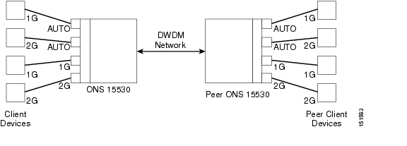
The 4-port 1-Gbps/2-Gbps FC aggregation card supports end-to-end speed negotiation. This allows client devices connected through the 4 port 1-Gbps/2-Gbps FC aggregation card to negotiate a common maximum transmission speed automatically.
When speed negotiation is enabled, the link will negotiate to a mutually supported maximum transmission speed on all interfaces (the twogigabitphy interface, the client interface connected directly to it, the peer twogigabitphy interface, and the peer client interface) in the link. For instance, if both the client interfaces are configured at 2 Gbps, the negotiated link speed will also be 2 Gbps. However, if one or both of these interfaces is configured at 1 Gbps, the link speed will be 1 Gbps. If any of the interfaces is configured at a fixed speed, all interfaces in the link will communicate at that speed. If different interfaces are configured at different fixed speeds, the link will not be able to negotiate a common speed.
Figure 5-2 End-to-End Speed Negotiation
To enable speed negotiation on a twogigabitphy interface, configure encapsulation on the interface and set the speed to auto.
Note
To enable end-to-end speed negotiation, the following requirements must be met:
•
•
•
Configuring End-to-End Speed Negotiation
To configure end-to-end speed negotiation, perform the following steps, starting in global configuration mode:
Example
The following example shows how to configure end-to-end speed negotiation on a 4-port 1-Gbps/2-Gbps FC aggregation card twogigabitphy interface:
Switch# configure terminalSwitch(config)# interface twogigabitphy 7/0/0Switch(config-if)# encapsulation fibrechannel autoSwitch(config-if)# exit
Note
Note
Displaying the End-to-End Speed Negotiation Configuration
To display the end-to-end speed negotiation configuration on 4-port 1-Gbps/2-Gbps FC aggregation card twogigabitphy interfaces, use the following EXEC command:
show interfaces twogigabitphy slot/subcard/port
Displays the interface configuration.
The following table describes the values of the Rate field in the output of the show interfaces command:
NEG
Speed negotiation is in progress.
N1G
Speed has been negotiated to 1 Gbps.
N2G
Speed has been negotiated to 2 Gbps.
Example
The following example shows how to display the configuration of a twogigabitphy interface configured with end-to-end speed negotiation:
Switch# show interfaces twogigabitphy 9/0/3TwoGigabitPhy9/0/3 is up, line protocol is upOptical Transceiver: Single ModeSignal quality: Goodflow control(symmetric): enabled, and activeTime of last "encapsulation" change 00:00:52Portgroup mapping: 3Local Login Credits: 16 Remote Login Credits: 16Forward laser control: OnFlow-identifier: 93Loopback not setProtection Mode: None Interface state: ActiveThreshold monitored for: NoneReceived Frames: 1796271Received Bytes: 2127476584Transmit Frames: 1799846Transmit Bytes: 2030633756Code violation and running disparity error count( 8b10b cvrd): 0RX CRC errors: 0TX CRC errors: 0Link Failures: 0Loss of Sync: 0Loss of Light: 0Sequence Protocol Error count: 0Invalid Transmission Word count: 05 minute input rate 47222000 bits/sec, 5241 frames/sec5 minute output rate 44776000 bits/sec, 4965 frames/secTransmit Buffer size is 2580 bytesLast clearing of "show interface" counters 00:00:32Hardware is 2gfc_phy_portAbout Oversubscription
You can oversubscribe the 4-port 1-Gbps/2-Gbps FC aggregation card to efficiently utilize unused portgroup bandwidth. Oversubscription is supported only in the FC/FICON mode and not in the ISC mode.
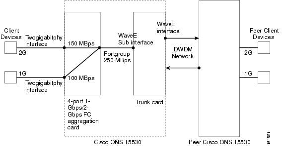
Typically, to transfer 2-Gbps FC data at full rate over a 2.5-Gbps portgroup, only 84% of the portgroup bandwidth is utilized. Similarly, to transfer 1-Gbps FC data at full rate over a 2.5 Gbps portgroup, only 42% of the portgroup bandwidth is utilized. By oversubscribing the 4-port 1-Gbps/2-Gbps FC aggregation card, you can utilize the unused bandwidth to transfer FC data. Figure 5-3 shows an example of an oversubscribed portgroup.
Figure 5-3 Oversubscribed Portgroup Example
In most storage applications, the bandwidth used is much less than the configured 1 Gbps or 2 Gbps rate. This unused bandwidth can be used to transfer useful data. If you know the type of the application and its bandwidth utilization, you can minimize bandwidth wastage by allocating only the required bandwidth for each client. The remaining bandwidth can be allocated to other FC clients; thus, each 2.5-Gbps portgroup can be used to its fullest capacity by multiple clients.
To oversubscribe a 4-port 1-Gbps/2-Gbps FC aggregation card, you must configure subrates for every client interface. Subrate is specified in megabytes per second (MBps). For example, to permit full-rate 1-Gbps or 2-Gbps FC traffic over an oversubscribed portgroup, you must specify 106 MBps or 212 MBps as the subrate for that client interface. By default, for each client interface, subrate is set to 1 MBps.
Subrates can be configured only for those client interfaces that are already connected to an oversubscribed portgroup or superportgroup. A superportgroup is a set of oversubscribed portgroups. For more information on superportgroups, see "About Superportgroup" section.
By default, unused bandwidth in the portgroup will be used by other clients based on demand. For example, if two 2-Gbps FC ports are each configured at a 125 MBps subrate, and one of them is utilizing only 75 MBps of the available bandwidth, the other port can use 1 to 175 MBps of the portgroup bandwidth. If you do not want to permit the sharing of bandwidth, you can lock the bandwidth of a client interface. When the client bandwidth is locked, it will not share its configured bandwidth with other clients. However, if available, it will borrow bandwidth from other unlocked clients in the same portgroup or superportgroup.
Guidelines for Configuring Oversubscription
•
•
•
•
•
–
–
–
–
Configuring Oversubscription
To configure oversubscription, first perform the steps described in the "Basic Configuration of the 4-port 1-Gbps/2-Gbps FC Aggregation Card Interfaces" section, and then continue with the following steps (beginning in global configuration mode):
To move a twogigabitphy client interface from an oversubscribed portgroup to a non-oversubscribed portgroup, perform the following steps:
Step 1
Step 2
Step 3
Step 4
To enable or disable oversubscription on a portgroup, perform the following steps:
Step 1
Step 2
Step 3
Examples
The following example shows how to enable oversubscription on a 4-port 1-Gbps/2-Gbps FC aggregation card:
Switch# configure terminalSwitch(config)# interface portgroup 7/0/0Switch(config-if)# over-subscriptionSwitch(config-if)# exitThe following example shows how to configure the subrate:
Switch(config)# interface twogigabitphy 7/0/0Switch(config-if)# sub-rate 50Switch(config-if)# exitThe following example shows how to disable bandwidth sharing:
Switch(config)# interface twogigabitphy 7/0/0Switch(config-if)# sub-rate 50 lockSwitch(config-if)# exit
Displaying Bandwidth Utilization of Oversubscribed Portgroup
To display the bandwidth utilization of the oversubscribed portgroup, use the following EXEC command:
Example
The following example shows how to display the oversubscription configuration and the portgroup bandwidth utilization:
Switch# show interfaces portgroup 9/0/3Portgroup9/0/3 is up, line protocol is upReceived Frames: 457659558Transmit Frames: 471666783Oversized Frames: 0Undersized Frames: 0CRC error count: 0Code violation and running disparity error count(cvrd): 0Number of times SF threshold exceeded: 0Secondary fabric CVRD count: 0CDL HEC error count: 0SII Mismatch error count: 0-----------------------------------------------------------Client Intf Max Subrate Cfgd Input Rate B/W FlowIDRate Rx (MB/s) (MB/s) Share------------ ---- ------------ ---------- ----- ------TwoGi9/0/3 212 150 66 yes 93TwoGi9/0/1 106 100 30 yes 91-----------------------------------------------------------Total Bandwidth: 250 MB/s Free Bandwidth: 0 MB/sConfigured Bandwidth: 250 MB/sHardware is 2gfc_portgroupAbout Superportgroup
The 4-port 1-Gbps/2-Gbps FC aggregation card supports up to four 2.5-Gbps portgroups. You can group two or more of these portgroups to create a superportgroup. A superportgroup enables you to aggregate the unused bandwidth of all the portgroups to form a pool of unused bandwidth, which can be shared by the clients. For example, if you create a superportgroup with four client interfaces, each with a subrate of 187 MBps, then three portgroups (each 250 MBps) will be sufficient. The fourth 2.5 Gbps lane of the trunk card can be used to transport any other type of data such as GigE or ESCON. Figure 5-4 shows an example of a superportgroup.
Figure 5-4 Superportgroup Example
When a portgroup is associated to the superportgroup, oversubscription is automatically enabled on that portgroup. If you disassociate a portgroup from the superportgroup, oversubscription is automatically disabled on that portgroup. Moreover, while superportgroup is configured, oversubscription cannot be enabled on any other portgroup (in the same 4-port 1-Gbps/2-Gbps FC aggregation card) that is not part of the superportgroup. A portgroup that is associated to a superportgroup cannot be connected to any twogigabitphy interfaces.
The portgroups that are part of the superportgroup must be cross-connected to the same trunk card only. The trunk flow identifier will be configured on the look-up table of the ITU2 trunk card. If that flow ID causes a conflict with the other flow IDs programmed in the ITU2 trunk card, the superportgroup cross-connections or the portgroup associations with the superportgroup will be rejected.
Note
To configure superportgroup, the following system requirements must be met:
•
•
•
•
Configuring Superportgroup
To configure superportgroup on the 4-port 1-Gbps/2-Gbps FC aggregation card, perform the following steps, beginning in global configuration mode:
To associate a twogigabitphy interface connected to the superportgroup to any other portgroup, perform the following steps in the given sequence:
Step 1
Step 2
Step 3
Step 4
Example
The following example shows how to configure superportgroup on a 4-port 1-Gbps/2-Gbps FC aggregation card:
Switch# configure terminalSwitch(config)# interface superportgroup 4/0/0Switch(config-if)# portgroup 0 identifier 16Switch(config-if)# portgroup 1 identifier 17Switch(config-if)# portgroup 2 identifier 18Switch(config-if)# exitSwitch(config)# interface twogigabitphy 4/0/0Switch(config-if)# superportgroupSwitch(config-if)# sub-rate 212 lockSwitch(config-if)# exitSwitch(config)# interface twogigabitphy 4/0/1Switch(config-if)# superportgroupSwitch(config-if)# sub-rate 212Switch(config-if)# exitSwitch(config)# interface twogigabitphy 4/0/2Switch(config-if)# superportgroupSwitch(config-if)# sub-rate 212Switch(config-if)# exitSwitch(config)# interface twogigabitphy 4/0/3Switch(config-if)# superportgroupSwitch(config-if)# sub-rate 114Switch(config-if)# exitDisplaying Bandwidth Utilization of Superportgroup
To display the superportgroup configuration and to check the utilization of the portgroup bandwidth, use the following EXEC commands:
Example
The following example shows how to display the superportgroup configuration and the portgroup bandwidth utilization:
Switch# show interfaces superportgroup 7/0/0SuperPortgroup4/0/0 is up, line protocol is up--------------------PortGrp Intf FlowID------------ ------Portg4/0/0 16Portg4/0/1 17Portg4/0/2 18-----------------------------------------------------------------------Client Intf Max Subrate Cfgd Input Rate B/WRate Rx (MB/s) (MB/s) Share------------ ---- ------------ ---------- -----TwoGi4/0/0 212 212 181 noTwoGi4/0/1 212 212 120 yesTwoGi4/0/2 212 212 120 yesTwoGi4/0/3 212 114 84 yes---------------------------------------------------Total Bandwidth: 750 MB/s Free Bandwidth: 0 MB/sConfigured Bandwidth: 750 MB/sHardware is 2gfc_superportgroupSwitch# show interfaces TwoGigabitPhy 4/0/0TwoGigabitPhy4/0/0 is up, line protocol is upOptical Transceiver: Single ModeSignal quality: GoodEncapsulation: Fibre channel Rate: N2G Ofc: offConfigured Subrate: 212 MB/s Bandwidth Sharing: noflow control(symmetric): enabled, and activeTime of last "encapsulation" change 00:04:13Local Login Credits: 16 Remote Login Credits: 16Forward laser control: OnLoopback not setProtection Mode: None Interface state: ActiveConfigured threshold Group(s): bp2Threshold monitored for: 8b10b cvrdSF set value: 10e-5 (22149 in 1 secs)SD set value: 10e-7 (221 in 1 secs)Threshold monitored for: tx-crcSF set value: 10e-5 (18846 in 1 secs)SD set value: 10e-7 (200 in 1 secs)Received Frames: 6696038Received Bytes: 7544908504Transmit Frames: 6696052Transmit Bytes: 7542196596Code violation and running disparity error count( 8b10b cvrd): 0RX CRC errors: 0TX CRC errors: 0Link Failures: 0Loss of Sync: 0Loss of Light: 0Sequence Protocol Error count: 0Invalid Transmission Word count: 05 minute input rate 211931000 bits/sec, 23515 frames/sec5 minute output rate 211854000 bits/sec, 23515 frames/secTransmit Buffer size is 512 bytesLast clearing of "show interface" counters 00:00:59Hardware is 2gfc_phy_portSwitch# show interfaces Portgroup 4/0/0Portgroup4/0/0 is up, line protocol is upReceived Frames: 741369086Transmit Frames: 741246018Oversized Frames: 0Undersized Frames: 0CRC error count: 0Code violation and running disparity error count(cvrd): 0Number of times SF threshold exceeded: 0Secondary fabric CVRD count: 0CDL HEC error count: 0SII Mismatch error count: 0Oversubscription: Enabled, Trunk Flow-identifier: 16-----------------------------------------------------------Client Intf Max Subrate Cfgd Input Rate B/W FlowIDRate Rx (MB/s) (MB/s) Share------------ ---- ------------ ---------- ----- -----------------------------------------------------------------Total Bandwidth: 250 MB/s Free Bandwidth: 250 MB/sConfigured Bandwidth: 0 MB/sHardware is 2gfc_portgroupAbout Performance History Counters
Cisco ONS 15530 supports 15 minute based performance history counters. You can use the performance history counters to track the performance of the Cisco ONS 15530 interfaces.
There are three types of performance history counters: current, 15-minute history, and 24-hour. Cisco ONS 15530 uses these counters to store the performance data for the following time periods:
•
•
•
When the Cisco ONS 15530 system boots up, a continuously incrementing current counter is started. At the end of 15 minutes, this current counter is converted to a static 15-minute history counter with an interval number 1, and a new current counter is started with an interval number 2.
This process continues for 24 hours, by the end of which, ninety six 15-minute history counters are created. After the creation of the ninety sixth 15-minute history counter, a new 24-hour counter is created along with a current counter that has an interval number 1. The 24-hour counter has the aggregated data of all the ninety six 15-minute history counters.
The 15-minute history counters that are created thereafter overwrite the existing set of ninety six 15-minute history counters, in the order they were created. Again, after the creation of the ninety sixth 15-minute history counter, the contents of the existing 24-hour counter are overwritten with new values. This entire process continues in a cyclic fashion.
Note
The performance history counters synchronize periodically from the primary CPU switch module to the standby CPU switch module enabling the system to preserve the performance data across a CPU switch module switchover.
Note
Displaying Performance History Counters
To display the performance history counters, use the following EXEC commands:
show performance current [interface]
Displays the current counter for the specified interface1 .
show performance history [interface] [interval number]
Displays the 15-minute history counter for the specified interface and interval number1.
show performance 24-hour [interface]
Displays the 24-hour counter for the specified interface1.
1 If you do not specify the interface or interval number, the performance history counters for all interfaces or interval numbers are displayed.
To clear and reset all performance history counters, use the following EXEC command:
clear performance history [interface]
Clears the performance history counters for the specified interface.
Examples
The following example shows how to display the current counter for a twogigabitphy interface:
Switch# show performance current twogigabitPhy 4/0/3Current 15 minute performance register--------------------------------------Interface : TwoGigabitPhy4/0/3Interval Number : 24Elapsed Time(seconds) : 688Valid Time(seconds) : 688Received Frames : 326186915Received Bytes : 41751926848Transmit Frames : 326173811Transmit Bytes : 41750247868RX CRC : 0Code violation and running disparity error count : 0Link Failures : 0Loss of Sync : 0Loss of Light : 0Sequence Protocol Error count : 0Invalid Transmission Word count : 0The following example shows how to display the 15-minute history counter for a twogigabitphy interface:
Switch# show performance history twoGigabitPhy 4/0/3 7515 minute performance history register--------------------------------------Interface : TwoGigabitPhy4/0/3Interval Number : 75Total Time(seconds) : 900Valid Time(seconds) : 900Received Frames : 424805068Received Bytes : 54375048280Transmit Frames : 424805064Transmit Bytes : 54375048460RX CRC : 0Code violation and running disparity error count : 0Link Failures : 0Loss of Sync : 0Loss of Light : 0Sequence Protocol Error count : 0Invalid Transmission Word count : 0The following example shows how to display the 24-hour counter for a portgroup interface:
Switch# show performance 24-hour portgroup 4/0/324 hour performance register----------------------------Interface : Portgroup4/0/3Total Time(seconds) : 86400Valid Time(seconds) : 86400Transmit Frames : 57372289565Received Frames : 57372177110Oversized Frames : 0Undersized Frames : 2Code violation and running disparity error count : 4294967295Secondary fabric CVRD count : 0CRC error count : 0CDL HEC error count : 1SII Mismatch error count : 2The SII mismatch error count is fetched by the SII mismatch idle frames MIB object, the CRC error count is fetched by the Tx CRC MIB object, the oversized frame count is fetched by the Tx oversize frames MIB object, and the undersized frame count is fetched by the Tx undersize frames MIB object for the portgroup interface of the 4-port 1-Gbps/2-Gbps FC aggregation card.
![]()
![]()
![]()
![]()
![]()
![]()
![]()
![]()
Posted: Wed Apr 26 03:17:36 PDT 2006
All contents are Copyright © 1992--2006 Cisco Systems, Inc. All rights reserved.
Important Notices and Privacy Statement.