|
|

Table Of Contents
Considerations for Using Splitter Protection
Configuring Splitter Protection
Displaying the Splitter Protection Configuration
About Client Based Line Card Protection
About Y-Cable Line Card Protection
Considerations for Using Y-Cable Based Line Card Protection
Configuring Y-Cable Based Line Card Protection
Displaying the Y-Cable Protection Configuration
About Switch Fabric Based Line Card Protection
Considerations for Using Switch Fabric Based Line Card Protection
Configuring Switch Fabric Based Line Card Protection
About Trunk Fiber Based Protection
Considerations for Using Trunk Fiber Protection
Configuring Trunk Fiber Protection
Displaying Trunk Fiber Protection Configuration
About Redundant Switch Fabric Protection
Configuring APS Group Attributes
Configuring Revertive Switching
About Unidirectional and Bidirectional Path Switching
Configuring Unidirectional and Bidirectional Path Switching
Configuring the Switchover-Enable Timer
About Switchovers and Lockouts
Requesting a Switchover or Lockout
Displaying Switchover and Lockout Request Status
Clearing Switchovers and Lockouts
Displaying Switchover and Lockout Clear Status
Configuring APS
This chapter describes how protection is implemented on the Cisco ONS 15530. It also describes how to configure splitter protection and line card protection with APS (Automatic Protection Switching). This chapter contains the following sections:
•
Configuring Splitter Protection
•
•
•
•
•
•
•
•
•
•
•
•
Note
About APS
APS provides protection against signal transmission failure. The Cisco ONS 15530 supports the following APS features:
•
•
•
–
–
–
•
•
•
The 1+1 path protection acrhitecture transmits the client signal on both the working and protection paths.
Note
http://www.cisco.com/mm/dyngraph/APS15530.html
About Splitter Protection
Splitter protection on the Cisco ONS 15530 provides protection against facility failure, such as trunk fiber cuts, but not ITU laser failures or client equipment failures. Splitter line cards internally replicate the client optical signal and transmit it to both OADM modules. The Cisco ONS 15530 supports splitter versions of the transponder line card, the 2.5-Gbps ITU trunk card, and the 10-Gbps ITU trunk card.
Figure 10-1 shows splitter protection with a transponder line card.
Figure 10-1 Splitter Protection Scheme
On the ITU side, a fiber pair, with one receive fiber and one transmit fiber, connects to the OADM module transmitting in the west direction. Another fiber pair connects to the OADM module transmitting in the east direction. A 2x2 switch module on the line card receives both signals from the trunk fiber pairs and selects one as the active signal. When a signal failure is detected, the line card switches over to receive the standby signal. The standby signal then becomes the active signal.
Figure 10-2 shows splitter protection with a 10-Gbps ITU trunk card.
Figure 10-2 Cisco ONS 15530 Trunk Card Splitter Protection
Considerations for Using Splitter Protection
The following considerations apply when considering the use of splitter protection:
•
To protect against laser failure for transponder line cards, 2.5-Gbps ITU trunk card, and 10-Gbps ITU trunk cards, use y-cable protection as described in the "About Line Card Protection" section and the "Configuring Y-Cable Based Line Card Protection" section. To protect against ESCON card failure or the client equipment, implement protection on the client equipment instead.
•
For more information about multiple shelf nodes, see Chapter 11, "Configuring Multiple Shelf Nodes."
•
•
•
For detailed information on shelf configuration rules, refer to the Cisco ONS 15530 Planning Guide.
Configuring Splitter Protection
The following steps describe the tasks required to configure splitter protection:
Step 1
Step 2
Step 3
Step 4
Step 5
Caution
To configure splitter protection, use the following commands, beginning in global configuration mode:
Examples
This example shows how to associate wavepatch interfaces for the transponder line card in slot 3 for splitter protection.
Switch#configure terminalSwitch(config)# redundancySwitch(config-red)# associate group dallas1Switch(config-red-aps)# aps working wavepatch 3/0/0Switch(config-red-aps)# aps protection wavepatch 3/0/1Switch(config-red-aps)# aps enableDisplaying the Splitter Protection Configuration
To display the splitter protection configuration, use the following EXEC commands:
Example
The following example shows how to display the APS splitter protection configuration:
Switch# show apsAR : APS Role, Wk: Working, Pr: ProtectionAS : APS State, Ac: Active, St: Standby, NA: Not ApplicableIS : Interface State, Up: Up, Dn: DownMPL: Minimum Protection Level, SD: Signal Degrade, SF: Signal FailureLOL: Loss of Light, - not currently protectedInterface AR AS IS MPL Redundant Intf Group Name~~~~~~~~~~~~~~~~~~~~~ ~~ ~~ ~~ ~~~ ~~~~~~~~~~~~~~~~~~~~~ ~~~~~~~~~~~~~~~~~~~~Wavepatch8/0/0 Wk Ac Up LOL Wavepatch8/0/1 SeattleWavepatch8/0/1 Pr St Up - Wavepatch8/0/0 SeattleSwitch# show aps group SeattleAPS Group Seattle :architecture.: 1+1, remote prov: 1+1span.........: end-to-endprot. mode...: network side splitterdirection....: prov: uni, current: uni, remote prov: unirevertive....: yes, wtr: 60 secs (not running)aps state....: enabled (associated)request timer: holddown: 5000 ms, max: 15000 ms, count 2msg-channel..: auto (up on osc)created......: 0 minutesauto-failover: enabledtransmit k1k2: no-request, 0, 0, 1+1, unireceive k1k2: no-request, 0, 0, 1+1, uniswitched chan: 0protection(0): Wavepatch8/0/1 (STANDBY - UP): channel request: no-request: switchover count: 0: last switchover: neverworking...(1): Wavepatch8/0/0 (ACTIVE - UP): channel request: no-request: switchover count: 0: last switchover: neverAbout Line Card Protection
Line card protection on the Cisco ONS 15530 provides protection against both facility failures and line card failures. With line card protection, a duplicated signal is transmitted over ITU channels generated on separate line cards.
The Cisco ONS 15530 supports three types of line card protection:
•
•
•
About Client Based Line Card Protection
In client protection mode, both signals are transmitted to the client system. The client system decides which signal to use and when to switch over.
Note
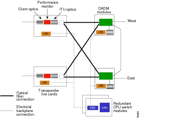
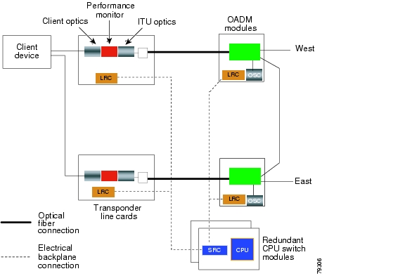
Figure 10-3 shows an example of line card protection using transponder line cards.
Figure 10-3 Client Based Line Card Protection Using Transponder Line Cards
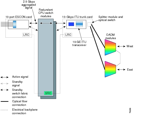
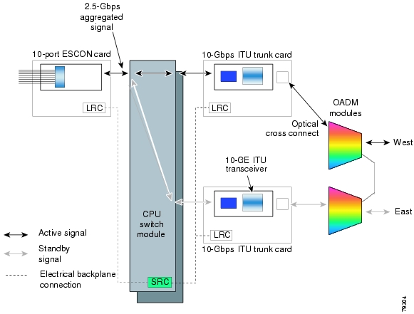
Figure 10-4 shows an example of line card protection using ESCON aggregation cards and 10-Gbps ITU trunk cards.
Figure 10-4 Client Based Line Card Protection Using ESCON Aggregation Cards and 10-Gbps ITU Trunk Cards
About Y-Cable Line Card Protection
With y-cable protection, the client equipment sends only one signal to two transponder line cards or two 8-port FC/GE aggregation cards using a y-cable to replicate the signal. The client equipment receives from only one line card. The Cisco ONS 15530 turns on the laser at the active transparent interface, and turns off the laser on the standby transparent interface. At each receiver on the trunk side of the line card, the system monitors the optical signal power level. If the system detects a failure of the active signal when an acceptable signal exists on the standby line card, a switchover to the standby signal occurs by turning off the active transmitter at the client interface and turning on the standby transmitter.
Figure 10-5 Y-Cable Based Line Card Protection Scheme
Considerations for Using Y-Cable Based Line Card Protection
The following considerations apply when considering the use of line card protection:
•
•
For more information about multiple shelf nodes, see Chapter 11, "Configuring Multiple Shelf Nodes."
•
•
Caution
Proper physical configuration of the system is critical to the operation of line card protection. For detailed information on shelf configuration rules, refer to the Cisco ONS 15530 Planning Guide.
Configuring Y-Cable Based Line Card Protection
The following is an overview of the tasks required to configure line card protection:
Step 1
Step 2
Step 3
Step 4
Step 5
Step 6
Y-cable protection on the Cisco ONS 15530 requires configuration on the CLI. To configure y-cable protection, use the following commands, beginning in global configuration mode:
Caution
Example
This example shows how to associate two transparent interfaces for y-cable line card protection.
Switch# configure terminalSwitch(config)# redundancySwitch(config-red)# associate group YosemiteSwitch(config-red-aps)# aps working transparent 3/0/0Switch(config-red-aps)# aps protection transparent 4/0/0Switch(config-red-aps)# aps y-cableSwitch(config-red-aps)# aps enableSwitch(config-red-aps)# endSwitch#Displaying the Y-Cable Protection Configuration
To display the y-cable protection configuration, use the following EXEC command:
Example
The following example shows how to display the y-cable protection for an APS group:
Switch# show apsAR : APS Role, Wk: Working, Pr: ProtectionAS : APS State, Ac: Active, St: Standby, NA: Not ApplicableIS : Interface State, Up: Up, Dn: DownMPL: Minimum Protection Level, SD: Signal Degrade, SF: Signal FailureLOL: Loss of Light, - not currently protectedInterface AR AS IS MPL Redundant Intf Group Name~~~~~~~~~~~~~~~~~~~~~ ~~ ~~ ~~ ~~~ ~~~~~~~~~~~~~~~~~~~~~ ~~~~~~~~~~~~~~~~~~~~Transparent4/0/0 Wk St Up - Transparent7/0/0 YosemiteTransparent7/0/0 Pr Ac Up SD Transparent4/0/0 YosemiteSwitch# show aps group YosemiteAPS Group Yosemite :architecture.: 1+1, remote prov: 1+1span.........: end-to-endprot. mode...: client side y-cabledirection....: prov: bi, current: bi, remote prov: birevertive....: noaps state....: enabled (associated)request timer: holddown: 5000 ms, max: 15000 ms, count 2msg-channel..: auto (up on osc)created......: 17 hours, 10 minutesauto-failover: enabledtransmit k1k2: reverse-request, 1, 1, 1+1, bireceive k1k2: forced-switch, 1, 1, 1+1, biswitched chan: 1protection(0): Transparent7/0/0 (ACTIVE - UP), Wave7/0 (UP): channel request: no-request: switchover count: 2: last switchover: 15 hours, 14 minutesworking...(1): Transparent4/0/0 (STANDBY - UP), Wave4/0 (UP): channel request: no-request: switchover count: 3: last switchover: 14 hours, 41 minutesAbout Switch Fabric Based Line Card Protection
The Cisco ONS 15530 provides protection for cross connections through the switch fabric. Switch fabric based line card protection is supported on systems with one or two switch fabrics.
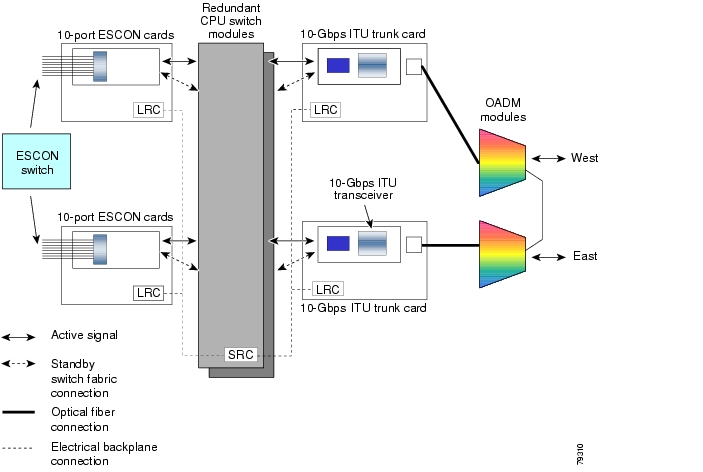
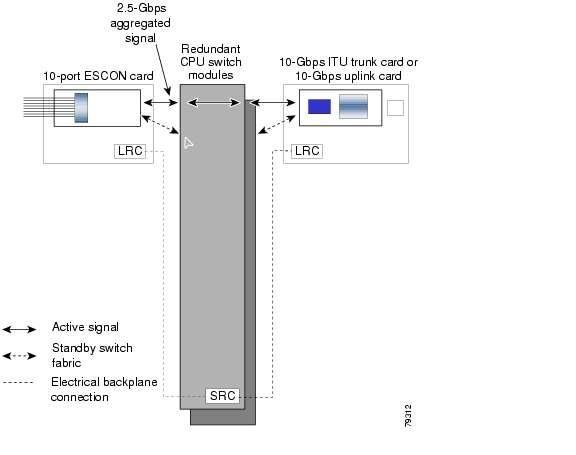
The aggregated signals from the aggregation cards cross connect through the switch fabric to a 2.5-Gbps ITU trunk card, 10-Gbps ITU trunk card, or 10-Gbps uplink card. In switch fabric based line card protection, the system sets up a protection cross connection through the switch fabric to a second 2.5-Gbps ITU trunk card, 10-Gbps ITU trunk card, or a 10-Gbps uplink card (see Figure 10-6).
Figure 10-6 Switch Fabric Based Line Card Protection with Redundant Switch Fabrics
Switch fabric based line card protection protects against facility failures and failures in 2.5-Gbps ITU trunk cards, 10-Gbps ITU trunk cards, and 10-Gbps uplink cards.
Note
Considerations for Using Switch Fabric Based Line Card Protection
The following considerations apply when considering the use of line card protection:
•
•
For more information about multiple shelf nodes, see Chapter 11, "Configuring Multiple Shelf Nodes."
•
•
•
•
Proper physical configuration of the system is critical to the operation of switch fabric based line card protection. For detailed information on shelf configuration rules, refer to the Cisco ONS 15530 Planning Guide.
Configuring Switch Fabric Based Line Card Protection
To configure switch fabric based line card protection, use the following commands:
Note
Note
Displaying Switch Fabric Based Protection Configuration
To display the switch fabric based protection configuration, use the following EXEC command:
show aps [detail | group name | interface {waveethernetphy | tengigethernetphy} slot/subcard]
Displays the APS configuration.
Example
The following example shows how to display the switch fabric based line card protection:
Switch# show aps detailAPS Group yellow :architecture.: 1+1, remote prov: 1+1span.........: end-to-endprot. mode...: switch fabric based line card protectiondirection....: prov: bi, current: bi, remote prov: birevertive....: noaps state....: enabled (associated)request timer: holddown: 5000 ms, max: 15000 ms, count 2msg-channel..: auto-select (up on cdl dcc)created......: 0 minutesauto-failover: enabledtransmit k1k2: no-request, 0, 0, 1+1, bireceive k1k2: no-request, 0, 0, 1+1, biswitched chan: 0protection(0): WaveEthernetPhy8/0 (STANDBY - UP), xc DORMANT: channel request: no-request: switchover count: 0: last switchover: neverworking...(1): WaveEthernetPhy7/0 (ACTIVE - UP), xc UP: channel request: no-request: switchover count: 0: last switchover: neverAbout Trunk Fiber Based Protection
The PSM (protection switch module) provides trunk fiber based protection for Cisco ONS 15530 systems configured in point-to-point topologies. This type of protection only provides protection against trunk fiber cuts, not specific channel failure as provided by splitter and line card based schemes. However, this protection scheme allows for much simpler shelf configurations in topologies where per channel protection is not required.
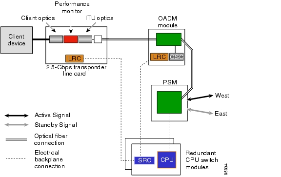
Figure 10-7 shows trunk fiber based protection configured with a transponder line card.
Figure 10-7 Trunk Fiber Based Protection With a Transponder Line Card
Considerations for Using Trunk Fiber Protection
The following considerations apply when using trunk fiber protection:
•
•
•
•
•
•
•
Configuring Trunk Fiber Protection
To configure trunk fiber protection on the wdmsplit interfaces, perform the following steps, beginning in global configuration mode:
Examples
The following example shows how to configure trunk fiber protection:
Switch(config)# redundancySwitch(config-red)# associate group psm-groupSwitch(config-red-aps)# aps working wdmsplit 0/1/0Switch(config-red-aps)# aps protection wdmsplit 0/1/1Switch(config-red-aps)# aps message-channel auto-select far-end group-name psm-groupSwitch(config-red-aps)# aps enableDisplaying Trunk Fiber Protection Configuration
To display the trunk fiber configuration, use the following EXEC command:
show aps [detail | group name | interface wdmsplit slot/subcard/port]
Displays the APS configuration for interfaces and groups.
Note
Examples
The following example shows how to display the protocol encapsulation configuration of a wdmsplit interface:
Switch# show aps group psm-groupAPS Group psm-group :architecture.:1+1, remote prov:unispan.........:end-to-endprot. mode...:network side wdm splitterdirection....:prov:uni, current:uni, remote prov:unirevertive....:noaps state....:enabled (associated)request timer:holddown:5000 ms, max:15000 ms, count 2msg-channel..:auto (down), psm-groupcreated......:2 minutesauto-failover:disabledtransmit k1k2:sf-lp, 0, 0, 1+1, unireceive k1k2:no-request, 0, 0, unknown, unknownswitched chan:0protection(0):WdmSplit0/0/1 (STANDBY - UP):channel request:sf-lp:switchover count:1:last switchover:0 minutesworking...(1):WdmSplit0/0/0 (ACTIVE - UP):channel request:sf-lp:switchover count:1:last switchover:0 minutesAbout Redundant Switch Fabric Protection
The Cisco ONS 15530 provides protection for the 2.5-Gbps aggregated signals sent through the redundant switch fabrics. The switch fabrics connect signals from client side line cards, such as the ESCON aggregation card, to ITU side line cards, such as the 10-Gbps ITU trunk card (see Figure 10-8). When a shelf is configured for CPU switch module redundancy, the redundant switch fabric increases system availability by protecting against switch fabric failures.
Figure 10-8 Redundant Switch Fabrics
Configuring APS Group Attributes
This section describes APS group attributes and how to configure them.
Configuring Revertive Switching
The Cisco ONS 15530 supports revertive switching for all types of protection. When revertive switching is configured, the system automatically switches back from the protection interface to the working interface. This automatic switchover occurs after the condition that caused the switchover to the protection interface is resolved and the switchover-enable timer has expired.
To configure revertive switching, use the following commands, beginning in global configuration mode:
Displaying the Revertive Switching Configuration
To display the revertive switching configuration, use the following EXEC command:
Example
The following example shows how to display the path switching configuration for an APS group named blue:
Switch# show aps group blueAPS Group blue:architecture.: 1+1, remote prov: 1+1span.........: end-to-endprot. mode...: client side y-cabledirection....: prov: uni, current: uni, remote prov: unirevertive....: yes, wtr: 300 secs (not running)
aps state....: enabled (associated)request timer: holddown: 5000 ms, max: 15000 ms, count 2msg-channel..: auto (up on osc)created......: 4 days, 23 hours, 16 minutesauto-failover: enabledtransmit k1k2: no-request, 0, 0, 1+1, unireceive k1k2: no-request, 0, 0, 1+1, uniswitched chan: 0protection(0): Transparent7/0/0 (STANDBY - UP), Wave7/0 (UP): channel request: no-request: switchover count: 2: last switchover: 3 days, 23 hours, 16 minutesworking...(1): Transparent4/0/0 (ACTIVE - UP), Wave4/0 (UP): channel request: no-request: switchover count: 1: last switchover: 4 days, 53 minutesAbout Unidirectional and Bidirectional Path Switching
The Cisco ONS 15530 supports per-channel unidirectional and bidirectional 1+1 path switching. When a signal is protected and the signal fails or degrades on the active path, the system automatically switches the APS group from the active network path to the standby network path.
Signal failures can be total LOL (loss of light) caused by laser failures, by fiber cuts between the Cisco ONS 15530 and the client equipment, between two Cisco ONS 15530s, or by other equipment failures. LOL failures on the transponder line cards and LOLK (loss of lock) on the 2.5-Gbps ITU trunk cards, 10-Gbps ITU trunk cards, and 10-Gbps uplink cards cause switchovers for protected signals.
For y-cable APS, you can also configure alarm thresholds to cause a switchover when the error rate detected on the signal reaches an unacceptable level. For information about configuring alarm thresholds, see the "Configuring Alarm Thresholds" section on page 4-10.
The Cisco ONS 15530 implements path switching using a APS channel protocol over the in-band message channel, the OSC (optical supervisory channel), or the IP management connection.
Note
Figure 10-9 shows a simple point-to-point configuration with splitter protection. The configured working path carries the active signal, and the configured protection path carries the standby signal.
Figure 10-9 Active and Standby Path Configuration Example
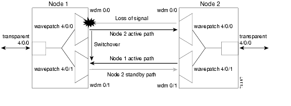
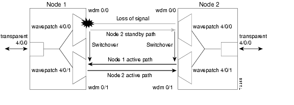
Figure 10-10 shows the behavior of unidirectional path switching when a loss of signal occurs. In the two node example network, unidirectional path switching operates as follows:
•
•
•
•
Now the nodes are communicating along different paths.
Figure 10-10 Unidirectional Path Switching Example
Figure 10-11 shows the behavior of bidirectional path switching when a loss of signal occurs. In the two node example network, bidirectional path switching operates as follows:
•
•
•
•
•
Both node 1 and node 2 communicate on the same path.
Figure 10-11 Bidirectional Path Switching Overview
About APS Switching for Cisco ONS 15216 OADMs
The Cisco ONS 15530 can be connected to Cisco ONS 15216 OADMs in place of native Cisco ONS 15530 OADMs. However, this configuration does not support the Cisco ONS 15530 OSC channel (33rd channel, 1562.23 nm). For bidirectional path switching to function in this configuration, the APS message channel must operate through IP over the NME (Network Management Ethernet) on the CPU switch card. The Ethernet management ports of all the Cisco ONS 15530 and Cisco ONS 15216 systems at the site must connect to a single Ethernet switch, such as the Catalyst 2950, and must be managed over a single VLAN.
Configuring Unidirectional and Bidirectional Path Switching
To configure unidirectional or bidirectional path switching, use the following commands, beginning in global configuration mode:
Step 1
Switch(config)# redundancy
Switch(config-red)#
Enters redundancy configuration mode.
Step 2
Switch(config-red)# associate group name
Switch(config-red-aps)#
Selects the interfaces to associate and enters APS configuration mode.
Note
Step 3
Switch(config-red-aps)# aps disable
Disables APS activity between the interfaces.
Step 4
Switch(config-red-aps)# aps direction {unidirectional | bidirectional}
Specifies the type of path switching. The default behavior is unidirectional.
Step 5
Switch(config-red-aps)# aps timer message holddown milliseconds count number
Changes the APS Channel Protocol holddown timer and message count values. The default is 5000 milliseconds and a count of 2. (Optional)
Step 6
Switch(config-red-aps)# aps timer message max-interval seconds
Changes the APS Channel Protocol maximum interval timer for waiting for a message. The default is 15 seconds. (Optional)
Repeat Step 1 through Step 6 on the corresponding transparent interface on the other node that adds and drops, or terminates, the channel.
Step 7
Switch(config-red-aps)# aps message-channel {auto-select [far-end group-name name] | inband dcc [far-end group-name name] | ip far-end group-name name ip-address ip-address | osc [far-end group-name name]}
Configures the message channel for the APS channel protocol messages. The default is auto-select without a group name. (Optional)
Note
Step 8
Switch(config-red-aps)# aps revertive
Configures revertive path switching. Default is nonrevertive.
Step 9
Switch(config-red-aps)# aps enable
Enables APS activity between the interfaces.
Note
Note
Examples
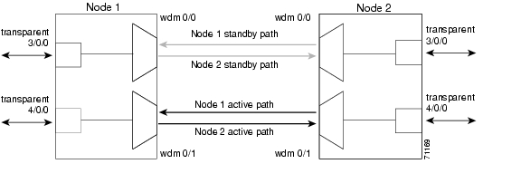
Figure 10-12 shows the active and standby paths between two Cisco ONS 15530 nodes, node 1 and node 2, with splitter protection.
Figure 10-12 Bidirectional Path Switching Example with Splitter Protection
The following example shows how to configure one channel in the example network for bidirectional path switching using the default working and protection path interfaces:
Node1#configure terminalNode1(config)# redundancyNode1(config-red)# associate group redNode1(config-red-aps)# aps working wavepatch 4/0/0Node1(config-red-aps)# aps protection wavepatch 4/0/1Node1(config-red-aps)# aps direction bidirectionalNode1(config-red-aps)# aps enableNode2#configure terminalNode2(config)# redundancyNode2(config-red)# associate group redNode2(config-red-aps)# aps working wavepatch 4/0/0Node2(config-red-aps)# aps protection wavepatch 4/0/1Node2(config-red-aps)# aps bidirectionalNode2(config-red-aps)# aps enableFigure 10-13 shows the active and standby paths between two Cisco ONS 15530 nodes, node 1 and node 2 with y-cable protection.
Figure 10-13 Bidirectional Path Switching Example with Y-Cable Protection
The following example shows how to configure one channel in the example network for bidirectional path switching and configure the working and protection path interfaces:
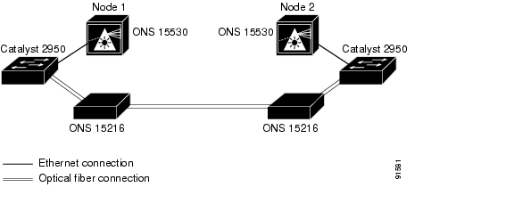
Node1#configure terminalNode1(config)# redundancyNode1(config-red)# associate group alphaNode1(config-red-aps)# aps working transparent 4/0/0Node1(config-red-aps)# aps protection transparent 3/0/0Node1(config-red-aps)# aps direction bidirectionalNode1(config-red-aps)# aps y-cableNode1(config-red-aps)# aps enableNode2#configure terminalNode2(config)# redundancyNode2(config-red)# associate group alphaNode2(config-red-aps)# aps working transparent 4/0/0Node2(config-red-aps)# aps protection transparent 3/0/0Node2(config-red-aps)# aps direction bidirectionalNode2(config-red-aps)# aps y-cableNode2(config-red-aps)# aps enableFigure 10-14 shows the configuration two Cisco ONS 15530 nodes, node 1 and node 2, using Cisco ONS 15216 OADMs and the NME to manage the APS switchovers.
Figure 10-14 Bidirectional Path Switching Example with Cisco ONS 15216 OADMs
The following example shows how to configure one channel in the example network for bidirectional path switching using the NME to manage APS switchovers and configure the working and protection path interfaces:
Node1#configure terminalNode1(config)# interface fastethernet 0Node1(config-if)# ip address 172.16.22.125 255.255.255.0Node1(config-if)# no shutdownNode1(config-if)# exitNode1(config)# redundancyNode1(config-red)# associate group oneNode1(config-red-aps)# aps working transparent 4/0/0Node1(config-red-aps)# aps protection transparent 3/0/0Node1(config-red-aps)# aps direction bidirectionalNode1(config-red-aps)# aps revertiveNode1(config-red-aps)# aps message-channel far-end group-name one ip-address 172.16.22.126Node1(config-red-aps)# aps y-cableNode1(config-red-aps)# aps enableNode1(config-red-aps)# exitNode1#Cat2950-1# configure terminalCat2950-1(config)# interface gigabitethernet 0/1Cat2950-1(config-if)# channel-group 1 mode onCat2950-1(config-if)# exitCat2950-1(config)# interface gigabitethernet 0/2Cat2950-1(config-if)# channel-group 1 mode onCat2950-1(config-if)# exitCat2950-1(config)# interface vlan1Cat2950-1(config-if)# ip address 10.0.0.1 255.255.255.0Cat2950-1(config-if)# endCat2950-1#Node2#configure terminalNode2(config)# interface fastethernet 0Node2(config-if)# ip address 172.16.22.126 255.255.255.0Node2(config-if)# no shutdownNode2(config-if)# exitNode2(config)# redundancyNode2(config-red)# associate group oneNode2(config-red-aps)# aps working transparent 4/0/0Node2(config-red-aps)# aps protection transparent 3/0/0Node2(config-red-aps)# aps direction bidirectionalNode2(config-red-aps)# aps revertiveNode2(config-red-aps)# aps message-channel far-end group-name one ip-address 172.16.22.125Node2(config-red-aps)# aps y-cableNode2(config-red-aps)# aps enableNode2(config-red-aps)# exitNode2#Cat2950-2# configure terminalCat2950-2(config)# interface gigabitethernet 0/1Cat2950-2(config-if)# channel-group 1 mode onCat2950-2(config-if)# exitCat2950-2(config)# interface gigabitethernet 0/2Cat2950-2(config-if)# channel-group 1 mode onCat2950-2(config-if)# exitCat2950-2(config)# interface vlan1Cat2950-2(config-if)# ip address 10.0.0.3 255.255.255.0Cat2950-2(config-if)# endCat2950-2#Displaying the Unidirectional and Bidirectional Path Switching Configuration
To display the path switching configuration, use the following EXEC command:
Example
The following example shows how to display the path switching configuration for an APS group named blue:
Switch# show aps group blueAPS Group blue:architecture.: 1+1, remote prov: 1+1span.........: end-to-endrevertive....: nocreated......: 26 minutesaps state....: associatedtransmit k1k2: reverse-request, 1, 1, 1+1, bireceive k1k2: forced-switch, 1, 1, 1+1, biswitched chan: 0channel ( 0): Wavepatch8/0/1 (STANDBY - UP): channel request: no-request: transmit request: no-request: receive request: no-requestchannel ( 1): Wavepatch8/0/0 (ACTIVE - UP): channel request: no-request: switchover count: 0: last switchover: neverConfiguring the Switchover-Enable Timer
The switchover-enable timer on the Cisco ONS 15530 prevents any automatic switchover from the protection path to the working path until it has expired. When it expires, switchovers occur only if there is no fault on the working path and there is no overriding switchover request in effect.
To configure the switchover-enable timer, use the following commands, beginning in global configuration mode:
Displaying the Switchover-Enable Timer Configuration
To display the switchover-enable timer configuration, use the following EXEC command:
Example
The following example shows how to display the path switching configuration for an APS group named blue:
Switch# show aps group blueAPS Group blue:architecture.: 1+1, remote prov: 1+1span.........: end-to-enddirection....: prov: bi, current: bi, remote prov: birevertive....: yesmsg-channel..: auto (up on osc)created......: 26 minutesaps state....: associatedrequest timer: holddown: 5000 ms, max: 15 secs, count 2transmit k1k2: reverse-request, 1, 1, 1+1, bireceive k1k2: forced-switch, 1, 1, 1+1, biswitched chan: 0channel ( 0): Wavepatch8/0/1 (STANDBY - UP): channel request: no-request: transmit request: no-request: receive request: no-requestchannel ( 1): Wavepatch8/0/0 (ACTIVE - UP): channel request: no-request: switchover count: 0: last switchover: neverAbout Switchovers and Lockouts
In APS, you can switch a channel signal from one path to another, or you can lock out a switchover altogether while performing system maintenance.
A switchover of the channel signal from the working path to protection path is useful when upgrading or maintaining the system, or in cases where a signal failure caused a switchover. The switchover to the formerly failed interface must be requested from the CLI. The interface originally configured as the working path might be preferred because of its link loss characteristics or because of its distance advantage. For example, some protocols, such as ESCON, experience lower data throughput at increasing distances, so moving the signal back to the shorter path might be advised.
A lockout prevents a switchover of the active signal from the working path to the protection path. This is useful when upgrading or maintaining the system, or repairing the protection path when it degrades or fails.
The Cisco ONS 15530 supports APS switchover and lockout requests from the CLI. These requests have priorities depending on the condition of the protection signal and the existence of other switchover requests. There are three types of switchover requests:
•
•
•
In summary, the priority order is:
1.
2.
3.
4.
5.
6.
7.
If a request or condition of a higher priority is in effect, a lower priority request is rejected.
Note
Requesting a Switchover or Lockout
To prevent switchovers to the protection signal, or to request a signal switchover, use the following commands in privileged EXEC mode:
Examples
The following example shows how to request a forced switchover from working to protection except if a lockout is in effect on the protection path:
Switch# aps switch blue force working-to-protectionThe following example shows how to prevent a switchover to the protection path:
Switch# aps lockout blueDisplaying Switchover and Lockout Request Status
To display a pending switchover request, use the following command in privileged EXEC mode:
The following example shows how to display the switchover request status on an APS group:
Switch# show aps group blueAPS Group yellow:architecture.: 1+1, remote prov: 1+1span.........: end-to-end (client side y-cable)direction....: prov: uni, current: uni, remote prov: unirevertive....: nomsg-channel..: auto (up on osc)created......: 15 hours, 1 minuteaps state....: associated (enabled)request timer: holddown: 5000 ms, max: 15000 ms, count 2transmit k1k2: reverse-request, 1, 1, 1+1, bireceive k1k2: forced-switch, 1, 1, 1+1, biswitched chan: 0channel ( 0): Transparent4/0/0 (STANDBY - UP), Wave4/0 (UP): receive request: no-requestchannel ( 1): Transparent2/0/0 (ACTIVE - UP), Wave2/0 (UP): channel request: no-request: switchover count: 0: last switchover: neverClearing Switchovers and Lockouts
A lockout stays in effect until the system reboots. A forced or manual switchover request stays in effect until the system reboots or a higher priority request preempts it. You can manually clear these requests from the CLI.
To clear an APS switchover or lockout request, use the following privileged EXEC command:
aps clear group-name
Clears APS switch request or lockout on an associated interface pair.
Example
The following example shows how to clear the requests on an associated interface pair using the default group name:
Switch# aps clear blueDisplaying Switchover and Lockout Clear Status
To display a pending switchover request, use the following command in privileged EXEC mode:
The following example shows how to display the lockout and switchover request status on an APS group:
Switch# show aps group blueAPS Group blue :architecture.: 1+1, remote prov: 1+1span.........: end-to-end (client side y-cable)direction....: prov: uni, current: uni, remote prov: unirevertive....: nomsg-channel..: auto (up on osc)created......: 15 hours, 1 minuteaps state....: associated (enabled)request timer: holddown: 5000 ms, max: 15000 ms, count 2transmit k1k2: reverse-request, 1, 1, 1+1, bireceive k1k2: forced-switch, 1, 1, 1+1, biswitched chan: 0channel ( 0): Transparent4/0/0 (STANDBY - UP), Wave4/0 (UP): receive request: no-requestchannel ( 1): Transparent2/0/0 (ACTIVE - UP), Wave2/0 (UP): channel request: no-request: switchover count: 0: last switchover: never
![]()
![]()
![]()
![]()
![]()
![]()
![]()
![]()
Posted: Wed Jun 2 13:27:44 PDT 2004
All contents are Copyright © 1992--2004 Cisco Systems, Inc. All rights reserved.
Important Notices and Privacy Statement.