|
|

Table Of Contents
Connector Pinouts
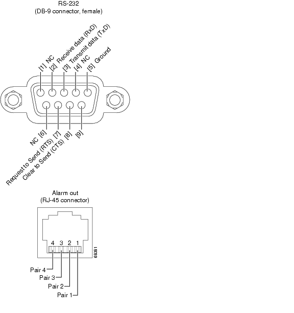
Figure C-1 shows the pin configuration of the RS-232 DB-9 type connector and the Alarm Out RJ-45 connector.
Figure C-1 RS-232 and RJ-45 Connector Pinouts
Pair 1 (pins 1—2): Shorted if LOS exists
Pair 2 (pins 3—4): Shorted if fault exists
Pair 3 (pins 5—6): Shorted if either power supply fails
Pair 4 (pins 7—8): Uncommitted (always shorted)
![]()
![]()
![]()
![]()
![]()
![]()
![]()
![]()
Posted: Thu Jun 24 09:50:22 PDT 2004
All contents are Copyright © 1992--2004 Cisco Systems, Inc. All rights reserved.
Important Notices and Privacy Statement.