|
|

Table Of Contents
Connector Pinouts
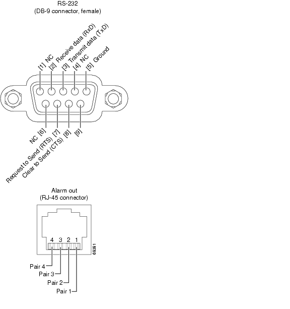
Figure B-1 shows the pin configuration of the RS-232 DB-9 type connector and the Alarm Out RJ-45 connector.
Figure B-1 RS-232 and RJ-45 Connector Pinouts
Pair 1: Loss of input power supply or power supply out of range
Pair 2: Failure in the pump laser bias or pump laser temperature
Pair 3: Loss of input signal or input signal power below threshold
Pair 4: Undefined
![]()
![]()
![]()
![]()
![]()
![]()
![]()
![]()
Posted: Thu Jun 24 10:13:55 PDT 2004
All contents are Copyright © 1992--2004 Cisco Systems, Inc. All rights reserved.
Important Notices and Privacy Statement.