|
|

Product Numbers: WS-C1511=, WS-C1513=, and WS-C1514=
Electrostatic discharge (ESD) can damage equipment and impair electrical circuitry. It occurs when electronic components are improperly handled and can result in complete or intermittent failures. Always follow ESD-prevention procedures when removing and replacing components. Ensure that the chassis is electrically connected to earth ground using an ESD mat or a ground wire. Wear an ESD-preventive wrist strap, ensuring that it makes good skin contact. To safely channel unwanted ESD voltages to ground, connect the clip to the surface of an unpainted chassis frame. To properly guard against ESD damage and shocks, the wrist strap and cord must operate effectively. If no wrist strap is available, ground yourself by touching the metal part of the chassis.
 | Caution For safety, periodically check the resistance value of the antistatic strap, which should be between 1 and 10 mega ohms. |
This publication includes the procedures required to install Copper Distributed Data Interface multilevel transmission (CDDI/MLT-3) and Fiber Distributed Data Interface (FDDI) A/B port cards in the workgroup switch and concentrator models that use this card. The equal sign (=) appended to the product numbers designates these products as spare parts.
Following are the sections and procedures included:
Following are the cabling requirements for the A/B port cards.
The multimode FDDI connectors on the switch accept 62.5/125-micron or 50/125-micron multimode fiber with standard FDDI media interface connectors (MICs). The single-mode connectors accept 8.7 to 10/125-micron single-mode fiber with standard FDDI ST-type connectors. Table 1 lists FDDI distance specifications and Figure 1 and Figure 2 illustrate single-mode and multimode connectors, respectively.
| Transceiver Type | Maximum Distance Between Stations |
|---|---|
| Single-mode | 18.6 miles (up to 30 km) |
| Multimode | 1.2 miles (up to 2 km) |

 | Warning Invisible laser radiation may be emitted from the aperture ports of the single-mode FDDI card when no cable is connected. Avoid exposure and do not stare into open apertures. |

Check all existing cables to ensure that you have the proper connectors (modular RJ-45) and for conformance with the following CDDI/MLT-3 distance requirements and:
When you plan your CDDI installation, remember the following:
The A/B port cards are options that provide two additional CDDI/MLT-3 or FDDI ports.
 | Caution During these procedures, the concentrator must be turned off, thereby disrupting the ring. |
The A/B card slot supports a single media access control (MAC), dual attachment station (DAS) with dual homing configuration for FDDI (can also be used as single attachment station [SAS]). The slot also accepts CDDI/MLT-3 cards for UTP and STP connections.
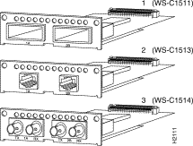
Figure 3 shows the following three models of A/B port cards:

Following is the procedure for installing an A/B port card:
Step 1 Unplug the power cable but, to channel ESD voltages to ground, ground the chassis and attach an ESD-preventive wrist strap.
 | Caution To prevent damage, never install or remove a port card with power applied to the concentrator. |
Step 2 Remove the two screws holding the blank plate to the concentrator and remove the plate.
 | Caution To prevent damage to the FDDI transceivers on the FDDI port card (in step 3), gently press down on the port card as you insert it so that the transceivers clear the chassis. The fit is snug. |
Step 3 Slide the port card into the slot in the concentrator. Make sure the metal base plate on the card slides under the guides in the concentrator. (See Figure 4.)
Step 4 Secure the card to the concentrator using the two Phillips screws supplied with the port card.
Step 5 Reinsert the power cable.

Following is the procedure for removing an A/B port card:
Step 1 Unplug the power cable but, to channel ESD voltages to ground, ground the chassis and attach an ESD-preventive wrist strap.
 | Caution To prevent damage, never install or remove a port card with power applied to the concentrator. |
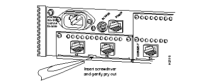
Step 2 Remove the two screws that secure the port card to the concentrator. (See Figure 5.)

 | Caution To prevent damage to the FDDI transceivers on the FDDI port card (in step 3), gently press down on the port card as you remove it so that the transceivers clear the chassis. The fit is snug. |
Step 3 Gently pry the A/B port card out of the slot with a flat-blade screwdriver. (See Figure 5.) After traveling approximately 1/2 inch, the card will be free from the connector and will slide out easily.
Step 4 Reinsert the power cable.


|
|