cc/td/doc/product/lan/cat6000/mod_icn
hometocprevnextglossaryfeedbacksearchhelp
PDF

Table Of Contents

Catalyst 6500 Series Switch WebVPN Services Module Installation and Verification Note

Front Panel Description

Console Port

STATUS LED

FIPS LED

SHUTDOWN Button

System Requirements

Safety Overview

Preparing to Install the WebVPN Services Module

Required Tools

Installing the WebVPN Services Module

Verifying the Installation

Removing the WebVPN Services Module

Related Documentation

Obtaining Documentation

Cisco.com

Product Documentation DVD

Ordering Documentation

Documentation Feedback

Cisco Product Security Overview

Reporting Security Problems in Cisco Products

Obtaining Technical Assistance

Cisco Technical Support & Documentation Website

Submitting a Service Request

Definitions of Service Request Severity

Obtaining Additional Publications and Information


Catalyst 6500 Series Switch WebVPN Services Module Installation and Verification Note


Product number: WS-SVC-WEBVPN-K9

This document provides installation procedures for the Catalyst 6500 series WebVPN Services Module and contains these sections:

Front Panel Description

System Requirements

Safety Overview

Preparing to Install the WebVPN Services Module

Required Tools

Installing the WebVPN Services Module

Verifying the Installation

Removing the WebVPN Services Module

Related Documentation

Obtaining Documentation

Documentation Feedback

Cisco Product Security Overview

Obtaining Technical Assistance

Obtaining Additional Publications and Information

Front Panel Description

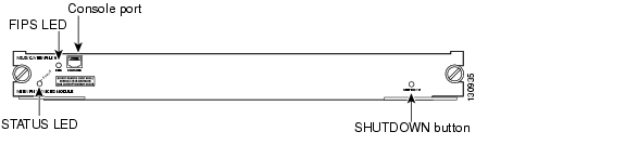
The WebVPN Services Module front panel (see Figure 1) includes a STATUS LED, a Federal Information Processing Standards (FIPS) LED, a SHUTDOWN button, and a console port.

Figure 1 WebVPN Services Module Front Panel

These sections describe the WebVPN Services Module front panel:

Console Port

STATUS LED

FIPS LED

SHUTDOWN Button

Console Port

The console port is used for the inital configuration of the WebVPN Services Module. See the Catalyst 6500 Series Switch WebVPN Services Module Software Configuration Guide for more information on making the inital configuration.


Note The initial WebVPN Services Module configuration must be made through a direct connection to the console port. After the initial configurations, you can make an SSH or Telnet connection to the module to further configure the module.


STATUS LED

The STATUS LED indicates the operating states of the module. Table 1 describes the LED operation.

Table 1 STATUS LED Description 

Color
State
Description

Green

On

All diagnostic tests pass. The module is receiving power.

Red

On

A diagnostic other than an individual port test failed.

Orange

On

Indicates one of three conditions:

The module is running through its boot and self-test diagnostic sequence.

The module is disabled.

The module is in the shutdown state.


Off

The module power is off.


FIPS LED

The FIPS LED currently is not used.

SHUTDOWN Button


Caution Do not remove the WebVPN Services Module from the switch until the module has shut down completely and the STATUS LED is orange. You can damage the module if you remove it from the switch before it completely shuts down.

To avoid corrupting the WebVPN Services Module hard disk, you must correctly shut down the WebVPN Services Module before you remove it from the chassis or disconnect the power. You can shut down the module by entering the hw-mod module mod shutdown command in privileged mode from the router CLI.

If the WebVPN Services Module fails to respond to this command, shut down the module by pressing the SHUTDOWN button on the front panel.

The shutdown procedure may require several minutes. The STATUS LED turns off when the module shuts down.

System Requirements

Before you install the WebVPN Services Module into the Catalyst 6500 series switch, refer to the Release Notes for Catalyst 6500 Series WebVPN Services Module to make sure that the switch meets the hardware and software requirements.

Safety Overview

Safety warnings appear throughout this publication in procedures that, if performed incorrectly, may harm you. A warning symbol precedes each warning statement.

Warning


IMPORTANT SAFETY INSTRUCTIONS

This warning symbol means danger. You are in a situation that could cause bodily injury. Before you work on any equipment, be aware of the hazards involved with electrical circuitry and be familiar with standard practices for preventing accidents. Use the statement number provided at the end of each warning to locate its translation in the translated safety warnings that accompanied this device. Statement 1071

SAVE THESE INSTRUCTIONS


Warning Only trained and qualified personnel should be allowed to install, replace, or service this equipment. Statement 1030


Warning Hazardous voltage or energy is present on the backplane when the system is operating. Use caution when servicing. Statement 1034


Warning Blank faceplates and cover panels serve three important functions: they prevent exposure to hazardous voltages and currents inside the chassis; they contain electromagnetic interference (EMI) that might disrupt other equipment; and they direct the flow of cooling air through the chassis. Do not operate the system unless all cards, faceplates, front covers, and rear covers are in place. Statement 1029


Warning This unit is intended for installation in restricted access areas. A restricted access area can be accessed only through the use of a special tool, lock and key, or other means of security. Statement 1017


Preparing to Install the WebVPN Services Module

Before installing the WebVPN Services Module, make sure that the following items are available:

Catalyst 6500 series switch chassis with Supervisor Engine 720

Management station that is available through a console connection to perform configuration tasks

Required Tools


Warning Only trained and qualified personnel should be allowed to install, replace, or service this equipment. Statement 1030


These tools are required to install the WebVPN Services Module into the Catalyst 6500 series switch:

Flat-blade screwdriver

Wrist strap or other grounding device

Antistatic mat or antistatic foam

Installing the WebVPN Services Module


Note Before installing the WebVPN Services Module, you must install the Catalyst 6500 series switch chassis and at least one supervisor engine. For information on installing the switch chassis, refer to the Catalyst 6500 Series Switch Installation Guide.


This section describes how to install the WebVPN Services Module into the Catalyst 6500 series switch.


Note All modules, including the supervisor engine (if you have redundant supervisor engines), support hot swapping. You can add, replace, or remove modules without interrupting the system power or causing other software or interfaces to shut down. For more information about hot-swapping modules, refer to the Catalyst 6500 Series Switch Module Installation Guide.


Warning During this procedure, wear grounding wrist straps to avoid ESD damage to the card. Do not directly touch the backplane with your hand or any metal tool, or you could shock yourself.


To install the WebVPN Services Module into the Catalyst 6500 series switch, perform these steps:


Step 1 Make sure that you take the necessary precautions to prevent ESD damage.

Step 2 Choose a slot for the WebVPN Services Module. See Figure 2 for the slot numbers on a Catalyst 6500 series switch.

Figure 2 Slot Numbers on Catalyst 6500 Series Switches

Step 3 Check that there is enough clearance to accommodate any interface equipment that you will be connecting directly to the supervisor engine or switching module ports.


Note If possible, place switching modules between the empty slots that contain only switching-module filler plates (Cisco part number 800-00292-01).


Warning Blank faceplates and cover panels serve three important functions: they prevent exposure to hazardous voltages and currents inside the chassis; they contain electromagnetic interference (EMI) that might disrupt other equipment; and they direct the flow of cooling air through the chassis. Do not operate the system unless all cards, faceplates, front covers, and rear covers are in place. Statement 1029


Step 4 Loosen the captive installation screws that secure the switching module filler plate (or an existing switching module) to the desired slot.

Step 5 Remove the switching module filler plate (or an existing switching module).

Step 6 Hold the handle of the WebVPN Services Module with one hand, and place your other hand under the carrier support. Do not touch the printed circuit boards or connector pins.

Step 7 Place the WebVPN Services Module in the slot. Align the notch on the sides of the switching module carrier with the groove in the slot. (See Figure 3.)

Figure 3 Installing Modules in the Catalyst 6500 Series Switch

Step 8 Keep the WebVPN Services Module at a 90-degree angle to the backplane and carefully slide the WebVPN Services Module into the slot until the switching module faceplate contacts the ejector levers. (See  Figure 4 .)

Figure 4 Ejector Levers and Captive Installation Screws

Step 9 Using the thumb and forefinger of each hand, simultaneously push in the left and right levers to fully seat the WebVPN Services Module in the backplane connector.


Caution Always use the ejector levers when installing or removing the WebVPN Services Module. A module that is partially seated in the backplane will cause the system to halt and subsequently crash.


Note If you perform a hot swap, the console displays the message "Module n has been inserted." This message does not appear if you are connected to the Catalyst 6500 series switch through a Telnet session.


Step 10 Use a screwdriver to tighten the captive installation screws on the left and right ends of the WebVPN Services Module.


This completes the WebVPN Services Module installation procedure.

Verifying the Installation

When you install the WebVPN Services Module into the Catalyst 6500 series switch, the module goes through a boot sequence that requires no intervention. At the successful conclusion of the boot sequence, the green STATUS LED will light and remain on. If the STATUS LED is not green, or is a different color, see Table 1 to determine the module's status.

Removing the WebVPN Services Module

This section describes how to remove the WebVPN Services Module from the Catalyst 6500 series switch.


Caution Do not remove the WebVPN Services Module from the switch until the module has shut down completely and the STATUS LED is orange or off. You can damage the module if you remove it from the switch before it completely shuts down.


Warning During this procedure, wear grounding wrist straps to avoid ESD damage to the card. Do not directly touch the backplane with your hand or any metal tool, or you could shock yourself.


To remove the WebVPN Services Module, perform these steps:


Step 1 Shut down the module by one of these methods:

In privileged mode from the router prompt, enter the hw-mod module mod shutdown command.


Note If you enter this command to shut down the module, you will have to enter the following commands in config mode to restart (power down, and then power up) the module:

Router# no power enable module mod
Router# power enable module mod


If the module does not respond to any commands, press the SHUTDOWN button located on the front panel of the module.


Note Shutdown may require several minutes.


Step 2 Verify that the WebVPN Services Module shuts down. Do not remove the module from the switch until the STATUS LED is off or orange.

Step 3 Use a screwdriver to loosen the captive installation screws at the left and right sides of the module.

Step 4 Grasp the left and right ejector levers. Simultaneously, pull the left lever to the left and the right lever to the right to release the module from the backplane connector.

Step 5 As you pull the module out of the slot, place one hand under the carrier to support it. Avoid touching the module itself.

Step 6 Carefully pull the module straight out of the slot, keeping one hand under the carrier to guide it. Keep the module at a 90-degree orientation to the backplane (horizontal to the floor).

Step 7 Place the removed module on an antistatic mat or antistatic foam.


Warning Blank faceplates and cover panels serve three important functions: they prevent exposure to hazardous voltages and currents inside the chassis; they contain electromagnetic interference (EMI) that might disrupt other equipment; and they direct the flow of cooling air through the chassis. Do not operate the system unless all cards, faceplates, front covers, and rear covers are in place. Statement 1029


Step 8 If the slot is to remain empty, install a module filler plate to keep dust out of the chassis and to maintain proper airflow through the module compartment.


Related Documentation

For more detailed installation and configuration information, refer to the following publications:

Release Notes for Catalyst 6500 Series Switch WebVPN Services Module

Catalyst 6500 Series Switch WebVPN Services Module Software Configuration Guide

Catalyst 6500 Series Switch WebVPN Services Module Command Reference

Catalyst 6500 Series Switch WebVPN Services Module System Message Guide

Catalyst 6500 Series Switch Installation Guide

Catalyst 6500 Series Switch Module Installation Guide

Catalyst 6500 Series Switch Software Configuration Guide

Catalyst 6500 Series Switch Command Reference

Catalyst 6500 Series Switch IOS Software Configuration Guide

Catalyst 6500 Series Switch IOS Command Reference

Regulatory Compliance and Safety Information for the Catalyst 6500 Series Switches

Obtaining Documentation

Cisco documentation and additional literature are available on Cisco.com. Cisco also provides several ways to obtain technical assistance and other technical resources. These sections explain how to obtain technical information from Cisco Systems.

Cisco.com

You can access the most current Cisco documentation at this URL:

http://www.cisco.com/techsupport

You can access the Cisco website at this URL:

http://www.cisco.com

You can access international Cisco websites at this URL:

http://www.cisco.com/public/countries_languages.shtml

Product Documentation DVD

Cisco documentation and additional literature are available in the Product Documentation DVD package, which may have shipped with your product. The Product Documentation DVD is updated regularly and may be more current than printed documentation.

The Product Documentation DVD is a comprehensive library of technical product documentation on portable media. The DVD enables you to access multiple versions of hardware and software installation, configuration, and command guides for Cisco products and to view technical documentation in HTML. With the DVD, you have access to the same documentation that is found on the Cisco website without being connected to the Internet. Certain products also have .pdf versions of the documentation available.

The Product Documentation DVD is available as a single unit or as a subscription. Registered Cisco.com users (Cisco direct customers) can order a Product Documentation DVD (product number DOC-DOCDVD=) from the Ordering tool or Cisco Marketplace.

Cisco Ordering tool:

http://www.cisco.com/en/US/partner/ordering/

Cisco Marketplace:

http://www.cisco.com/go/marketplace/

Ordering Documentation

Beginning June 30, 2005, registered Cisco.com users may order Cisco documentation at the Product Documentation Store in the Cisco Marketplace at this URL:

http://www.cisco.com/go/marketplace/

Cisco will continue to support documentation orders using the Ordering tool:

Registered Cisco.com users (Cisco direct customers) can order documentation from the Ordering tool:

http://www.cisco.com/en/US/partner/ordering/

Instructions for ordering documentation using the Ordering tool are at this URL:

http://www.cisco.com/univercd/cc/td/doc/es_inpck/pdi.htm

Nonregistered Cisco.com users can order documentation through a local account representative by calling Cisco Systems Corporate Headquarters (California, USA) at 408 526-7208 or, elsewhere in North America, by calling 1 800 553-NETS (6387).

Documentation Feedback

You can rate and provide feedback about Cisco technical documents by completing the online feedback form that appears with the technical documents on Cisco.com.

You can send comments about Cisco documentation to bug-doc@cisco.com.

You can submit comments by using the response card (if present) behind the front cover of your document or by writing to the following address:

Cisco Systems
Attn: Customer Document Ordering
170 West Tasman Drive
San Jose, CA 95134-9883

We appreciate your comments.

Cisco Product Security Overview

Cisco provides a free online Security Vulnerability Policy portal at this URL:

http://www.cisco.com/en/US/products/products_security_vulnerability_policy.html

From this site, you can perform these tasks:

Report security vulnerabilities in Cisco products.

Obtain assistance with security incidents that involve Cisco products.

Register to receive security information from Cisco.

A current list of security advisories and notices for Cisco products is available at this URL:

http://www.cisco.com/go/psirt

If you prefer to see advisories and notices as they are updated in real time, you can access a Product Security Incident Response Team Really Simple Syndication (PSIRT RSS) feed from this URL:

http://www.cisco.com/en/US/products/products_psirt_rss_feed.html

Reporting Security Problems in Cisco Products

Cisco is committed to delivering secure products. We test our products internally before we release them, and we strive to correct all vulnerabilities quickly. If you think that you might have identified a vulnerability in a Cisco product, contact PSIRT:

Emergencies —  security-alert@cisco.com

An emergency is either a condition in which a system is under active attack or a condition for which a severe and urgent security vulnerability should be reported. All other conditions are considered nonemergencies.

Nonemergencies —  psirt@cisco.com

In an emergency, you can also reach PSIRT by telephone:

1 877 228-7302

1 408 525-6532


Tip We encourage you to use Pretty Good Privacy (PGP) or a compatible product to encrypt any sensitive information that you send to Cisco. PSIRT can work from encrypted information that is compatible with PGP versions 2.x through 8.x.

Never use a revoked or an expired encryption key. The correct public key to use in your correspondence with PSIRT is the one linked in the Contact Summary section of the Security Vulnerability Policy page at this URL:

http://www.cisco.com/en/US/products/products_security_vulnerability_policy.htm

The link on this page has the current PGP key ID in use.


Obtaining Technical Assistance

Cisco Technical Support provides 24-hour-a-day award-winning technical assistance. The Cisco Technical Support & Documentation website on Cisco.com features extensive online support resources. In addition, if you have a valid Cisco service contract, Cisco Technical Assistance Center (TAC) engineers provide telephone support. If you do not have a valid Cisco service contract, contact your reseller.

Cisco Technical Support & Documentation Website

The Cisco Technical Support & Documentation website provides online documents and tools for troubleshooting and resolving technical issues with Cisco products and technologies. The website is available 24 hours a day, at this URL:

http://www.cisco.com/techsupport

Access to all tools on the Cisco Technical Support & Documentation website requires a Cisco.com user ID and password. If you have a valid service contract but do not have a user ID or password, you can register at this URL:

http://tools.cisco.com/RPF/register/register.do


Note Use the Cisco Product Identification (CPI) tool to locate your product serial number before submitting a web or phone request for service. You can access the CPI tool from the Cisco Technical Support & Documentation website by clicking the Tools & Resources link under Documentation & Tools. Choose Cisco Product Identification Tool from the Alphabetical Index drop-down list, or click the Cisco Product Identification Tool link under Alerts & RMAs. The CPI tool offers three search options: by product ID or model name; by tree view; or for certain products, by copying and pasting show command output. Search results show an illustration of your product with the serial number label location highlighted. Locate the serial number label on your product and record the information before placing a service call.


Submitting a Service Request

Using the online TAC Service Request Tool is the fastest way to open S3 and S4 service requests. (S3 and S4 service requests are those in which your network is minimally impaired or for which you require product information.) After you describe your situation, the TAC Service Request Tool provides recommended solutions. If your issue is not resolved using the recommended resources, your service request is assigned to a Cisco engineer. The TAC Service Request Tool is located at this URL:

http://www.cisco.com/techsupport/servicerequest

For S1 or S2 service requests or if you do not have Internet access, contact the Cisco TAC by telephone. (S1 or S2 service requests are those in which your production network is down or severely degraded.) Cisco engineers are assigned immediately to S1 and S2 service requests to help keep your business operations running smoothly.

To open a service request by telephone, use one of the following numbers:

Asia-Pacific: +61 2 8446 7411 (Australia: 1 800 805 227)
EMEA: +32 2 704 55 55
USA: 1 800 553-2447

For a complete list of Cisco TAC contacts, go to this URL:

http://www.cisco.com/techsupport/contacts

Definitions of Service Request Severity

To ensure that all service requests are reported in a standard format, Cisco has established severity definitions.

Severity 1 (S1)—Your network is "down," or there is a critical impact to your business operations. You and Cisco will commit all necessary resources around the clock to resolve the situation.

Severity 2 (S2)—Operation of an existing network is severely degraded, or significant aspects of your business operation are negatively affected by inadequate performance of Cisco products. You and Cisco will commit full-time resources during normal business hours to resolve the situation.

Severity 3 (S3)—Operational performance of your network is impaired, but most business operations remain functional. You and Cisco will commit resources during normal business hours to restore service to satisfactory levels.

Severity 4 (S4)—You require information or assistance with Cisco product capabilities, installation, or configuration. There is little or no effect on your business operations.

Obtaining Additional Publications and Information

Information about Cisco products, technologies, and network solutions is available from various online and printed sources.

Cisco Marketplace provides a variety of Cisco books, reference guides, documentation, and logo merchandise. Visit Cisco Marketplace, the company store, at this URL:

http://www.cisco.com/go/marketplace/

Cisco Press publishes a wide range of general networking, training and certification titles. Both new and experienced users will benefit from these publications. For current Cisco Press titles and other information, go to Cisco Press at this URL:

http://www.ciscopress.com

Packet magazine is the Cisco Systems technical user magazine for maximizing Internet and networking investments. Each quarter, Packet delivers coverage of the latest industry trends, technology breakthroughs, and Cisco products and solutions, as well as network deployment and troubleshooting tips, configuration examples, customer case studies, certification and training information, and links to scores of in-depth online resources. You can access Packet magazine at this URL:

http://www.cisco.com/packet

iQ Magazine is the quarterly publication from Cisco Systems designed to help growing companies learn how they can use technology to increase revenue, streamline their business, and expand services. The publication identifies the challenges facing these companies and the technologies to help solve them, using real-world case studies and business strategies to help readers make sound technology investment decisions. You can access iQ Magazine at this URL:

http://www.cisco.com/go/iqmagazine

or view the digital edition at this URL:

http://ciscoiq.texterity.com/ciscoiq/sample/

Internet Protocol Journal is a quarterly journal published by Cisco Systems for engineering professionals involved in designing, developing, and operating public and private internets and intranets. You can access the Internet Protocol Journal at this URL:

http://www.cisco.com/ipj

Networking products offered by Cisco Systems, as well as customer support services, can be obtained at this URL:

http://www.cisco.com/en/US/products/index.html

Networking Professionals Connection is an interactive website for networking professionals to share questions, suggestions, and information about networking products and technologies with Cisco experts and other networking professionals. Join a discussion at this URL:

http://www.cisco.com/discuss/networking

World-class networking training is available from Cisco. You can view current offerings at this URL:

http://www.cisco.com/en/US/learning/index.html


hometocprevnextglossaryfeedbacksearchhelp

Posted: Wed Sep 7 10:17:05 PDT 2005
All contents are Copyright © 1992--2005 Cisco Systems, Inc. All rights reserved.
Important Notices and Privacy Statement.