|
|

This publication contains the procedures for installing and configuring the Catalyst 6000 family Multilayer Switch Module (MSM). The procedures are arranged in the order that they should be performed. Hardware installation begins in the "Installing the Multilayer Switch Module" section. However, we recommend that you review the prior sections to get an understanding of the MSM.
This publication consists of the following sections:
The Multilayer Switch Module (MSM) provides multiprotocol routing for the Catalyst switch Ethernet interfaces. Table 1 lists the Cisco IOS features available for the MSM.
| 1FIB = forwarding information base
2IGRP = Interior Gateway Routing Protocol 3EIGRP = Enhanced Interior Gateway Routing Protocol 4OSPF = Open Shortest Path First 5RIP = Routing Information Protocol 6PIM = Protocol Independent Multicast 7DVMRP = Distance Vector Multicast Routing Protocol 8IGMP = Internet Group Management Protocol 9CGMP = Cisco Group Multicast Protocol 10ICMP = Internet Control Message Protocol 11GDP = Gateway Discovery Protocol 12IRDP = ICMP Router Discovery Protocol 13IRB = Integrated Routing and Bridging 14DNS = Domain Naming System 15DHCP = Dynamic Host Configuration Protocol 16BOOTP = Boot Protocol 17M-HSRP = Multiple-Hot Standby Routing Protocol 18CDP = Cisco Discovery Protocol 19QOS = Quality of Service 20COS = Class of Service 21VC = virtual circuit |
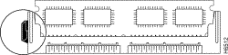
The MSM front panel features are shown in Figure 1 and are described in the following sections.

When the MSM is powered up, it initializes various hardware components and communicates with the supervisor engine. The Status LED shows the results of the initialization and its dialogue with the supervisor engine, as described in Table 2.
Note For detailed information on the supervisor engine LEDs, refer to the Catalyst 6000 and 6500 Series Supervisor Engine Installation Guide.
| 1If the module is listed by the supervisor engine as faulty in the show module status field, enter the show test mod_num command to see the details of any test failure.
2CLI = command-line interface. 3Enter the show temperature command from the MSM router prompt to display current temperature, major and minor thresholds, and the number of alarms that have occurred since the last system boot. Enter the show environment temperature mod_num command from the Catalyst switch prompt to display the temperature of each of four sensors on the MSM. |
MSM Status LED
The console port mode switch allows you to connect a terminal to the MSM using either a
Catalyst 5000 series Supervisor Engine III console cable or the console cable and adapters provided with a Catalyst 6000 family switch. Additionally, you can connect a modem to the console port using the cable and adapter provided with the switch.
Use the port mode switch as follows:
You can also use this mode to connect a modem to the console port using the console cable and data communications equipment (DCE) adapter (labeled "Modem") that shipped with the switch.
Note You should not have to connect a terminal to the MSM console port. When your terminal is connected to the supervisor engine console port, use the session command to access the MSM for router configuration.
The console port allows you to access the MSM either locally (with a console terminal) or remotely (with a modem). The console port is an EIA/TIA-232 asynchronous, serial connection with an RJ-45 connector.
Note EIA/TIA-232 and EIA/TIA-449 were known as recommended standards RS-232 and RS-449 before their acceptance as standards by the Electronic Industries Association (EIA) and Telecommunications Industry Association (TIA).
Note The accessory kit that shipped with your Catalyst 6000 family switch contains the cable and adapters to connect a terminal or modem to the console port. These cables and adapters are the same as those shipped with the Cisco 2500 series routers and other Cisco products.
Note For complete console port cabling specifications and pinouts, refer to the Catalyst 6000 and 6500 Series Supervisor Engine Installation Guide.
To connect a terminal to the console port using the cable and adapters provided with the
Catalyst 6000 family switch, ensure that the console port mode switch is in the in position (factory default position). Connect to the port using the RJ-45-to-RJ-45 cable and RJ-45-to-DB-25 DTE adapter or RJ-45-to-DB-9 DTE adapter (labeled "Terminal").
To connect a terminal using a Catalyst 5000 series Supervisor Engine III console cable, place the console port mode switch in the out position. Connect to the port using the Catalyst 5000 series Supervisor Engine III cable and the appropriate adapter for the terminal connection.
Check the documentation that came with your terminal to determine the baud rate. The baud rate of the terminal must match the default baud rate (9600 baud) of the console port. Set up the terminal as follows:
To connect a modem to the console port, ensure that the console port mode switch is in the in position (factory default position). Connect the modem to the port using the RJ-45-to-RJ-45 cable and the RJ-45-to-DB-25 DCE adapter (labeled "Modem").
This section describes the basic operation of the MSM and introduces concepts necessary to configure the MSM.
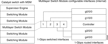
The MSM runs Cisco IOS router software that directly interfaces to (plugs into) the switch backplane to provide Layer 3 switching (see Figure 2).
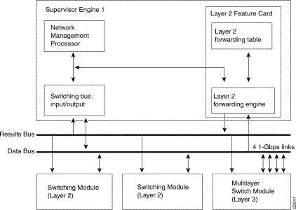
The MSM connects to the switching bus through four full-duplex Gigabit Ethernet interfaces. The Catalyst switch sees the MSM as an external router connected to the switch through the four interfaces. You can group the four Gigabit interfaces into a single Gigabit EtherChannel or configure them as independent interfaces (links). If channeled, the channel supports trunking through 802.1Q or ISL. Once you configure a channel and specify a trunk type, the port-channel interface on the MSM is configured with one subinterface for every VLAN on the switch—providing interVLAN routing. Alternatively, you can configure each Gigabit interface (link) independently as a separate VLAN trunk or nontrunked routed interface.
Note The supervisor engine software sees each Gigabit interface as a configurable port. For example, if the MSM is installed in slot 4 and you enter the show module 4 command, you will see ports 4/1, 4/2, 4/3, and 4/4. Similarly, the MSM software sees each Gigabit interface as a configurable interface. For example, if you do a show interface from the MSM, you see interfaces g0/0/0, g1/0/0, g3/0/0, and g4/0/0 (there is no g2/0/0). Configuration procedures are provided in the "Configuring the Multilayer Switch Module for InterVLAN Routing" section.
Each full-duplex Gigabit Ethernet interface to the Catalyst switching bus is assigned a MAC address; 1024 MAC addresses are available for MSM subinterfaces.
Hot swapping lets you remove and replace the MSM while the system is operating. When the system detects that a module has been installed or removed, it automatically runs diagnostic and discovery routines, acknowledges the presence or absence of the module, and resumes system operation without any user intervention.
Note The 1000W power supply is used in the six-slot chassis; the 1300W supply is used in the nine-slot chassis. Do not use the 1000W supply in the nine-slot chassis.
Because the Catalyst 6000 and 6500 series modules have different power requirements, certain switch configurations require more power than a single power supply can provide. Although the power management feature allows you to power all installed modules with two power supplies, redundancy is not supported in this configuration. Loss of power redundancy (and the need for more than one supply) is only an issue when you are using two MSMs.
When operating a nine-slot chassis with power redundancy (or a single supply), the only limitations with two MSMs are that you are limited to five 10/100 modules and cannot have a 1000BaseX Gigabit Interface Converter (GBIC) module in the remaining slot, as shown in Table 3. Redundant and nonredundant power configurations are discussed in the following sections. You can change the configuration of the power supplies at any time.
When operating a six-slot chassis with power redundancy (or a single supply), there are no limitations with two MSMs; the chassis supports two MSMs and any combination of additional modules.
If you have two power supplies of equal wattage installed, you can configure them in a redundant configuration. Use the set power redundancy enable | disable command to enable or disable redundancy. In a redundant configuration, the total power drawn from both supplies is at no time greater than the capability of one supply. If one supply malfunctions, the other supply can take over the entire system load. When you install and turn on two power supplies, each concurrently provides approximately half of the required power to the system. Load sharing and redundancy are enabled automatically; no software configuration is required.
In a nonredundant configuration, the power available to the system is the combined power capability of both power supplies. The system powers up as many modules as the combined capacity allows.
For more information on power management, refer to the Catalyst 6000 and 6500 Series Supervisor Engine Installation Guide.
Table 3 Possible Switch Configurations with Two MSMs
| Switch Slots | Switch Configuration | |||||
|---|---|---|---|---|---|---|
| 1The WS-X6248-RJ-TEL (10/100) has the same power consumption as WS-X6248-RJ-45 (10/100).
2Any module = WS-X6224-100FX-MT (100FX) or WS-X6408-GBIC (1000BaseX). 3Or a redundant supervisor engine in slot 2 (that is, two supervisor engines, two MSMs, and five 10/100 modules). |
Environmental monitoring of chassis components provides early warning indications of possible component failure to ensure safe and reliable system operation and avoid network interruptions. For detailed information on environmental monitoring, refer to the Catalyst 6000 and 6500 Series Supervisor Engine Installation Guide.
If you manage the MSM directly through a Gigabit Ethernet routing port, any IP address assigned to the corresponding interface can be used for network management purposes provided the port is up.
The supervisor engine reports one IP address assigned to the MSM that can be used for network management through the Cisco Stacks MIB. This section describes how this IP address is selected by the MSM.
The MSM randomly selects an IP address that has been assigned to one of the Gigabit Ethernet switched ports or port channels as the network management IP address, provided the interface or subinterface associated with this IP address is up at the time of selection.
If the selected network management IP address is removed or the interface or subinterface associated with this IP address is shut down, the MSM selects another IP address as a replacement.
If all the interfaces are down or no IP address has been assigned to any interface or subinterface that is up, the IP address for network management is 0.0.0.0.
After each IP address selection or change of the IP address, the MSM sends an unsolicited message to the supervisor engine which then populates the IP address attribute of the Cisco Stacks MIB entry of the MSM.
Use the show net-management command from the MSM router prompt to display the current IP address for network management.
Access lists (ACLs) are supported for routing protocol distribution lists, route-maps, and access lists for control traffic or traffic that is forwarded to the route processor on the MSM (these ACLs are known as control plane ACLs). The MSM does not support access lists for user traffic meant to traverse through it forwarded by the Catalyst 6000 family switching modules (these ACLs are known as data plane ACLs).
Catalyst 6000 family switches with the MSM support MLS server (not client).
Slot 1 on the Catalyst 6000 and 6500 series switch is reserved for the supervisor engine. If you are using a redundant supervisor engine, it would go in slot 2; otherwise, slot 2 can be used for other modules. The MSM can be installed in any of the remaining slots.
| Caution When removing or inserting a module, always wear an electrostatic discharge (ESD) wrist strap connected to the Catalyst 6000 and 6500 series switch ESD wrist strap connector. |
Follow these steps to install the MSM:
Note You do not need to connect a terminal to the MSM console port. At the end of the installation procedure, use the session command to access the MSM for router configuration.
Step 2 Use a screwdriver to loosen the two captive installation screws and remove the module filler plate or the existing module from the slot you want to use.
Step 3 Guide the MSM into the slot, aligning the sides of the MSM with the guides in the slot (avoid touching the components on the board).
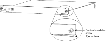
Step 4 While keeping the module oriented horizontally, carefully slide it into the slot until its front panel contacts the ejector levers (see Figure 3).
Step 5
![]()
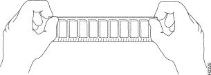
Using the thumb and forefinger of each hand, simultaneously push the left lever and the right lever in to seat the module all the way into the backplane connector.
Step 6 Use a screwdriver to tighten the captive installation screws on the left and right sides of the module (see Figure 3).
Step 7 Check the status of the module as follows:
Step 8 After verifying that the MSM is operational, enter the session mod/num command (mod/num is the MSM slot number) at the Cat6000> prompt. You should now be at the router> prompt. Proceed to the "Booting the Multilayer Switch Module for the First Time" section.
The MSM is configured at the factory to load a Cisco IOS image (router operating system software) automatically the first time you power on (insert) the MSM into a Catalyst 6000 family switch. The MSM software configuration register, which determines where the MSM loads the image from, is set at the factory to load the image from bootflash (configuration register setting 0x0101). Table 4 shows the MSM default configuration.
Table 4 MSM Default Configuration
| Feature | Default Value |
After the MSM goes through power-on self-test diagnostics, and the front panel Status LED is green, you can access the MSM by entering the session mod/num command at the Cat6000> prompt—this gets you to the router> prompt.
After booting the MSM for the first time, you need to configure the MSM internal interfaces and then save the configuration to a file in NVRAM. Configuration guidelines and procedures are provided in the "Configuring the Multilayer Switch Module for InterVLAN Routing" section.
These sections describe basic router configuration tasks you need to understand before you configure interVLAN routing:
To access configuration mode on the router, perform this task:
| Task | Command |
|---|---|
| Step 1. At the EXEC prompt, enter enable mode. | |
| Step 2. At the privileged EXEC prompt, enter global configuration mode. | |
| Step 3. Enter the commands to configure interVLAN routing. | See the "Configuring the Multilayer Switch Module for InterVLAN Routing" section. |
| Step 4. Exit configuration mode. |
To view and save the configuration after you make changes, perform this task:
| Task | Command |
|---|---|
| Step 1. View the current operating configuration at the privileged EXEC prompt. | |
| Step 2. View the configuration in NVRAM. | |
| Step 3. Save the current configuration to NVRAM. |
In some cases, a router interface might be administratively shut down. You can check the status of an interface using the show interface command.
To bring up a router interface that is administratively shut down, perform this task in privileged mode:
| Task | Command |
|---|---|
| Step 1. Specify the interface to bring up. | |
| Step 2. Bring the interface up. | |
| Step 3. Exit configuration mode. |
| Task | Command |
|---|---|
| Step 1. Specify a password. | |
| Step 2. Exit configuration mode. | |
| Step 3. Save the current configuration to NVRAM. |
To assign a privileged mode password, perform this task:
These sections describe how to configure the MSM for interVLAN routing:
Note Acquire the correct network addresses, such as IP addresses for the MSM interfaces, from your system administrator, or consult your network plan to determine correct addresses before you begin to configure the MSM.
As discussed in the "Functional Description" section, the MSM appears to the
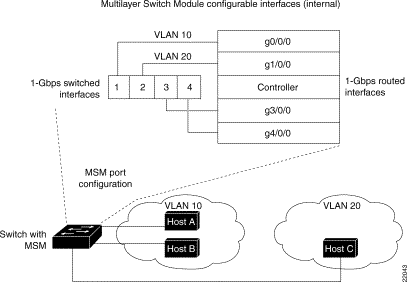
Catalyst switch as an external router connected to the switch through four full-duplex Gigabit Ethernet ports. Conversely, the Catalyst switch appears to the MSM as a four-port Gigabit Ethernet module (see Figure 4). Port 1 on the Catalyst switch side is connected to interface g0/0/0 on the MSM side, port 2 to interface g1/0/0, port 3 to interface g3/0/0, and port 4 to interface g4/0/0.
There are two initial configuration options for the Gigabit switched and routed interfaces—channel the interfaces or configure them as independent links. These options are described in the "Configuration Guidelines" section.
Network devices in different VLANs cannot communicate with one another without a router to route traffic between the VLANs. In most network environments, VLANs are associated with individual networks or subnetworks.
For example, in an IP network, each subnetwork is mapped to an individual VLAN. In an IPX network, each VLAN is mapped to an IPX network number.
VLANs help to control the size of the broadcast domain and keep local traffic local. However, when an end station in one VLAN needs to communicate with an end station in another VLAN, interVLAN communication is required. This communication is supported by interVLAN routing. You configure one or more routers to route traffic to the appropriate destination VLAN.
Figure 5 shows a basic interVLAN routing topology using the MSM. Host A and Host B are in VLAN 10 and Host C is in VLAN 20. The MSM has an interface in each VLAN.
When Host A in VLAN 10 needs to communicate with Host B in VLAN 10, it sends a packet addressed to that host. The switch forwards the packet directly to Host B, without sending it to the router.
When Host A sends a packet to Host C in VLAN 20, the switch forwards the packet to the router, which receives the traffic on the VLAN 10 interface. The router checks the routing table, determines the correct outgoing interface, and forwards the packet out the VLAN 20 interface to Host C.
To configure the MSM for interVLAN routing, you must first configure VTP and create and configure VLANs on the switch.
Note This section describes the basics of VTP and VLAN configuration. For detailed information on configuring VTP and VLANs, refer to the Catalyst 6000 and 6500 Series Software Configuration Guide.
To configure VTP and VLANs on the switch, perform this task in privileged mode:
This example shows how to configure VTP, create two VLANs, and assign switch ports to those VLANs:
Note The MSM supports VLAN numbering from 1 to 1000 and can be configured with a maximum of 250 subinterfaces each representing a VLAN interface.
As discussed in the "Functional Description" section, you should view the MSM as an external router with four full-duplex Gigabit Ethernet interfaces. The recommended configuration is to group the four Gigabit Ethernet interfaces into a port-channel and then create subinterfaces on the port-channel. The other configuration option is to configure the interfaces independently. The following sections describe both options. Also included, is a description of the autostate feature.
This section describes how to configure a Gigabit Ethernet interface independently on the MSM to provide Layer 3 (routed) gateway services. The physical routed interface can provide Layer 3 gateway services to one or more VLANs. When providing Layer 3 gateway services for one VLAN on the interface, VLAN trunking is not necessary and the MSM Gigabit interface need only be included in the specific VLAN, just as you would include a host port. After adding the MSM interface, you need to assign an IP (or IPX) address to the corresponding MSM routed interface (g0/0/0, g1/0/0, g3/0/0, or g4/0/0).
To provide Layer 3 gateway services for more than one VLAN on an MSM Gigabit interface, you must use VLAN trunking. You can use either of two VLAN trunking methods to create the trunk between the MSM interface and the switch: ISL or 802.1Q.
Although you can use either trunking method, you must use ISL in situations where nonroutable protocols such as local-area transport (LAT) and NetBIOS Extended User Interface (NetBEUI) must be bridged between VLANs. After creating a VLAN trunk between the MSM Gigabit interface and a Catalyst 6000 family switch, you configure subinterfaces on the MSM interface to create Layer 3 (routed) gateways for multiple VLANs.
This section describes how to channel the Gigabit Ethernet interfaces on the MSM using Gigabit EtherChannel to provide Layer 3 (routed) gateway services.
This option involves combining the four Gigabit interfaces into a single Gigabit EtherChannel. Once the EtherChannel is created between the MSM and a Catalyst 6000 family switch, you can configure the channel to provide Layer 3 gateway services to one or multiple VLAN interfaces (the configuration of the VLAN interfaces is identical to the method described in option 1 when trunking is enabled on an independent interface).
While both option 1 and option 2 provide the same service—a routed interface per VLAN on the MSM—option 2 provides a simpler implementation and configuration. By bundling the four MSM Gigabit interfaces into one logical port-channel interface, you can configure Layer 3 VLAN gateways by creating multiple subinterfaces on the same logical interface. Creating subinterfaces on one logical interface is less complicated than manually distributing VLANs among multiple physical and logical interfaces on the MSM.
The autostate feature shuts down (or brings up) MSM interfaces/subinterfaces when the following port configuration changes occur on the switch:
Use the show autostate entries command to see what MSM interfaces are currently autostated (shutdown or brought up through autostate):
It is important to note that the Catalyst switch does not have knowledge of, or control over, the MSM configuration (just as the Catalyst switch does not have knowledge of, or control over, external router configurations). Due to this, the autostate feature will not work on MSM interfaces if the MSM is not properly configured. For example, consider the following MSM trunk configuration:
The GigabitEthernet0/0/0.200 interface will not be autostated if any of the following configuration errors are made:
This section describes how to configure the Gigabit Ethernet switched and routed interfaces on the MSM:
This procedure shows you how to route between four VLANs. VLANs 4, 5, 6, and 7 are configured on a Catalyst 6000 family switch. Trunking is not enabled on any interface as there is just one VLAN on each physical interface. Perform the following steps (in this procedure the MSM is in slot 4):
Step 2 Use the session mod_num command to session to the router prompt:
Step 3 Assign an IP address and subnet mask (or IPX address) to the corresponding routed interface (g0/0/0, g1/0/0, g3/0/0, and g4/0/0).
This procedure shows you how to channel the four Gigabit Ethernet switched and routed interfaces and then enable VLAN trunking on the channel. Subinterfaces can then be configured on the channel interface. You configure a subinterface for each allowed VLAN configured on the MSM trunk. For each subinterface, you specify the type of trunking (same as specified on the channel) and then assign an IP address and subnet mask (or IPX address).
Perform the following steps to channel the interfaces (in this procedure the MSM is in slot 4):
Step 2 Use the set trunk mod_num/port_num command to enable trunking and specify an encapsulation type on the EtherChannel ports (specifying this on one of the EtherChannel ports enables trunking and the specified encapsulation on all ports in the channel):
Step 3 Use the session mod_num command to session to the router prompt:
Step 4 Create an EtherChannel (port-channel) interface (the channel number can be from
1 to 64):
Step 5 Assign the g0/0/0, g1/0/0, g3/0/0, and g4/0/0 interfaces to the port-channel:
Repeat this step on the remaining interfaces.
Step 6 Configure subinterfaces on the port-channel interface, one for each allowed VLAN configured on the MSM trunk for which you want to route (specify the same type of encapsulation as in Step 2):
Repeat this step to create and configure additional subinterfaces on the port-channel.
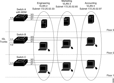
Figure 6 shows an interVLAN routing configuration example. The example shows three switches, one with an MSM installed in slot 5. The switches are connected through the Gigabit Ethernet uplink ports on the supervisor engines. Each switch has a 10/100-Mbps Fast Ethernet module in slot 3. Three hosts are connected to each switch on ports 3/1, 3/2, and 3/3.
You must perform these configuration tasks to configure the network in this example:
1. Configure Switch A as a VTP server and assign a VTP domain name.
2. Configure Switch B and Switch C as VTP clients and assign the same VTP domain name.
3. Configure ISL trunk links between the switches.
4. Create the VLANs on Switch A (the VLAN information is propagated to Switch B and Switch C through VTP).
5. Assign the switch ports on each switch to the appropriate VLAN.
6. On the MSM, assign IP addresses to g0/0/0, g1/0/0, and g3/0/0.
After you successfully configure the network, all end stations should be able to communicate with one another. Communication between hosts in the same VLAN is handled only by the switches. All interVLAN traffic must be routed by the MSM.
For example, if the VLAN 2 host on Floor 1 needs to communicate with the VLAN 3 host on Floor 1, the traffic must travel through all three switches to reach the MSM, where it is routed and sent back through all three switches to the destination host.
This example shows how to configure Switch A:
This example shows how to configure Switch B:
This example shows how to configure Switch C:
This example shows how to configure the MSM:
This section briefly describes how to configure the MSM for each IP routing protocol that it supports. It is intended to provide enough information for any network administrator to get the protocols up and running. However, note that this configuration section is not intended to provide in-depth configuration for each protocol. For such information, please see any of the protocol configuration guides in the public domain.
IP routing is enabled by default on the MSM. The selection of IP as a routing protocol requires that you set both global and interface parameters.
To configure the interface, assign network and subnetwork addresses and the appropriate IP subnet mask.
The MSM supports these routing protocols:
IGRP is a distance vector interior-gateway protocol developed by Cisco Systems. Distance vector routing protocols call for each other to send all or a portion of its routing table in a routing update message at regular intervals to each neighboring router. As routing information proliferates through the network, routers can calculate the distance to all the nodes within the internetwork. IGRP uses a combination of metrics: internetwork delay, bandwidth, reliability, and load are all factored into the routing decision.
An enhanced version of IGRP that combines the advantages of link-state protocols with distance vector protocols. EIGRP incorporates the Diffusing Update Algorithm (DUAL). EIGRP includes features such as fast convergence, variable-length subnet masks, partial bounded updates, and multiple network-layer support.When a network topology change occurs, EIGRP checks its topology table for a suitable new route to the destination. If such a route exists in the table, EIGRP updates the routing table instantly.You can use the fast convergence and partial updates EIGRP provides to redistribute IPX route information.
EIGRP saves WAN-link bandwidth by sending routing updates only when routing information changes. The updates contain information only about the link that changed, not the entire routing table. EIGRP also takes into consideration the available bandwidth when determining the rate at which it transmits updates.
OSPF is a standards-based IP routing protocol designed to overcome the limitations of IP RIP. Because OSPF is a link-state routing protocol, it sends link-state advertisements (LSAs) to all other routers within the same hierarchical area. Information on attached interfaces, metrics used, and some other information is used in OSPF LSAs. As routers accumulate link-state information, they use the Shortest Path First (SPF) algorithm to calculate the shortest path to each node. Additional OSPF features include equal-cost multipath routing and routing based on the upper-layer type of service (ToS) requests.
OSPF employs the concept of an area, which is a grouping of contiguous OSPF networks and hosts. OSPF areas are logical subdivisions of OSPF autonomous systems whose internal topology is hidden to routers outside the area. Areas allow an additional level of hierarchy different from that provided by IP network classes, and they can be used to aggregate routing information and mask the details of a network. These features make OSPF particularly scalable to large networks.
RIP is a distance-vector, intradomain routing protocol. RIP works well in small, homogeneous networks. However, in larger, more complex internetworks RIP has many limitations, such as a maximum hop count of 15, lack of support for variable-length subnet masks (VLSMs), inefficient use of bandwidth, and slow convergence.
Configure each of these routing protocols as follows (you need to configure only those protocols that you run on your network):
Once IP routing is configured, you can monitor and troubleshoot the protocol's operation using the commands shown in Table 5.
Table 5 Verifying IP Operation
Cisco's implementation of Novell's proprietary IPX protocol provides all of the functionality of a Novell "External Bridge" (Novell refers to their router functionality as bridging).
IPX uses these protocols and services:
The NetWare protocol stack is compatible with the Open Data-Link Interface (ODI) and all common media access protocols.
An IPX network address consists of a network number and a node number, expressed in the format network.node.
The network number is a 4-byte (32-bit) number that identifies the physical network. The network number is expressed in hexadecimal and must be unique throughout the entire IPX internetwork. When configuring an IPX network number, you can omit the leading zeros.
The node number identifies a node on the network. It is a 48-bit number, represented by dotted triplets of 4-digit hexadecimal numbers. The node number is normally the MAC address of the NetWare node or router interface.
Since both the network number and the host address are needed to deliver traffic to a host, addresses are usually given as network numbers, followed by host addresses, separated with dots, as in the example: 4a.0000.0c00.23fe. In this example, the network number is 4a, and the host address is 0000.0c00.23fe.
The serial interface does not have a MAC address. It uses the default Novell node address, which is the MAC address of the first activated interface.
To configure IPX as a routing protocol, you must configure both global and interface parameters. The global configuration tasks are as follows:
Load sharing is the even division of routing tasks among multiple routers to balance the work and improve network performance. The MSM supports up to two parallel paths, with a default of one.
The interface configuration tasks are:
You can assign multiple network numbers to an interface, allowing support of different encapsulation types. The IPX network number is the number of the Novell network to which the interface is attached. IPX packets received on an interface that does not have a network number are ignored.
The default encapsulation type for the MSM is novell-ether (Ethernet_802.3).
Note This section does not describe IPX configuration in detail. Please see the IPX documentation on the Cisco Documentation CD for detailed conceptual and configuration information.
The argument number is the number of the Novell network to which that interface is attached. Novell packets received on an interface that does not have a Novell network number are ignored.
Once IPX routing is configured, you can monitor and troubleshoot the protocol's operation using the commands shown in Table 6.
Table 6 Verifying IPX Operation
Note If the MSM is not configured for IP multicast routing and it receives a multicast packet, the packet goes to the MSM CPU which severely affects system performance. To prevent this, enable IGMP on the switch using the set igmp enable command. With IGMP enabled, the MSM does not receive multicast packets that it cannot process.
As networks increase in size, multicast routing becomes critically important as a means to determine which segments require multicast traffic and which do not. IP multicast is a routing technique that allows IP traffic to be propagated from one source to a number of destinations, or from many sources to many destinations. Rather than sending one packet to each destination, one packet is sent to the multicast group identified by a single IP destination group address.
IP multicast routing arose because unicast and broadcast techniques do not effectively handle the requirements of new applications. In addition, multicast addressing supports transmission of a single IP datagram to multiple hosts.
A principal component of IP multicast is the Internet Group Membership Protocol (IGMP). With IGMP, a class D address is used to dynamically register an individual host in a multicast group. Hosts identify their group membership by sending IGMP messages to the MSM. Traffic is sent to all members of a multicast group. A host can be a member of more than one group at a time. Also, a host does not need to be a member of a group to send data to that group. Enabling Protocol Independent Multicast (PIM) on an interface also enables IGMP operation on that interface.
The routing protocols the MSM uses to discover multicast groups and build routes for each group are:
The MSM supports interoperability with routers configured for DVMRP.
PIM includes two different modes of behavior for dense and sparse traffic environments. These are referred to as dense mode and sparse mode.
Dense mode assumes that the downstream networks want to receive the datagrams forwarded to them. The MSM forwards all packets on all outgoing interfaces until pruning and truncation occurs. Interfaces with dense mode enabled receive the multicast data stream until it times out. Dense mode is most useful under these conditions:
Sparse mode assumes that the downstream networks do not want to forward multicast packets for a group unless there is an explicit request for the traffic. Sparse mode defines a rendezvous point, which is used as a registration point to facilitate the proper routing of packets.
When a sender wants to send data, it first sends the data to the rendezvous point. When a router is ready to receive data, it registers with the rendezvous point. After the data stream begins to flow from the sender to the rendezvous point and then to the receiver, routers in the data path optimize the path by automatically removing any unnecessary hops, including the rendezvous point.
Sparse mode is optimized for environments in which there are many multipoint data streams and each multicast stream goes to a relatively small number of LANs in the internetwork. Sparse mode is most useful under these conditions:
Configure IP multicast routing as follows:
Once IP multicast routing is configured, you can monitor and troubleshoot its operation using the commands shown in Table 7.
Table 7 Verifying IP Multicast Operation
Note If you configure bridging between the MSM subinterfaces, you must use ISL trunking on the link to the Catalyst switch. Bridging is not supported using 802.1Q trunking.
Cisco IOS software supports transparent bridging for Ethernet. In addition, Cisco supports all the mandatory Management Information Base (MIB) variables specified for transparent bridging in RFC 1286.
Cisco IOS software bridging functionality combines the advantages of a spanning-tree bridge and a full multiprotocol router. This combination provides the speed and protocol transparency of an adaptive spanning-tree bridge, along with the functionality, reliability, and security of a router.
The MSM can be configured to serve as both an IP and IPX router and a Media Access Control (MAC)-level bridge, bridging any traffic that cannot otherwise be routed. For example, a router routing IP traffic can also bridge Digital's local-area transport (LAT) protocol or NetBIOS traffic.
To configure bridging, you must perform these tasks:
These interfaces will be part of the same spanning tree. This allows the MSM to bridge all nonrouted traffic among the network interfaces comprising the bridge group. Interfaces not participating in a bridge group cannot forward bridged traffic.
If the packet's destination address is known in the bridge table, it is forwarded on a single interface in the bridge group. If the packet's destination is unknown in the bridge table, it is flooded on all forwarding interfaces in the bridge group. The bridge places source addresses in the bridge table as it learns them during the process of bridging.
A separate spanning-tree process runs for each configured bridge group. Each bridge group participates in a separate spanning tree. A bridge group establishes a spanning tree based on the BPDUs it receives on only its member interfaces.
To set up the MSM for bridging, take these steps:
For additional transparent bridging configuration tasks, such as configuring bridged VLANs and routing between VLANs, as well as adjusting the Spanning-Tree Protocol, see the Cisco IOS documents on those subjects.
Once the VLANS are configured on the MSM, you can monitor their operation using the commands shown in Table 8.
Table 8 Monitoring the Bridging Operation
Integrated Routing and Bridging (IRB) is not required on the MSM. Although it is supported in the software, we do not recommend configuring it on the MSM. On Catalyst 6000 family switches with the MSM you have the functionality of IRB by default; instead of creating bridge-groups for routed protocols on an MSM and then creating a BVI interface, you just create a VLAN for all the ports on the Catalyst 6000 family switch side and then create the routed (trunked) subinterface on the MSM. The MSM should only be used for routing traffic, the Catalyst 6000 family switch can bridge (L2 switch) traffic at wire rate.
The MSM provides extensive core quality of service (QoS) mechanisms that are built into the MSM architecture. These functions ensure policy enforcement and queuing of the ingress port, as well as weighted round-robin (WRR) scheduling at the egress port.
Implementation of QoS on the MSM is based on IP precedence. The system gathers IP precedence information from the service type field of the IP header. For an incoming IP packet, the first two (most significant) bits of the service type field determine the delay priority. The MSM recognizes four QoS classes, as summarized in Table 9.
| Service Type Field Value | Delay Priority | Queue Selected |
|---|---|---|
QoS Delay Priorities and Queues
The MSM can read the precedence field and switch the packet accordingly. However, the MSM cannot reclassify traffic. The edge router or switch is expected to set the precedence field according to its local policy.
The MSM queues packets based on the delay priority and the target next-hop interface. Due to processing on the ingress data path, the packet can be queued to one of 128 queues based on the next-hop interface (with four queues for each of the 32 possible next hops) and delay priority.
Frame scheduling becomes increasingly important when an outgoing interface is congested. To handle this situation, you can assign weights to each of the different queues to provide bandwidth to higher priority applications (using IP precedence), yet still fairly grant access to lower priority queues. When there is no network congestion, all queues are granted the same weight. However, when congestion occurs, the frame schedule allows each queue the bandwidth allotted to it by the network administrator. This mapping is configurable both at the system and interface levels.
The four virtual circuits (VCs) between any pair of interfaces are configured to be part of the same service class. Bandwidth is not explicitly reserved for these four VCs. Each is assigned a different weighted round-robin (WRR)-scheduling weight, which determines how they share the interface bandwidth. The WRR-weight is user configurable; you can assign a different WRR-weight for each VC. The higher the WRR-weight, the higher the effective bandwidth for that particular VC.
You can find the effective bandwidth (in Mbps) for a particular VC with the following formula:
For example, if W is 4, S is 15, and B is 100, the equation is as follows:
Thus, the effective bandwidth for the specified VC in this example is 26 Mbps.
This section describes the Cisco IOS commands necessary to configure QoS mapping at the system and interface levels. The commands described in this section are unique to the MSM.
The MSM enables QoS-based forwarding by default. If disabled, enter the following command to enable QoS switching:
The [no] version disables QoS switching on the entire system.
To map QoS scheduling at the system level, take these steps:
| 1value = The precedence value (0 to 3) is derived from the IP precedence field. The higher 2-bits of the IP precedence field is used. When a precedence value x is specified, it also implicitly assigns the same WRR-weight to precedence x + 1.
2weight = The weighted round-robin (WRR) scheduling weight (1 to 15). This parameter specifies the weight assigned to traffic with the given precedence. |
To set the precedence back to the default setting for the MSM, use the [no] version of the qos mapping precedence command.
Table 10 lists the defaults that map the IP precedence to the WRR weights.
Table 10 IP Precedence and WRR Weights
Configuring the QoS mapping at the interface level overrides the system-level mapping. The qos mapping precedence wrr-weight command allows the network administrator to assign different WRR-scheduling weights for a particular precedence traffic between a pair of interfaces.
To map QoS scheduling at the interface level, take these steps:
To set the precedence back to the system-level default setting for the MSM, use the [no] version of the qos mapping precedence wrr-weight command.
Both the source and destination interface parameters are optional. When both are not specified, the system-level QoS mapping is configured. Otherwise, you can specify the source and/or the destination interface to configure the WRR-weight for the following:
1. Traffic streams with a certain precedence, from a particular source interface to a particular destination interface.
2. Traffic streams with a certain precedence to a particular destination interface.
3. Traffic streams with a certain precedence from a particular source interface.
The configuration takes precedence in the above order.
The Cisco IOS show commands for QoS are as follows:
If you do not have access to a network server and need to download a system image to update it (or if all the system images in Flash memory somehow are damaged or erased), you can copy an image from a local or remote computer (such as a PC, UNIX workstation, or Macintosh) using the Xmodem or Ymodem protocols. This function is primarily used as a disaster recovery mechanism.
Xmodem and Ymodem are common protocols used for transferring files and are included in applications such as Windows 3.1 (TERMINAL.EXE), Windows 95 (HyperTerminal), Windows NT 3.5x (TERMINAL.EXE), Windows NT 4.0 (HyperTerminal), and Linux UNIX freeware (minicom).
Xmodem and Ymodem downloads are slow, and you should use them only when you do not have access to a network server. You can speed up the transfer by setting the console port speed to 38400 bps.
Note The console port has a default maximum baud rate of 9600 bps. However, you can use the -s option in the xmodem command to set the data rate higher and shorten the transfer time.
On the MSM, Xmodem and Ymodem file transfers are performed from the ROM monitor over the MSM console port, using the following command:
In the example, the -y option uses the Ymodem protocol; -c provides CRC-16 checksumming; and -s sets the console port data rate.
The computer from which you transfer the Cisco IOS image must be running terminal emulation software and the Xmodem or Ymodem protocol.
The following procedure shows a file transfer using the Xmodem protocol. To use the Ymodem protocol, include the -y option with the xmodem command.
| Caution A modem connection from the telephone network to your console port introduces security issues that you should consider before enabling the connection. For example, remote users can dial into your modem and access the router's configuration settings. |
The CD-ROM package is available as a single package or as an annual subscription. You can also access Cisco documentation on the World Wide Web at http://www.cisco.com, http://www-china.cisco.com, or http://www-europe.cisco.com.
Step 2 To transfer from a remote computer, connect a modem to the console port of your MSM and to the standard telephone network. The modem and console port must communicate at the same speed, which can be from 1200 to 38400 bps, depending on the speed supported by your modem. Use the confreg ROM monitor command or the -s option to configure the console port transmission speed for the router.
Connect a modem to the remote computer and to the telephone network. The remote computer dials through the telephone network and connects to the MSM.
To transfer from a local computer, connect the MSM's console port (port mode switch in the in position) to a serial port on the computer, using a null-modem cable. The console port speed configured on the MSM must match the transfer speed configured on the local computer.
Note If you are transferring from a local computer, you may need to configure the terminal emulation program to ignore RTS/DTR signals.
Step 3 Configure the console terminal as follows:
Note The console port has a default baud rate of 9600 bps which is the maximum rate that characters can be clearly displayed. However for data transfers you can specify a faster baud rate but you will not be able to see meaningful characters on the console display.
(a). Enter the xmodem [-y] [-c] [-s38400] command to change the baud rate from the 9600 bps default to 38400 for data tranfer.
(b). After entering the command, you are asked to confirm the speed, enter y.
Step 4 Configure the remote computer as follows:
(a). Specify the same baud rate you specified for the console terminal.
(b). Start an Xmodem send operation with the remote computer's terminal emulation software. This computer sends the system image to the MSM. See your emulation software application's manual for instructions on how to execute a Xmodem or Ymodem file transfer.
Step 5 After the new image is completely transferred to the MSM main memory, it will be booted by the ROM monitor.
Note You will not be able to see meaningful characters on the console display because the console does not support 38400 bps.
Step 6 Reconfigure the remote computer back to 9600 bps to match the console port. Once you do this, you will be able to see the display.
Note In some cases, the terminal session appears to hang on the remote computer. If this should happen, disconnect and then reconnect to the console. The display should now show properly.
Step 7 On seeing the router prompt, you can proceed to download the new image from the TFTP server or the supervisor engine Flash PC card onto the bootflash if necessary.
Step 8 The Cisco IOS image is transferred to the MSM and executed. If you are transferring from a remote computer, the computer maintains control of your console port even after the new Cisco IOS image is running. To release control to a local terminal, reconfigure the speed of the MSM's console port to match the speed of the local terminal by entering the speed bps configuration command from the remote computer at the router prompt:
The remote connection is broken, and you can disconnect the modem from the console port and reconnect the terminal line.
When modifying your routing environment, you need to perform some general startup tasks. For example, you can modify the configuration register boot field to tell the MSM if and how to load a system image upon startup. Or, instead of using the default system image and configuration file to start up, you can specify a particular system image and configuration file that the MSM uses to start up.
This section describes the following tasks:
This section provides procedures for saving, uploading, and downloading the system configuration. Configuration information resides in two places when the MSM is operating: the default (permanent) configuration in NVRAM and the running (temporary) memory in RAM. The default configuration always remains available; NVRAM retains the information even when the power is shut down. The current information is lost if the system power is shut down. The current configuration contains all nondefault configuration information that you added by using the configure command, the setup command facility, or by editing the configuration file.
The copy running-config startup-config command adds the current configuration to the default configuration in NVRAM, so that it is saved if power is shut down. Whenever you make changes to the system configuration, enter the copy running-config startup-config command to save the new configuration.
If you replace the MSM, you need to replace the entire configuration. If you upload (copy) the configuration file to a remote server before removing the MSM, you can retrieve it later and write it into NVRAM on the new MSM. If you do not upload the configuration file, you need to use the configure command to reenter the configuration information after you install the new MSM.
Saving and retrieving the configuration file is not necessary if you are temporarily removing an MSM that you are going to reinstall; the lithium batteries retain the configuration in memory. This procedure requires privileged-level access to the EXEC command interpreter, which usually requires a password.
Before you upload (copy) the running configuration to the TFTP file server, ensure the following:
To store information on a remote host, enter the privileged EXEC command write network. This command prompts you for the destination host address and a filename, and then displays the instructions for confirmation. When you confirm the instructions, the MSM sends a copy of the currently running configuration to the remote host. The system default is to store the configuration in a file called by the name of the MSM with -confg appended. You can either accept the default filename by pressing Return at the prompt, or enter a different name before pressing Return.
Follow these steps to upload (copy) the currently running configuration to a remote host:
Step 2 Enter the ping command to check the connection between the MSM and the remote host.
Step 3 Enter the write term command to display the currently running configuration on the terminal, and ensure that the configuration information is complete and correct. If it is not, enter the configure command to add or modify the existing configuration.
Step 4 Enter the write net command. The EXEC command interpreter prompts you for the name or IP address of the remote host that is to receive the configuration file. (The prompt might include the name or address of a default file server.)
Step 5 Enter the name or IP address of the remote host. In this example, the name of the remote server is servername:
Step 6 Note that the EXEC command interpreter prompts you to specify a name for the file that is to hold the configuration. By default, the system appends -confg to the MSM name to create the new filename. Press Return to accept the default filename, or enter a different name for the file before pressing Return. In the following example, the default is accepted:
Step 7 Note that before the MSM executes the copy process, it displays the instructions you entered for confirmation. If the instructions are not correct, enter n (no) and then Return to abort the process. To accept the instructions, press Return or y (yes) and then Return, and the system begins the copy process. In the following example, the default is accepted:
While the MSM copies the configuration to the remote host, it displays a series of exclamation points (! ! !) or periods (. . .). The !!!! and [ok] indicate that the operation is successful. A display of . . . [timed out] or [failed] indicates a failure, which would probably be due to a network fault or the lack of a writable, readable file on the remote file server.
Step 8 Note that if the display indicates that the process was successful (with the series of ! ! ! and [ok]), the upload process is complete. The configuration is safely stored in the temporary file on the remote file server.
If the display indicates that the process failed (with the series of . . . as shown in the following example):
your configuration was not saved. Repeat the preceding steps, or select a different remote file server and repeat the preceding steps.
If you are unable to copy the configuration to a remote host successfully, contact your network administrator or see the "Cisco Connection Online" section for instructions on contacting the technical assistance center.
You can use the copy command to upload the configuration file to the supervisor engine Flash PC card in PCMCIA slot 0. To do so, perform this task:
| Task | Command |
|---|---|
| Step 1. At the EXEC prompt, enter enable mode. | |
| Step 2. Copy the startup configuration file to slot 0. |
After you install the new MSM, you can retrieve the saved configuration and copy it to NVRAM. Enter configuration mode and specify that you want to configure the MSM from the network. The system prompts you for a host name and address, the name of the configuration file stored on the host, and confirmation to reboot using the remote file.
Follow these steps to download (retrieve) the currently running configuration from a remote host:
Note Until you retrieve the previous configuration, the MSM runs from the default configuration in NVRAM. Therefore, any passwords that were configured on the previous system are not valid until you retrieve the configuration.
Step 2 Enter the ping command to verify the connection between the router and the remote host.
Step 3 At the system prompt, enter the configure network command and press Return to enter configuration mode. Specify that you want to configure the system from a network device (instead of from the console terminal, which is the default).
Step 4 Note that the system prompts you to select a host or network configuration file. The default is host; press Return to accept the default.
Step 5 Note that the system prompts you for the IP address of the host. Enter the IP address or name of the remote host (the remote file server to which you uploaded the configuration file).
Step 6 Note that the system prompts you for the configuration filename. When uploading the file, the default is to use the name of the MSM with the suffix -confg (router-confg in the following example). If you specified a different filename when you uploaded the configuration, enter the filename; otherwise, press Return to accept the default.
Step 7 Note that before the system reboots with the new configuration, it displays the instructions you entered for confirmation. If the instructions are not correct, enter n (no), and then press Return to cancel the process. To accept the instructions, press Return, or y, and then Return.
While the MSM retrieves and boots from the configuration on the remote host, the console display indicates whether or not the operation was successful. A series of !!!! and [OK] (as shown in the preceding example) indicate that the operation was successful. A series of . . . and [timed out] or [failed] indicate a failure (which would probably be due to a network fault or an incorrect server name, address, or filename). The following is an example of a failed attempt to boot from a remote server:
Step 8 Proceed to the next step if the display indicates that the process was successful.
If the display indicates that the process failed, verify the name or address of the remote server and the filename, and repeat the preceding steps. If you are unable to retrieve the configuration, contact your network administrator or see the "Cisco Connection Online" section for instructions on contacting the technical assistance center.
Step 9 Enter the write term command to display the currently running configuration on the terminal. Review the display and ensure that the configuration information is complete and correct. If it is not, verify the filename and repeat the preceding steps to retrieve the correct file, or use the configure command to add or modify the existing configuration. (See the appropriate software documentation for the configuration options available for the system, the individual interfaces, and specific configuration instructions.)
Step 10 When you have verified that the currently running configuration is correct, enter the copy running-config startup-config command to save the retrieved configuration in NVRAM. Otherwise, you will lose the new configuration if you restart the system. This completes the procedure for downloading (retrieving) the configuration file.
You can use the copy command to download the configuration file from the supervisor engine Flash PC card in PCMCIA slot 0. To do so, perform this task:
To enter configuration mode, enter the configure command at the privileged EXEC prompt. The MSM responds with the following prompt asking you to specify the terminal or memory, or a file stored on a network server (network) as the source of configuration commands:
These methods are described in the following sections:
The MSM accepts one configuration command per line. You can enter as many configuration commands as you want.
You can add comments to a configuration file describing the commands you have entered. Precede a comment with an exclamation point (!). Because comments are not stored in NVRAM or in the active copy of the configuration file, comments do not appear when you list the active configuration with the show running-config EXEC command. Also, when the startup configuration is NVRAM, comments do not show up when you list the startup configuration with the show startup-config EXEC command. Comments are stripped out of the configuration file when it is loaded onto the MSM. However, you can list the comments in configuration files stored on a TFTP or rcp server.
When you configure the MSM from the terminal, the MSM executes the commands you enter at the system prompts. To configure the MSM from the terminal, perform this task:
| Task | Command |
|---|---|
| Step 1. Enter configuration mode and select the terminal option. | |
| Step 2. Enter the necessary configuration commands. | See the "Configuring the Multilayer Switch Module for InterVLAN Routing" section |
| Step 3. Quit configuration mode. | |
| Step 4. Save the configuration file to your startup configuration. This step saves the configuration to the location specified by the CONFIG_FILE environment variable. |
The following command configures the MSM to execute the configuration specified by the CONFIG_FILE environment variable.
To configure the MSM to execute the configuration specified by the CONFIG_FILE environment variable, perform this task in privileged EXEC mode:
| Task | Command |
|---|---|
Configure the MSM to execute the configuration specified by the CONFIG_FILE environment variable. |
You can configure the MSM by retrieving and modifying a configuration file stored on one of your network servers. To do so, perform this task:
You can configure the MSM by retrieving and modifying a configuration file stored in the supervisor engine PCMCIA Flash memory. To do so, perform this task:
This task loads a configuration file directly into the location specified by the CONFIG_FILE environment variable without affecting the running configuration.
To copy a configuration file directly to the startup configuration, perform this task in EXEC mode:
| Task | Command |
|---|---|
Load a configuration file directly into the location specified by the CONFIG_FILE environment variable. |
The MSM uses a 16-bit software configuration register, which allows you to set specific system parameters. Settings for the software configuration register are written into NVRAM.
Some reasons for changing the software configuration register settings are as follows:
When the MSM software configuration register is set at the factory to 0x0101 to boot from bootflash, the MSM boots automatically without any user interaction when inserted into the chassis. If you change the software configuration register setting to specify a different boot source, the MSM might not automatically boot when inserted.
There are two possible end results when attempting to boot the system:
1. You end up with a system image running on the MSM (normal case)
2. You end up at the ROM monitor prompt—the system waits for instructions
The two main steps or processes involved in booting the system are described in the following sections (see the "Image Descriptions" section for additional information).
The ROM monitor looks for the boot loader image first. It looks in the BOOTLDR variable in NVRAM (set using the boot bootldr device:filename command). If it finds the boot loader image where the BOOTLDR variable says it is, it loads that image and then proceeds to the Boot Loader Image Process step.
If it does not find the boot loader image, it looks for the BOOT variable (set using the boot system flash device:filename command). The BOOT variable is a list of image names. If the ROM monitor finds and successfully loads one of these images, the boot process is complete (end result No. 1).
If the ROM monitor does not find a BOOT variable image, it loads the first image in the bootflash. If it does not find a valid system image in bootflash, it goes to the ROM monitor prompt (end result No. 2).
Use the set command in ROM monitor to display the current setting of the environment variables, including BOOT and BOOTLDR. You can change the value of each variable as follows:
To save the new settings, enter the reset -s command; the new values are saved and the system will be booted according to the new boot variable settings.
From the router> prompt, use the show bootvar command to display the current setting of the BOOT, BOOTLDR and CONFIG_FILE variables, and the current value of the configuration register.
The boot loader image is specified by the BOOTLDR variable. If an image is not specified, it is by default the first image in bootflash. If none of the commands succeed, the system returns to the ROM monitor prompt and waits for you to enter a boot (or other) command.
Boot system flash device:filename commands specify what to boot when booting from bootflash or the Flash PC card on the supervisor engine. There are two boot system flash options:
The image descriptions are as follows:
The lowest four bits of the configuration register (bits 3, 2, 1, and 0) form the boot field. The order in which the MSM looks for system bootstrap information depends on the boot field setting in the configuration register.
Bits 0 through 3 of the software configuration register form the boot field, specified as a binary number. The factory default configuration register setting is 0x0101.
When the boot field is set to either 0 or 1 (0-0-0-0 or 0-0-0-1), the system ignores any boot instructions in the system configuration file and the following occurs:
You can enter the boot command only, or include additional boot instructions with the command, such as the name of a file stored in bootflash or the supervisor engine Flash PC card. For details, see Table 12.
If you use the boot command without specifying a file or any other boot instructions, the system boots from the default Flash image (the first image in bootflash). Otherwise, you can instruct the system to boot from a specific Flash image (using the boot system flash filename command).
You must set the boot field for the boot functions you require. For more detailed information on the software configuration register features, see the following sections.
These sections describe the software configuration register and how to change the configuration register settings:
The factory default value for the register is 0x0101. You can change the default configuration register setting with the enabled config-mode command config-register. Use a hexadecimal number as the argument to this command (see Table 11 for a list of values). For example, the command
configures the MSM to examine the startup file in NVRAM for boot system options.
To change the boot field and leave all the other bits set to their default values, follow these guidelines:
From the ROM monitor, boot the operating system manually by entering the boot command at the ROM monitor prompt.
Note From the ROM monitor, you can boot the operating system from an image stored in the supervisor engine PCMCIA Flash memory as follows: rommon> boot sup-slot0:file_name.
Table 11 lists the meaning of each of the software configuration memory bits, and Table 12 defines the boot field.
Note You can also change the configuration register settings using the confreg command from the ROM monitor prompt. After entering this command, you are prompted for changes in each configuration register field.
To check the boot field setting and verify the results of the config-register command, use the show version command.
| Caution To avoid confusion and possibly halting the MSM, remember that valid configuration register settings might be combinations of settings and not just the individual settings listed in Table 11. For example, the factory default value of 0x0101 is a combination of settings: bit 8 = 0x0100 and bits 00 through |
| Bit Number | Hexadecimal | Meaning |
|---|---|---|
Software Configuration Register Settings
| Boot Field | Meaning |
|---|---|
Specifies a default system image name Enables boot system commands that override the default system image name |
Configuration Register Boot Field
The lowest four bits of the software configuration register (bits 3, 2, 1, and 0) form the boot field (see Table 13). The boot field specifies a number in binary form. If you set the boot field value to 0, you must boot the operating system manually by entering boot commands at the bootstrap prompt ( > ), as follows:
Table 13 displays the boot command options and their functions:
If you set the boot field value to 0x2 through 0xF and there is a valid boot system command stored in the configuration file, the MSM boots the system software as directed by that value. If there is no boot system command, the MSM forms a default boot filename. (See Table 14 for the format of these default filenames.)
In the following example, the software configuration register is set to boot the MSM from bootflash and to ignore Break at the next reboot of the MSM:
Table 14 lists the default boot filenames or actions for the MSM.
Bit 8 controls the console Break key. Setting bit 8 (the factory default) causes the processor to ignore the console Break key. Clearing bit 8 causes the processor to interpret the Break key as a command to force the system into the bootstrap monitor, thereby halting normal operation. Regardless of the setting of the break enable bit, a break will cause a return to the ROM monitor during the first few seconds (approximately 5 seconds) of booting.
Bit 10 controls the host portion of the IP broadcast address. Setting bit 10 causes the processor to use all zeros; clearing bit 10 (the factory default) causes the processor to use all ones. Bit 10 interacts with bit 14, which controls the network and subnet portions of the broadcast address.
Table 15 shows the combined effect of bits 14 and 10.
| Bit 14 | Bit 10 | Address (<net><host>) |
|---|---|---|
Register Settings for Broadcast Address
Bit 11 and Bit 12 in the configuration register determine the data transmission rate of the console terminal. Table 16 shows the bit settings for the four available rates. The factory-set default data transmission rate is 9600.
Settings for Console Terminal Transmission Rate
Bit 13 determines the MSM response to a failure in booting an image from the supervisor engine Flash PC card in slot 0. The failure could be due to the absence of the image or network failure.
Setting bit 13 causes the MSM to load the default system image or the first image on bootflash after it fails to load the system image from the network (sup-slot0:). Failure to load the image from the supervisor engine could be due to the file being absent from the supervisor engine Flash PC card.
Clearing bit 13 causes the MSM to retry five times after the first failure before booting the default system image or the first image on bootflash. During the retry period, the supervisor engine could reset the MSM due to prolonged loss of communication, causing the boot process to repeat indefinitely without success. In both cases, the MSM will give you the ROM monitor prompt if it fails to boot the default image or the first image from bootflash.
By factory default, bit 13 is cleared to 0. We recommend that you set bit 13 and clear bit 8 to enable break when you choose autoboot by setting the boot field to greater than 1.
To change the configuration register while running the system software, follow these steps:
Step 2 Set the contents of the configuration register by entering the config-register value configuration command, where value is a hexadecimal number preceded by 0x (see Table 11), as in the following example:
Step 3 Press Ctrl-Z to exit configuration mode.
Step 4 Display the current configuration register value, which will be used at the next system reload, by entering the show version command.
The value is displayed on the last line of the screen display, as in the following example:
Step 5 Restart the MSM.
Changes to the configuration register take effect only when the system reloads.
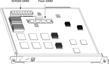
This section provides procedures to replace the SDRAM DIMM and Flash SIMM.
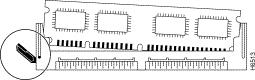
This section provides the steps for replacing the 64-MB SDRAM DIMM. The SDRAM resides on a single DIMM on the MSM (see Figure 7). The default SDRAM configuration is 64 MB. If you determine that a system problem is caused by the DIMM, a DIMM replacement might be required.
Follow these steps to remove the existing DIMM:
| Caution To prevent ESD damage, handle DIMMs by the card edges only. |
| Caution When removing or inserting the MSM, always wear an electrostatic discharge (ESD) wrist strap connected to the ESD wrist strap connector located beneath the Catalyst switch power supplies. |
Step 2 Use a screwdriver to loosen the two captive installation screws, and then remove the MSM using the ejector levers. Place the MSM on an antistatic mat.
Step 3 Locate the SDRAM DIMM (see Figure 7).
Step 4 Locate the release lever on the DIMM socket (see circle in Figure 8) and release the DIMM from the socket as shown.
Step 5 When one end of the DIMM is released from the socket, grasp the ends of the DIMM with your thumb and forefinger and pull the DIMM completely out of the socket. Handle the edges of the DIMM only. (See Figure 9.)
Step 6 Place the DIMM in an antistatic bag to protect it from ESD damage.
This completes the DIMM removal procedure. Proceed to the next section to install the new DIMM.
Follow these steps to install a new DIMM.
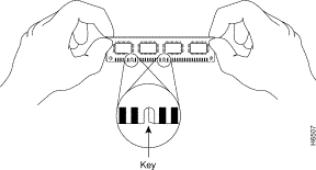
The SDRAM DIMM is a sensitive component that is susceptible to ESD damage. Handle the DIMM by the edges only; avoid touching the memory modules, pins, or traces (the metal fingers along the connector edge of the DIMM). (See Figure 9.)
| Caution To prevent ESD damage, handle the DIMM as shown in Figure 9. |
Use the following procedure to install a new SDRAM DIMM:
Step 2 Hold the DIMM between your thumbs and forefingers, component side up, with the connector edge (the metal fingers) down. (See Figure 9.)
Step 3 Tilt the DIMM to approximately the same angle as the socket and insert the connector edge into the socket. Note the two notches (keys) on the connector edge of the DIMM. (See Figure 9.) These keys are intended to assure correct orientation of the DIMM in the socket.
| Caution When inserting the DIMM, use firm but not excessive pressure. If you damage a socket, you will have to return the MSM to Cisco for repair. |
Step 4 Note the orientation of the socket key on the SDRAM DIMM and the DIMM socket. Gently push the DIMM into the socket until the release lever is flush against the side of the DIMM socket (see Figure 10) and the DIMM's edge connector is fully inserted. If necessary, rock the DIMM gently back and forth to seat it properly.
Step 5 When the DIMM is installed, check that the release lever is flush against the side of the DIMM socket. (See Figure 10.) If it is not, the DIMM might not be seated properly. If the DIMM appears misaligned, carefully remove it according to the removal procedure, and reseat it in the socket. Push the DIMM firmly back into the socket until the release lever is flush against the side of the DIMM socket.
Step 6 Guide the MSM back into the switch slot, aligning the sides of the MSM with the guides in the slot (avoid touching the components on the MSM). While keeping the MSM oriented horizontally, carefully slide it into the slot until its front panel contacts the ejector levers.
Step 7 Using the thumb and forefinger of each hand, simultaneously push the left lever and the right lever in to fully seat the MSM in the backplane connector.
Step 8 Use a screwdriver to tighten the captive installation screws on the left and right sides of the module.
Step 9 Check the status of the module as follows:
If the system fails to boot properly, or if the console terminal displays a checksum or memory error, check if the DIMM is installed correctly. If the DIMM appears to stick out or rest in the socket at an angle, remove the DIMM and reinsert it. Then replace the MSM and reboot the system for another installation check.
If after several attempts the system fails to restart properly, contact a service representative for assistance. Before you call, note any error messages, unusual LED states, or any other indications that might help solve the problem.
This completes the DIMM replacement procedure.
This section provides the steps for replacing the 8-MB Flash SIMM. The Flash resides on a single SIMM on the MSM. The default Flash SIMM configuration is 8 MB and is expandable to 16 MB. If you determine that a system problem is caused by the SIMM, a SIMM replacement might be required.
Follow these steps to remove the existing SIMM:
| Caution To prevent ESD damage, handle SIMMs by the card edges only. |
| Caution When removing or inserting the MSM, always wear an ESD wrist strap connected to the ESD wrist strap connector located beneath the Catalyst switch power supplies. |
Step 2 Use a screwdriver to loosen the two captive installation screws, and then remove the MSM using the ejector levers. Place the MSM on an antistatic mat.
Step 3 Locate the Flash SIMM (see Figure 7).
Step 4 Release the spring clips from the SIMM and release the SIMM from the socket (see Figure 11).
Step 5 When both ends of the SIMM are released from the socket, grasp the ends of the SIMM with your thumb and forefinger and pull the SIMM completely out of the socket. Handle the edges of the SIMM only; avoid touching the memory module or pins, and the metal traces, or fingers, along the socket edge.
Step 6 Place the SIMM in an antistatic bag to protect it from ESD damage.
This completes the SIMM removal procedure. Proceed to the next section to install the new SIMMs.
Follow these steps to install a new SIMM.
SIMMs are sensitive components that are susceptible to ESD damage. Handle SIMMs by the edges only; avoid touching the memory modules, pins, or traces (the metal fingers along the connector edge of the SIMM). (See Figure 12.)
Step 2 Hold the SIMM between your thumbs and forefingers, component side up, with the connector edge (the metal fingers) away from you.
Step 3 Tilt the SIMM to approximately the same angle as the socket and insert the connector edge into the socket.
Step 4 Gently push the SIMM into the socket until the spring clips snap over the ends of the SIMM. If necessary, rock the SIMM gently back and forth to seat it properly.
Step 5 When the SIMM is installed, check the alignment holes and ensure that the spring retainer is visible. If it is not, the SIMM is not seated properly. If the SIMM appears misaligned, carefully remove it and reseat it in the socket. Push the SIMM firmly back into the socket until the retainer springs snap into place.
Step 6 Guide the MSM back into the switch slot, aligning the sides of the MSM with the guides in the slot (avoid touching the components on the MSM). While keeping the MSM oriented horizontally, carefully slide it into the slot until its front panel contacts the ejector levers.
Step 7 Using the thumb and forefinger of each hand, simultaneously push the left lever and the right lever in to fully seat the MSM in the backplane connector.
Step 8 Use a screwdriver to tighten the captive installation screws on the left and right sides of the module.
Step 9 Check the status of the module as follows:
If the system fails to boot properly, or if the console terminal displays a checksum or memory error, check if the SIMM is installed correctly. If the SIMM appears to stick out or rest in the socket at an angle, remove the SIMM and reinsert it. Then replace the MSM and reboot the system for another installation check.
If after several attempts the system fails to restart properly, contact a service representative for assistance. Before you call, note any error messages, unusual LED states, or any other indications that might help solve the problem.
This completes the SIMM replacement procedure.
Catalyst 6000 and 6500 series modules, when installed in a system, comply with the standards listed in Table 17.
Table 17 Regulatory Standards Compliance
| 1EMC = Electromagnetic Compatibility.
2CE = European Compliance. 3UL = Underwriters Laboratory. 4CSA = Canadian Standards Association. 5EN = European Norm. 6IEC = International Electrotechnical Commission. 7TS = Technical Specification. 8AS/NZS = Standards Australia/Standards New Zealand. 9FCC = Federal Communications Commission. 10CFR = Code of Federal Regulations. 11ICES = International Commerce Exchange Systems. 12UTP = unshielded twisted-pair. 13VCCI = Voluntary Control Council for Information Technology Equipment. 14FTP = foil twisted-pair. |
For additional information on Catalyst 6000 and 6500 series switches and command-line interface (CLI) commands, see the Catalyst 6000 and 6500 Series Software Configuration Guide and the Catalyst 6000 and 6500 Series Command Reference publication.
For detailed hardware configuration and maintenance procedures, see the Catalyst 6000 and 6500 Series Installation Guide.
For additional information on Cisco IOS commands, see the Configuration Fundamentals Command Reference publication.
Cisco Connection Online (CCO) is Cisco Systems' primary, real-time support channel. Maintenance customers and partners can self-register on CCO to obtain additional information and services.
Available 24 hours a day, 7 days a week, CCO provides a wealth of standard and value-added services to Cisco's customers and business partners. CCO services include product information, product documentation, software updates, release notes, technical tips, the Bug Navigator, configuration notes, brochures, descriptions of service offerings, and download access to public and authorized files.
CCO serves a wide variety of users through two interfaces that are updated and enhanced simultaneously: a character-based version and a multimedia version that resides on the World Wide Web (WWW). The character-based CCO supports Zmodem, Kermit, Xmodem, FTP, and Internet e-mail, and it is excellent for quick access to information over lower bandwidths. The WWW version of CCO provides richly formatted documents with photographs, figures, graphics, and video, as well as hyperlinks to related information.
You can access CCO in the following ways:
For a copy of CCO's Frequently Asked Questions (FAQ), contact cco-help@cisco.com. For additional information, contact cco-team@cisco.com.
Note If you are a network administrator and need personal technical assistance with a Cisco product that is under warranty or covered by a maintenance contract, contact Cisco's Technical Assistance Center (TAC) at 800 553-2447, 408 526-7209, or tac@cisco.com. To obtain general information about Cisco Systems, Cisco products, or upgrades, contact 800 553-6387, 408 526-7208, or cs-rep@cisco.com
Cisco documentation and additional literature are available in a CD-ROM package, which ships with your product. The Documentation CD-ROM, a member of the Cisco Connection Family, is updated monthly. Therefore, it might be more up to date than printed documentation. To order additional copies of the Documentation CD-ROM, contact your local sales representative or call customer service. The CD-ROM package is available as a single package or as an annual subscription. You can also access Cisco documentation on the World Wide Web at http://www.cisco.com, http://www-china.cisco.com, or http://www-europe.cisco.com.
If you are reading Cisco product documentation on the World Wide Web, you can submit comments electronically. Click Feedback on the title bar, and then select Documentation. After you complete the form, click Submit to send it to Cisco. We appreciate your comments.
![]()
![]()
![]()
![]()
![]()
![]()
![]()
![]()
Posted: Fri Feb 7 06:51:18 PST 2003
All contents are Copyright © 1992--2002 Cisco Systems, Inc. All rights reserved.
Important Notices and Privacy Statement.