|
|

Table Of Contents
Cisco Catalyst 6500 Series Application-Oriented Networking Module Installation Note
Environmental and System Requirements
Preparing to Install the Module
Installing and Removing the Module
Cisco Product Security Overview
Reporting Security Problems in Cisco Products
Obtaining Technical Assistance
Cisco Technical Support & Documentation Website
Definitions of Service Request Severity
Obtaining Additional Publications and Information
Cisco Catalyst 6500 Series Application-Oriented Networking Module Installation Note
Product Number: WS-SVC-AON-1-K9
This publication describes how to install the Cisco Catalyst 6500 Series AON Module Services Module (AON-SM) for the Catalyst 6500 Series switches. The AON module provides the following:
•
Enhanced security and reliability that enables reliable message delivery and provides message-level security in addition to existing network-level security.
•
•
•
Contents
This publication contains these sections:
•
•
•
•
Safety Overview
Front Panel Description
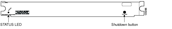
This section describes the physical attributes of the AON module.
Figure 1 shows the AON module front panel.
Figure 1 Application-Oriented Networking Module Front Panel
LEDs
When the AON module powers up, it initializes the various hardware components and communicates with the supervisor engine. The Status LED indicates the supervisor engine operations and the initialization results. During the normal initialization sequence, the status LED changes from off to red, orange, and green.
Note
Table 1 describes the Status LED operation.
Table 1 AON Module LEDs
Status
Off
•
•
•
–
–
Red
•
•
Orange
•
•
•
•
Green
•
Green to orange
•
1 Enter the show environment temperature mod command to display the temperature of each of the four sensors on the AON module.
2 CLI = command-line interface.
Environmental and System Requirements
This section describes the environmental and system requirements for the AON module:
Environmental Requirements
Table 2 lists the environmental requirements for the AON module.
System Requirements
Before you install the AON module in the Catalyst 6500 series switch, make sure that the switch meets these hardware and software requirements:
•
•
For more information, refer to the Catalyst 6500 Series Switch Installation Guide at http://www.Cisco.com/univercd/home/home.htm.
For the AON software installation and configuration instructions, refer to the AON Installation and Administration Guide.
Memory Requirements
The AON module memory is not configurable.
Hardware Supported
Before you can use the AON module, you must have a a Policy Feature Card (PFC), Supervisor Engine 720 with an MSFC3 or Supervisor Engine 2 with an MSFC2, and any module that has ports to connect to the server and client networks.
Power Supply
You can place the AON module in any slot in the Catalyst 6500 series chassis except for slot one. The AON module operates on power that is supplied by the chassis.
Software Requirements
The AON module is supported on Cisco IOS Release 12.2(17d)SXB7. The module is also supported on Cisco IOS Release 12.(18)SXE1 with the Catalyst operating system software release 8.4(2a).
See the AON release note for software requirements.
Installing the Module
These sections describe how to install the AON module:
•
•
Preparing to Install the Module
Before installing the AON module, make sure that the following items are available:
•
•
Required Tools
These tools are required to install the AON module in the Catalyst 6500 series switches:
•
•
•
Whenever you handle the AON module, always use a wrist strap or other grounding device to prevent electrostatic discharge (ESD).
Installing and Removing the Module
Caution
All Catalyst 6500 series switches support hot swapping, which allows you to install, remove, replace, and rearrange the modules without turning off the system power. For more information on removing the AON module from a switch, see the "Removing the Module" section.
When the switch detects that a module has been installed or removed, the system automatically runs diagnostic and discovery routines, acknowledges the presence or absence of the module, and resumes system operation.
These sections describe how to install and verify the operation of the AON module in the Catalyst 6500 series switches:
Slot Assignments
The Catalyst 6513 switch chassis has 13 slots.
•
•
•
•
Removing the Module
This section describes how to remove an existing module from a Catalyst 6500 series switch chassis.
Caution
Warning
To remove a module from the chassis, perform these steps:
Note
Step 1
This step assures that the space that is created by the removed module is maintained.
Note
Step 2
Step 3
Horizontal slots
a.
b.
Vertical slots
a.
b.
Step 4
Step 5
Warning
Installing a Module
This section describes how to install a module in the Catalyst 6500 series switch.
Caution
Caution
Warning
To install a module in the chassis, perform these steps:
Step 1
Step 2
Step 3
This action ensures that the EMI gaskets on all modules are fully compressed to maximize the opening space for the replacement module.
Note
Step 4
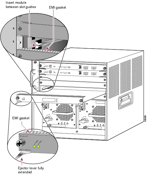
Step 5
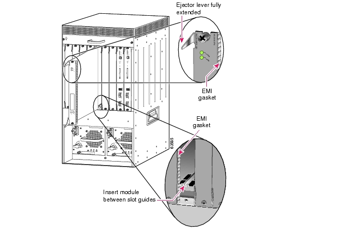
Figure 2 Positioning the Module in a Horizontal Slot Chassis
Step 6
Horizontal slots
a.
b.
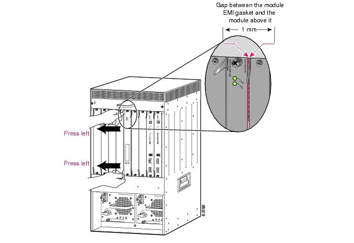
Figure 3 Clearing the EMI Gasket in a Horizontal Slot Chassis
c.
Caution
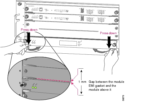
d.
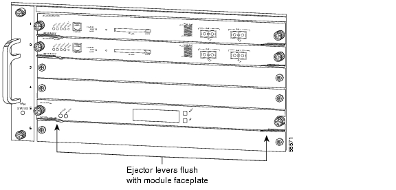
Figure 4 Ejector Lever Closure in a Horizontal Slot Chassis
Note
e.
Note
Vertical slots
a.
Figure 5 Positioning the Module in a Vertical Slot Chassis
b.
c.
Figure 6 Clearing the EMI Gasket in a Vertical Slot Chassis
Caution
d.
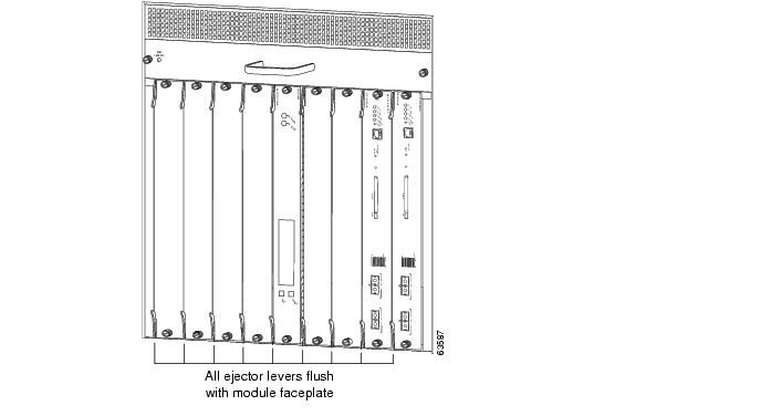
Figure 7 Ejector Lever Closure in a Vertical Slot Chassis
e.
Note
Verifying the Installation
When you install the module into the Catalyst 6500 series switch, the module goes through a startup sequence that requires no intervention. At the successful conclusion of the startup sequence, the green Status LED will light and remain on. If the Status LED does not show green, or if it shows a different color, refer to Table 1 to determine the modules status.
For software installation and configuration instructions, refer to the AON Installation and Administration Guide.
Using the CLI
The software interface for the module is the Cisco IOS and the Catalyst operating system command-line interface accessed through a Telnet connection to the switch or through the switch console interface. Refer to the Catalyst 6500 Series Switch Cisco IOS Software Configuration Guide and the Catalyst 6500 Series Switch Software Configuration Guide for details.
To understand the Cisco IOS command-line interface and Cisco IOS command modes, refer to Chapter 2, "Command-Line Interfaces," in the Catalyst 6500 Series Switch Cisco IOS Software Configuration Guide.
To understand the Catalyst operating system command-line interface and Catalyst operating system command modes, refer to Chapter 2, "Command-Line Interfaces," in the Catalyst 6500 Series Switch Configuration Guide.
You configure the module using the session command.
You can session into the module from the switch console and configure the module. The session is a Telnet interface through the Ethernet out-of-band channel (EOBC) of the switch backplane.
Related Documentation
For more detailed installation and configuration information for the AON module, refer to the following publications:
•
•
•
•
Translated Safety Warnings
Obtaining Documentation
Cisco documentation and additional literature are available on Cisco.com. Cisco also provides several ways to obtain technical assistance and other technical resources. These sections explain how to obtain technical information from Cisco Systems.
Cisco.com
You can access the most current Cisco documentation at this URL:
http://www.cisco.com/techsupport
You can access the Cisco website at this URL:
You can access international Cisco websites at this URL:
http://www.cisco.com/public/countries_languages.shtml
Product Documentation DVD
Cisco documentation and additional literature are available in the Product Documentation DVD package, which may have shipped with your product. The Product Documentation DVD is updated regularly and may be more current than printed documentation.
The Product Documentation DVD is a comprehensive library of technical product documentation on portable media. The DVD enables you to access multiple versions of hardware and software installation, configuration, and command guides for Cisco products and to view technical documentation in HTML. With the DVD, you have access to the same documentation that is found on the Cisco website without being connected to the Internet. Certain products also have .pdf versions of the documentation available.
The Product Documentation DVD is available as a single unit or as a subscription. Registered Cisco.com users (Cisco direct customers) can order a Product Documentation DVD (product number DOC-DOCDVD=) from the Ordering tool or Cisco Marketplace.
Cisco Ordering tool:
http://www.cisco.com/en/US/partner/ordering/
Cisco Marketplace:
http://www.cisco.com/go/marketplace/
Ordering Documentation
Beginning June 30, 2005, registered Cisco.com users may order Cisco documentation at the Product Documentation Store in the Cisco Marketplace at this URL:
http://www.cisco.com/go/marketplace/
Cisco will continue to support documentation orders using the Ordering tool:
•
http://www.cisco.com/en/US/partner/ordering/
•
http://www.cisco.com/univercd/cc/td/doc/es_inpck/pdi.htm
•
Documentation Feedback
You can rate and provide feedback about Cisco technical documents by completing the online feedback form that appears with the technical documents on Cisco.com.
You can send comments about Cisco documentation to bug-doc@cisco.com.
You can submit comments by using the response card (if present) behind the front cover of your document or by writing to the following address:
Cisco Systems
Attn: Customer Document Ordering
170 West Tasman Drive
San Jose, CA 95134-9883We appreciate your comments.
Cisco Product Security Overview
Cisco provides a free online Security Vulnerability Policy portal at this URL:
http://www.cisco.com/en/US/products/products_security_vulnerability_policy.html
From this site, you can perform these tasks:
•
•
•
A current list of security advisories and notices for Cisco products is available at this URL:
If you prefer to see advisories and notices as they are updated in real time, you can access a Product Security Incident Response Team Really Simple Syndication (PSIRT RSS) feed from this URL:
http://www.cisco.com/en/US/products/products_psirt_rss_feed.html
Reporting Security Problems in Cisco Products
Cisco is committed to delivering secure products. We test our products internally before we release them, and we strive to correct all vulnerabilities quickly. If you think that you might have identified a vulnerability in a Cisco product, contact PSIRT:
•
An emergency is either a condition in which a system is under active attack or a condition for which a severe and urgent security vulnerability should be reported. All other conditions are considered nonemergencies.
•
In an emergency, you can also reach PSIRT by telephone:
•
•
Tip
Never use a revoked or an expired encryption key. The correct public key to use in your correspondence with PSIRT is the one linked in the Contact Summary section of the Security Vulnerability Policy page at this URL:
http://www.cisco.com/en/US/products/products_security_vulnerability_policy.htm
The link on this page has the current PGP key ID in use.
Obtaining Technical Assistance
Cisco Technical Support provides 24-hour-a-day award-winning technical assistance. The Cisco Technical Support & Documentation website on Cisco.com features extensive online support resources. In addition, if you have a valid Cisco service contract, Cisco Technical Assistance Center (TAC) engineers provide telephone support. If you do not have a valid Cisco service contract, contact your reseller.
Cisco Technical Support & Documentation Website
The Cisco Technical Support & Documentation website provides online documents and tools for troubleshooting and resolving technical issues with Cisco products and technologies. The website is available 24 hours a day, at this URL:
http://www.cisco.com/techsupport
Access to all tools on the Cisco Technical Support & Documentation website requires a Cisco.com user ID and password. If you have a valid service contract but do not have a user ID or password, you can register at this URL:
http://tools.cisco.com/RPF/register/register.do
Note
Submitting a Service Request
Using the online TAC Service Request Tool is the fastest way to open S3 and S4 service requests. (S3 and S4 service requests are those in which your network is minimally impaired or for which you require product information.) After you describe your situation, the TAC Service Request Tool provides recommended solutions. If your issue is not resolved using the recommended resources, your service request is assigned to a Cisco engineer. The TAC Service Request Tool is located at this URL:
http://www.cisco.com/techsupport/servicerequest
For S1 or S2 service requests or if you do not have Internet access, contact the Cisco TAC by telephone. (S1 or S2 service requests are those in which your production network is down or severely degraded.) Cisco engineers are assigned immediately to S1 and S2 service requests to help keep your business operations running smoothly.
To open a service request by telephone, use one of the following numbers:
Asia-Pacific: +61 2 8446 7411 (Australia: 1 800 805 227)
EMEA: +32 2 704 55 55
USA: 1 800 553-2447For a complete list of Cisco TAC contacts, go to this URL:
http://www.cisco.com/techsupport/contacts
Definitions of Service Request Severity
To ensure that all service requests are reported in a standard format, Cisco has established severity definitions.
Severity 1 (S1)—Your network is "down," or there is a critical impact to your business operations. You and Cisco will commit all necessary resources around the clock to resolve the situation.
Severity 2 (S2)—Operation of an existing network is severely degraded, or significant aspects of your business operation are negatively affected by inadequate performance of Cisco products. You and Cisco will commit full-time resources during normal business hours to resolve the situation.
Severity 3 (S3)—Operational performance of your network is impaired, but most business operations remain functional. You and Cisco will commit resources during normal business hours to restore service to satisfactory levels.
Severity 4 (S4)—You require information or assistance with Cisco product capabilities, installation, or configuration. There is little or no effect on your business operations.
Obtaining Additional Publications and Information
Information about Cisco products, technologies, and network solutions is available from various online and printed sources.
•
http://www.cisco.com/go/marketplace/
•
•
•
http://www.cisco.com/go/iqmagazine
or view the digital edition at this URL:
http://ciscoiq.texterity.com/ciscoiq/sample/
•
•
http://www.cisco.com/en/US/products/index.html
•
http://www.cisco.com/discuss/networking
•
http://www.cisco.com/en/US/learning/index.html
This document is to be used in conjunction with the documents listed in the "Related Documentation" section.
Copyright © 2005 Cisco Systems, Inc. All rights reserved.
![]()
![]()
![]()
![]()
![]()
![]()
![]()
![]()
Posted: Wed Jun 21 08:53:04 PDT 2006
All contents are Copyright © 1992--2006 Cisco Systems, Inc. All rights reserved.
Important Notices and Privacy Statement.