|
|

Table Of Contents
Cisco Persistent Storage Device Module Installation and Configuration Note
Understanding How the PSD Works
Configuring and Managing the PSD
PSD Features in Release 1.1(1)
PSD Features in Release 1.0(1)
Installing and Removing the PSD
Configuring the Supervisor for the PSD
Saving and Restoring Configurations
Additional PSD Software Commands
Standards Compliance Specifications
Obtaining Technical Assistance
Cisco Persistent Storage Device Module Installation and Configuration Note
WS-SVC-PSD-1
This publication describes how to install and configure the Cisco Persistent Storage Device (PSD) on the Catalyst 6500 series switch. See the "Related Documentation" section for more information about software configuration for the switch.
Note
For translations of the warnings in this publication, see the "Safety Overview" section and refer to the Regulatory Compliance and Safety Information for the Catalyst 6500 series switches.
Contents
This publication consists of these sections:
•
•
•
•
Overview
This section describes the Catalyst 6500 and 7600 series PSD, how it operates, and how to manage it, and includes these sections:
•
•
Understanding How the PSD Works
The Cisco Persistent Storage Device (PSD) provides persistent storage capabilities to Cisco clients, and allows the clients to store data on the PSD's internal hard drive. Release 1.x provides content data records (CDR) backup capabilities for Cisco's Content Services Gateway (CSG). Release 2.0 adds CDR backup capabilities for the Cisco Gateway GPRS Serving Node (GGSN).
A single PSD can support both CSGs and GGSNs. The number of CSGs and GGSNs that can be supported by a single PSD is limited by the traffic load generated by each, as well as the duration of storage that you desire.
Storage and Retrieval on the PSD
Under normal conditions, a Cisco client will send content data records to Mediation Partners' servers. If those servers become unreachable—for any reason—records are then sent to the PSD for safekeeping until contact is re-established with the Charging Gateway (CG). Once contact is re-established, the client retrieves the records from the PSD, and forwards them to the CG.
Storage
Under normal conditions, the PSD provides backup capabilities when necessary—for example, during network outages. The PSD stores the payload from the packet in a queue, and is unaware of the content or format of that data, so that the data can be retrieved exactly as it was sent.
Retrieval
Once the client has determined that it's regular data server is reachable, you issue a CLI command to request that the data files for a given data store be transferred using FTP to a specified URL. You can also restore the configuration to a previously saved version that includes all the IP and application related configuration files. And, you can issue another CLI command to delete transferred files.
Note
Datastores
Datastores are locations for a particular client that map to the PSD's hard drive. In this release, you can create up to twenty (20) separate datastores and name them. Twenty datatstores support four MWAM cards in a single chassis with each running five client images, and allows each client to have its own data store. Additionally, datastores have access lists that you can configure to allow specific clients to read and write to specific datastores. Currently, the number of accessors is limited to two (2). The data store access list contains an optional port number in addition to the IP address for each accessor.
When the preferred destination for data becomes unavailable, or during any network outage, data is sent to the PSD and is stored on a "first come, first served" basis. The maximum record storage capability of the PSD is 37 gigabytes, and is allocated as needed.
Format of Datastore Data Files
A data store is comprised of one or more data files. Each data file is composed of multiple records that are constructed of various management related fields, data, and an end-of-record (EOR) indicator. If you need to retrieve data files using FTP (files that are usually corrupt), you will need to understand the format of the data. The following is the format for each record written to a data file:
•
–
–
–
•
•
•
•
An End-of-File (EOF) marker follows the last record in a file. This marker is a 4 byte field with a value of 0xFFFFFFFF.
Data files are named with a numeric prefix and a file extension of ".data" (for example, 000000001.data).
Platform and Network Planning
In release 1.x and above, the PSD is implemented as a single linecard that sits in a Catalyst 6500 or 7600 chassis.
The PSD hardware supports the following features:
•
•
•
The typical configuration will be a chassis with up to twenty active co-resident clients and a single PSD serving those clients. The number of PSDs required is determined based on expected network traffic, and the corresponding records that Cisco clients would generate (for example, billing records from a CSG).
Cisco recommends that you consult your sales engineer for specific network planning. You can, however, get a general idea of how many PSDs your network requires by using the following criteria.
To determine the number of PSDs you need, take the maximum value of the following variables:
•
•
•
Additionally, the following values will be useful to you for network planning:
•
•
•
•
Configuring and Managing the PSD
The PSD is configured and managed by sessioning to the PSD module from IOS on the Supervisor card, or with Telnet when Telnet is enabled. The PSD is then configured using a CLI much like IOS. In addition to a number of administrative and troubleshooting commands on the PSD, there are basic configuration commands that allow you to create and manage datastores on the PSD, and to assign clients that may access (read/write) those datastores. Typically, you would configure a datastore for each client, or pair of redundant clients.
Additionally, you must configure the clients to inform them of the location and presence of a PSD.
New Features in Release 2.0
The following features are new for the PSD Release 2.0:
•
•
•
•
•
•
PSD Features in Release 1.1(1)
These are the features for the Cisco PSD software release 1.1(1)
•
PSD Features in Release 1.0(1)
These are the features for the PSD in software release 1.0(1):
•
•
•
Supported Platforms
•
•
Finding Support Information for Platforms and Cisco IOS Software Images
Use Cisco Feature Navigator to find information about platform support and Cisco IOS software image support. Access Cisco Feature Navigator at http://www.cisco.com/go/fn. You must have an account on Cisco.com. If you do not have an account or have forgotten your username or password, click Cancel at the login dialog box and follow the instructions that appear.
Supported MIBs, and RFCs
The following sections provide information about the MIBs and RFCs that are supported on the PSD:
MIBs
•
•
•
RFCs
•
•
•
Front Panel Description
The PSD front panel (see Figure 1) includes a STATUS LED and SHUTDOWN button.
Figure 1 Persistent Storage Device Module
STATUS LED
The STATUS LED indicates the operating states of the PSD. Table 1 describes the LED operation.
SHUTDOWN Button
Caution
To avoid corrupting the PSD hard disk, you must correctly shut down the PSD before you remove it from the chassis or disconnect the power. This shutdown procedure is normally initiated by commands entered at the Supervisor engine CLI prompt or the PSD CLI prompt.
If the PSD fails to respond to these commands properly, you can use the SHUTDOWN button on the front panel to initiate the shutdown procedure.
The shutdown procedure may require several minutes. The STATUS LED turns orange when the PSD shuts down.
Specifications
Table 2 describes the specifications for the PSD.
Safety Overview
Safety warnings appear throughout this document in procedures that may harm you if performed incorrectly.
For additional safety information, refer to documents listed in the "Related Documentation" section.
Warning
Warning
Warning
Warning
Warning
Warning
Warning
Warning
Warning
Warning
Warning
Software Requirements
Table 3 lists the PSD software versions supported by Cisco IOS software.
Hardware Requirements
Table 4 lists the PSD hardware versions supported by Cisco IOS software.
Table 4 PSD Supported Hardware Version
Supervisor Engine 2 with an MSFC2 or Supervisor 720 with an MSFC3
Required Tools
Note
These tools are required to install the PSD in the Catalyst 6500 series switch:
•
•
•
•
Whenever you handle the PSD, always use a wrist strap or other grounding device to prevent electrostatic discharge (ESD).
Installing and Removing the PSD
Warning
All the Catalyst 6500 series family switches support hot swapping, which allows you to install, remove, replace, and rearrange modules without turning off the system power. For more information on removing the PSD from a switch, see the "Removing a Module" section.
Caution
When the system detects that a module has been installed or removed, the system automatically runs diagnostic and discovery routines, acknowledges the presence or absence of the module, and resumes system operation.
To install and use the PSD, you need to complete the following actions:
•
•
•
This section describes how to install and verify the operation of the PSD in the Catalyst 6500 family switch, and contains the following sections:
Slot Assignments
The Catalyst 6509 switch chassis has nine slots. The module can occupy any slot in the Catalyst 6500 series chassis.
Note
•
•
•
•
Removing a Module
This section describes how to remove an existing module from a chassis slot.
Warning
Warning
Warning
To remove a Supervisor engine or module from the chassis, perform these steps:
Step 1
Note
Step 2
This action ensures that the space created by the removed module is maintained.
Note
Step 3
Step 4
Horizontal slots
a.
b.
Vertical slots
a.
b.
Step 5
Step 6
Warning
Installing a Module
This section describes how to install modules in the Catalyst 6500 series and Catalyst 6000 family switches.
Caution
Warning
Warning
Warning
To install a Supervisor engine or module in the chassis, perform these steps:
Step 1
Step 2
Step 3
This action ensures that the EMI gaskets on all modules are fully compressed in order to maximize the opening space for the new module or the replacement module.
Note
Step 4
To remove a module, refer to "Removing a Module" section.
Step 5
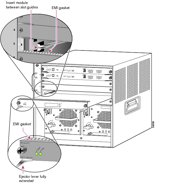
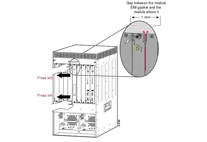
Figure 2 Positioning the Module in a Horizontal Slot Chassis
Step 6
Horizontal slots
a.
b.
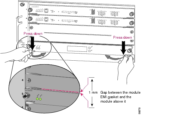
Figure 3 Clearing the EMI Gasket in a Horizontal Slot Chassis
c.
Caution
d.
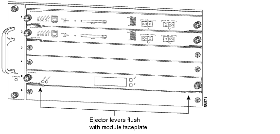
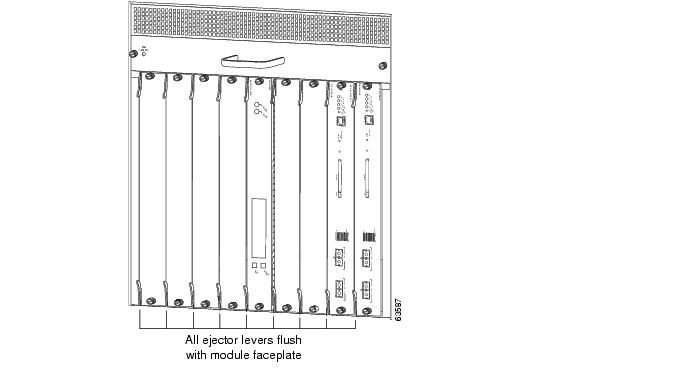
Figure 4 Ejector Lever Closure in a Horizontal Slot Chassis
Note
e.
Note
Vertical slots
a.
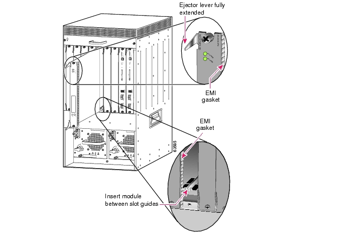
Figure 5 Positioning the Module in a Vertical Slot Chassis
b.
c.
Figure 6 Clearing the EMI Gasket in a Vertical Slot Chassis
Caution
d.
Figure 7 Ejector Lever Closure in a Vertical Slot Chassis
e.
Note
Note
Verifying the Installation
This section describes how to verify the PSD installation.
Cisco IOS Software
To verify that the system acknowledges the new module and has brought it online, enter the show module [mod-num | all ] command.
This example shows the output of the show module command:
Router#show moduleMod Ports Card Type Model Serial No.--- ----- -------------------------------------- ------------------ -----------1 2 Catalyst 6000 supervisor 2 (Active) WS-X6K-SUP2-2GE SAL06396QLA2 2 Catalyst 6000 supervisor 2 (Standby) WS-X6K-SUP2-2GE SAL061800UB3 48 48 port 10/100 mb RJ45 WS-X6348-RJ-45 SAL06200V6W4 3 Network Analysis Module WS-SVC-NAM-1 SAD064403UB5 3 Persistent Storage Device WS-SVC-PSD-1 SAD060301SU6 3 Persistent Storage Device WS-SVC-PSD-1 SAD060301SVMod MAC addresses Hw Fw Sw Status--- ---------------------------------- ------ ------------ ------------ -------1 0006.d65b.e1bc to 0006.d65b.e1bd 3.10 6.1(3) 7.5(0.94) Ok2 0005.7485.bde8 to 0005.7485.bde9 3.7 6.1(3) 7.5(0.94) Ok3 0009.1243.23cc to 0009.1243.23fb 6.1 5.4(2) 7.5(0.94) Ok4 0002.7ee4.b046 to 0002.7ee4.b04d 1.0 7.2(1) 2.2(1a) Ok5 00e0.b0ff.3630 to 00e0.b0ff.3637 0.101 7.5(0.61) 1.0(1) Ok6 00e0.b0ff.3530 to 00e0.b0ff.3537 0.101 7.5(0.61) 1.0(1) OkMod Sub-Module Model Serial Hw Status--- --------------------------- --------------- --------------- ------- -------1 Policy Feature Card 2 WS-F6K-PFC2 SAL06396LVK 3.3 Ok1 Cat6k MSFC 2 daughterboard WS-F6K-MSFC2 SAL06365RJM 2.5 Ok2 Policy Feature Card 2 WS-F6K-PFC2 SAL061735WF 3.2 Ok2 Cat6k MSFC 2 daughterboard WS-F6K-MSFC2 SAL06131NAL 2.3 OkMod Online Diag Status--- -------------------1 Pass2 Pass3 Pass4 Pass5 Pass6 PassWhen the PSD initially boots, by default it runs a partial memory test. To perform a full memory test, enter the hw-module module module_number reset device:partition mem-test-full command.
A full memory test takes more time to complete than a partial memory test depending on the memory size. Table 5 lists the memory test time and approximate boot time for a partial memory test.
You also can use the hw-module module module_number mem-test-full command in a Cisco IOS system. This example shows how to do a full memory test for module 4:
Router(config)# hw-module module 4 mem-test-full
Note
router# configure terminal diag level completeConfiguring the PSD
See the following sections for configuration tasks for the PSD. Each task in the list is identified as either required or optional.
•
•
•
•
•
There are several external interfaces that are available to configure and manage the PSD. They include the following:
MP (Maintenance Partition) Command Line Interface.
When you boot the MP image (from compact flash), and login to the card, you are presented with a command line interface that allows you to perform activities such as administration tasks, configuration, troubleshooting, and to upgrade the application image.
AP (Application Partition) Command Line Interface.
When you boot the AP image from the hard disk, and login to the card, you are presented with a command line interface that is similar to IOS. The AP commands allow you to configure the PSD, and to display the status of the PSD.
There is a specific subset of the PSD CLI commands for the following tasks:
•
•
•
•
•
•
•
IOS Supervisor Command Line Interface.
This is the command line provided by the IOS image on the Supervisor card. There are IOS commands that allow you to interact with the PSD card. The Supervisor CLI also provides commands by which the CSG or GGSN is configured to communicate with the PSD card.
SNMP interfaces. The SNMP agent on the PSD can be configured and activated. When activated, you can then define a read community string. A network agent with connectivity to the PSD, and knowledge of the SNMP read community string, may issue SNMP get/walk type requests to manage and monitor the PSD.
Configuring the Supervisor for the PSD
Adding the PSD to the Corresponding VLAN
By default, the PSD is in trunking mode with native VLAN 1.
Note
Initial PSD Configuration
Before you can use the PSD for data storage, you must log into the PSD root account and configure the following:
•
•
•
•
•
•
•
•
•
•
–
–
–
To configure these required parameters for the PSD, follow these steps:
Step 1
Router# show module modStep 2
Router# session slot module_number processor 1Step 3
Step 4
Note
Step 5
root@localhost# ip address ip-address subnet-maskStep 6
root@localhost# ip broadcast broadcast-addressStep 7
root@localhost# ip host [host-name]Step 8
root@localhost# ip gateway default-gateway
Note
Step 9
root@localhost# ip domain domain-nameStep 10
root@localhost# ip nameserver ip-address [ip-address2] [ip-address-3]
Note
Step 11
root@localhost# show ipStep 12
root@localhost# datastore create ciscoroot@localhost# datastore access enable cisco 1.2.3.4 port numberroot@localhost# show datastore all or ciscoStep 13
root@localhost# in-service
Note
Step 14
root@localhost# snmp-agent location-string
Note
Step 15
root@localhost# snmp-contact contact-stringStep 16
root@localhost# snmp-name name-string
Note
Step 17
root@localhost# snmp-community community-string
Note
Step 18
root@localhost# show snmpStep 19
root@localhost# telnet-server enableAfter completing this configuration, the PSD is ready to use with other Cisco clients.
This example shows how to configure the PSD:
Router# session slot 8 processor 1The default escape character is Ctrl-^, then x.You can also type 'exit' at the remote prompt to end the sessionTrying 127.0.0.81 ... OpenCisco Persistent Storage (WS-SVC-PSD-1)login: rootPassword:Cisco Persistent Storage Device (WS-SVC-PSD-1) Console, 1.0(1)Copyright (C) 2002-2003 by cisco Systems, Inc.WARNING! Default password has not been changed!root@localhost.localdomain# ip address 192.18.12.221 255.255.255.192root@localhost.localdomain# ip host psd1root@psd1.localdomain# ip gateway 192.18.12.193root@psd1.localdomain# ip domain cisco.comroot@psd1.cisco.com# ip nameserver 161.44.11.21root@psd1.cisco.com# show ipIP address: 192.18.12.221Subnet mask: 255.255.255.192IP Broadcast: 192.18.255.255DNS Name: psd1.cisco.comDefault Gateway: 192.18.12.193Nameserver(s): 161.44.11.21FTP Server: disabledTelnet Server: disabledroot@psd1.cisco.com# snmp-agent enableroot@psd1.cisco.com# snmp-agent community readroot@psd1.cisco.com# snmp-agent location "Cisco Lab, Building 10 Lab 4"root@psd1.cisco.com# snmp contact "Lab Admin, 555-1212"root@psd1.cisco.com# show snmp-agentSNMP Agent: psd1.cisco.comstatus: enabledip address: 172.18.12.221community string: readSNMPv1: supportedSNMPv2c: supportedSNMPv3: not-supportedsysDescr: Linux psd1.cisco.com 2.4.18 #1 SMP Wed Jul 16 11:18:19 EDT 2003 i686sysObjectID: OID: enterprises.ucdavis.ucdSnmpAgent.linuxsysContact: Lab Admin, 555-1212sysName: not-configuredsysLocation: Cisco Lab, Building 10 Lab 4root@psd1.cisco.com#
Caution
Step 1
router# session slot slot_num processor processorStep 2
Note
root@localhost.localdomain# show ip
root@localhost.localdomain# show snmp-agent
root@localhost.localdomain# show datastore all .
Save this file in a secure location for backup purposes.
Note
Transfering and Purging Data Files and Datastores
The PSD allows you transfer and purge whole datastores, as well as individual files that exist in a datastore. See Troubleshooting the PSD for more information about how to identify corrupt data files.
To transfer and purge datastores and datastore files, perform the following procedure:
Step 1
	datastore transfer {keep | delete} {data-files | salvage-files | all} data-store-name
    ftp-url
The specified URL has the following format: ftp://username:password@hostname/fully-qualified-destination-directory
Step 2
datastore purge transferred {data-files | salvage-files | all} data-store-name
Administering the PSD
This section contains the various administrative tasks you can perform on the PSD with Cisco IOS:
•
Logging in to the PSD
Note
Table 6 shows the user levels and passwords for the PSD's Application Partition.
Table 6 PSD Users and Passwords for the AP
User
Password
root
cisco
Table 7 shows the user levels and passwords for the PSD's Application Partition.
Table 7 PSD Users and Passwords for the MP
User
Password
root
cisco
guest
cisco
Note
When you boot into either the application image or the maintenance image and set up IP information, that information is synched between the images. However, if you change passwords, that information is not synched between the images, and is not reflected on the unchanged image.
To allow remote Telnet sessions, use the telnet-server enable command.
To log in to the PSD, follow these steps:
Step 1
Step 2
Router# session slot 8 processor 1The default escape character is Ctrl-^, then x.You can also type 'exit' at the remote prompt to end the sessionTrying 127.0.0.81 ... OpenPersistent Storage Module (WS-SVC-PSD-1)Step 3
login: rootStep 4
Password:After a successful login, the command line prompt appears as follows:
Persistent Storage Module (WS-SVC-PSD-1) Console, 1.0(1)Copyright (c) 1999-2002 by cisco Systems, Inc.WARNING! Default password has not been changed!root@localhost#Changing the PSD CLI Passwords
If you have not changed the password from the factory-set default, a warning message displays when you log in to the PSD.
Note
Note
To change the password, follow these steps while you are logged in to the root account on the PSD:
Step 1
root@localhost# password usernameTo change the root password, make a Telnet connection to the PSD and use the password root command.
To change the guest password in MP mode only, make a Telnet connection to the PSD and use the password guest command.
Step 2
Changing password for user rootNew UNIX password:Step 3
Retype new UNIX password:passwd: all authentication tokens updated successfullyThis example shows how to set the password for the root account:
root@localhost# password rootChanging password for user rootNew UNIX password:Retype new UNIX password:passwd: all authentication tokens updated successfullyIf you forget or lose the password, you can enter the clear module pc-module module number password command from the IOS Supervisor CLI to restore the password for the root account to "cisco".
Resetting the PSD
If you cannot reach the PSD through the CLI or an external Telnet session, enter the hardware_module module module_number reset command to reset and reboot the PSD. The reset process requires several minutes.
When the PSD initially boots, by default it runs a partial memory test. To perform a full memory test, use the mem-test-full keyword in the hw-module module module_number reset device:partition mem-test-full command.
When you next reset the PSD, the full memory test runs. A full memory test takes more time to complete than a partial memory test. See Table 5 for memory test times.
You can also use the hw-module module module_number mem-test-full configuration to run a memory test. This example shows a full memory test for module 5:
Router(config)# hw-module slot 5 memory test fullTo reset the module from the CLI, perform this task in privileged mode:
This example shows how to reset the PSD that is installed in slot 9 from the CLI:
Router# hardware_module mod 9 reset cf:1 memtest-fullProceed with reload of module? [confirm] y% reset issued for module 9
Note
Upgrading the PSD Software
You can upgrade both the application software and the maintenance software. To upgrade the application software, see the "Upgrading the PSD Application Software" section. To upgrade the maintenance software, see the "Upgrading the PSD Maintenance Software" section.
Caution
Note
Upgrading the PSD Maintenance Software
Note
To upgrade the PSD maintenance software, follow these steps:
Step 1
Step 2
Step 3
Router# hardware_module module 9 resetDevice BOOT variable for reset = hdd:1Warning:Device list is not verified.Proceed with reload of module? [confirm]% reset issued for module 9Router#00:31:11:%SNMP-5-MODULETRAP:Module 9 [Down] Trap00:31:11:SP:The PC in slot 9 is shutting down. Please wait ...00:31:25:SP:PC shutdown completed for module 900:31:25:%C6KPWR-SP-4-DISABLED:power to module in slot 9 set off (adminrequest)00:31:28:SP:Resetting module 9 ...00:31:28:%C6KPWR-SP-4-ENABLED:power to module in slot 9 set on00:33:26:%SNMP-5-MODULETRAP:Module 9 [Up] Trap00:33:26:%DIAG-SP-6-BYPASS:Module 9:Online Diagnostics is Bypassed00:33:26:%OIR-SP-6-INSCARD:Card inserted in slot 9, interfaces are nowonlineStep 4
Step 5
root@localhost# upgrade ftp-urlftp-url is the FTP location and name of the PSD software image file.
Note
Step 6
Step 7
Step 8
Router# hardware_module module 9 reset cf:1Device BOOT variable for reset = cf:1Warning:Device list is not verified.Proceed with reload of module? [confirm]% reset issued for module 9Router#00:16:06:%SNMP-5-MODULETRAP:Module 9 [Down] Trap00:16:06:SP:The PC in slot 9 is shutting down. Please wait ...00:16:21:SP:PC shutdown completed for module 900:16:21:%C6KPWR-SP-4-DISABLED:power to module in slot 9 set off (adminrequest)00:16:24:SP:Resetting module 9 ...00:16:24:%C6KPWR-SP-4-ENABLED:power to module in slot 9 set on00:18:21:%SNMP-5-MODULETRAP:Module 9 [Up] Trap00:18:21:%DIAG-SP-6-BYPASS:Module 9:Online Diagnostics is Bypassed00:18:21:%OIR-SP-6-INSCARD:Card inserted in slot 9, interfaces are nowonlineRouter#Step 9
root@localhost# show ipStep 10
a.
b.
c.
d.
e.
f.
g.
h.
Step 11
Router# hardware_module module 9 resetThis example shows how to upgrade the PSD maintenance software:
Router#Router# hardware_module module 9 resetDevice BOOT variable for reset = hdd:1Warning:Device list is not verified.Proceed with reload of module? [confirm]% reset issued for module 9Router#00:31:11:%SNMP-5-MODULETRAP:Module 9 [Down] Trap00:31:11:SP:The PC in slot 9 is shutting down. Please wait ...00:31:25:SP:PC shutdown completed for module 900:31:25:%C6KPWR-SP-4-DISABLED:power to module in slot 9 set off (adminrequest)00:31:28:SP:Resetting module 9 ...00:31:28:%C6KPWR-SP-4-ENABLED:power to module in slot 9 set on00:33:26:%SNMP-5-MODULETRAP:Module 9 [Up] Trap00:33:26:%DIAG-SP-6-BYPASS:Module 9:Online Diagnostics is Bypassed00:33:26:%OIR-SP-6-INSCARD:Card inserted in slot 9, interfaces are nowonlineRouter#Router# session slot 9 proc 1The default escape character is Ctrl-^, then x.You can also type 'exit' at the remote prompt to end the sessionTrying 127.0.0.91 ... OpenPersistent Storage Module (WS-SVC-PSD-1)login:rootPassword:Cisco Persistent Storage Module (WS-SVC-PSD-1) Console, 2.2(0.1)Copyright (c) 1999-2002 by cisco Systems, Inc.WARNING! Default password has not been changed!root@localhost.cisco.com#root@localhost.cisco.com# upgrade ftp://host/pub/rmon/mp.1-1-0-1.bin.gzuser password:Downloading image...ftp://host/pub/rmon/mp.1-1-0-1.bin.gz (11065K)- [########################] 11065K | 837.65K/s11331153 bytes transferred in 13.21 sec (837.64k/sec)Uncompressing the image...Verifying the image...Applying the Maintenance image.This may take several minutes...Upgrade of Maintenance image completed successfully.root@hostname.cisco.com# exitRouter# hardware_module module 9 reset cf:1Device BOOT variable for reset = cf:1Warning:Device list is not verified.Proceed with reload of module? [confirm]% reset issued for module 9Router#02:27:19:%SNMP-5-MODULETRAP:Module 9 [Down] Trap02:27:19:SP:The PC in slot 9 is shutting down. Please wait ...02:27:36:SP:PC shutdown completed for module 902:27:36:%C6KPWR-SP-4-DISABLED:power to module in slot 9 set off (adminrequest)02:27:39:SP:Resetting module 9 ...02:27:39:%C6KPWR-SP-4-ENABLED:power to module in slot 9 set on02:29:37:%SNMP-5-MODULETRAP:Module 9 [Up] Trap02:29:37:%DIAG-SP-6-BYPASS:Module 9:Online Diagnostics is Bypassed02:29:37:%OIR-SP-6-INSCARD:Card inserted in slot 9, interfaces are nowonlineRouter#
Upgrading the PSD Application Software
To upgrade the PSD application software, follow these steps:
Step 1
Step 2
Step 3
Router# hardware_module module 9 reset cf:1Device BOOT variable for reset = cf:1Warning:Device list is not verified.Proceed with reload of module? [confirm]% reset issued for module 9Router#00:03:31:%SNMP-5-MODULETRAP:Module 9 [Down] Trap00:03:31:SP:The PC in slot 9 is shutting down. Please wait ...00:03:41:%SNMP-5-COLDSTART:SNMP agent on host R1 is undergoing a coldstart00:03:46:SP:PC shutdown completed for module 900:03:46:%C6KPWR-SP-4-DISABLED:power to module in slot 9 set off (adminrequest)00:03:49:SP:Resetting module 9 ...00:03:49:%C6KPWR-SP-4-ENABLED:power to module in slot 9 set on00:05:53:%SNMP-5-MODULETRAP:Module 9 [Up] Trap00:05:53:%DIAG-SP-6-BYPASS:Module 9:Online Diagnostics is Bypassed00:05:53:%OIR-SP-6-INSCARD:Card inserted in slot 9, interfaces are nowonlineRouter#Step 4
Router# session slot 9 proc 1The default escape character is Ctrl-^, then x.You can also type 'exit' at the remote prompt to end the sessionTrying 127.0.0.91 ... OpenPersistent Storage Module (WS-SVC-PSD-1)Maintenance Partitionlogin:rootPassword:Persistent Storage Module (WS-SVC-PSD-1) Console, 1.4(1)mCopyright (c) 1999, 2000, 2001 by cisco Systems, Inc.Step 5
root@localhost# upgrade ftp-urlftp-url is the FTP location and name of the PSD software image file.
Note
Step 6
Step 7
Step 8
Router# hardware_module mod 8 resetDevice BOOT variable for reset =Warning:Device list is not verified.Proceed with reload of module? [confirm]% reset issued for module 8Router#00:26:55:%SNMP-5-MODULETRAP:Module 8 [Down] Trap00:26:55:SP:The PC in slot 8 is shutting down. Please wait ...Step 9
root@localhost# show iproot@localhost# show snmpThis example shows how to upgrade the PSD application software:
Router# hardware_module module 9 reset cf:1Device BOOT variable for reset = cf:1Warning:Device list is not verified.Proceed with reload of module? [confirm]% reset issued for module 9Router#00:16:06:%SNMP-5-MODULETRAP:Module 9 [Down] Trap00:16:06:SP:The PC in slot 9 is shutting down. Please wait ...00:16:21:SP:PC shutdown completed for module 900:16:21:%C6KPWR-SP-4-DISABLED:power to module in slot 9 set off (adminrequest)00:16:24:SP:Resetting module 9 ...00:16:24:%C6KPWR-SP-4-ENABLED:power to module in slot 9 set on00:18:21:%SNMP-5-MODULETRAP:Module 9 [Up] Trap00:18:21:%DIAG-SP-6-BYPASS:Module 9:Online Diagnostics is Bypassed00:18:21:%OIR-SP-6-INSCARD:Card inserted in slot 9, interfaces are nowonlineRouter# session slot 9 proc 1The default escape character is Ctrl-^, then x.You can also type 'exit' at the remote prompt to end the sessionTrying 127.0.0.91 ... OpenPersistent Storage Module (WS-SVC-PSD-1)Maintenance imagelogin:rootPassword:Maintenance image version:1.4(1)mroot@localhost.cisco.com# upgrade ftp://psdlab-pc1/pub/rmon/c6psd2.2-2-0-8.bin.gzDownloading the image. This may take several minutes...ftp://psdlab-pc1/pub/rmon/c6psd2.2-2-0-8.bin.gz (59198K)/tmp/upgrade.gz [########################] 59198K | 821.24K/s60619473 bytes transferred in 72.08 sec (821.23k/sec)Upgrade file ftp://psdlab-pc1/pub/rmon/c6psd2.2-2-0-8.bin.gz is downloaded.Upgrading will wipe out the contents on the hard disk.Do you want to proceed installing it [y|N]:yProceeding with upgrade. Please do not interrupt.If the upgrade is interrupted or fails, boot intoMaintenance image again and restart upgrade.Creating PSD application image file...Initializing the application image partition...Applying the image, this may take several minutes...Performing post install, please wait...Upgrade complete. You can boot from the Application image.root@hostname.cisco.com# exit[Connection to 127.0.0.91 closed by foreign host]Router#Router# hardware_module module 9 resetDevice BOOT variable for reset =Warning:Device list is not verified.Proceed with reload of module? [confirm] y% reset issued for module 9Router#00:24:04:%SNMP-5-MODULETRAP:Module 9 [Down] Trap00:24:04:SP:The PC in slot 9 is shutting down. Please wait ...00:24:18:SP:PC shutdown completed for module 900:24:18:%C6KPWR-SP-4-DISABLED:power to module in slot 9 set off (adminrequest)00:24:21:SP:Resetting module 9 ...00:24:21:%C6KPWR-SP-4-ENABLED:power to module in slot 9 set on00:26:19:%SNMP-5-MODULETRAP:Module 9 [Up] Trap00:26:19:%DIAG-SP-6-BYPASS:Module 9:Online Diagnostics is Bypassed00:26:19:%OIR-SP-6-INSCARD:Card inserted in slot 9, interfaces are nowonlineSaving and Restoring Configurations
For general information about saving and restoring configurations, refer to the Catalyst 6000 Family IOS Software Configuration Guide or to the Cisco 7600 Series Internet Router IOS Software Configuration Guide.
The PSD provides a method to save and restore your configuration.
Additionally, if you need to change PSD modules in the Catalyst chassis, you will need to configure the new module. Cisco recommends that you perform the following procedure to save and store your PSD configuration details:
Step 1
router# session slot slot_num processor processorIssue the root@localhost.localdomain# show ip command and archive the IP address information for future reference.
Step 2
Step 3
Note
If you choose not to put an FTP server on your network, you can use the following instructions to save and restore your configuration.
Step 1
router# session slot slot_num processor processor
Step 2
root@localhost.localdomain# show iproot@localhost.localdomain# show snmp-agentroot@localhost.localdomain# show datastore allStep 3
Restoring
If you need to restore a previous configuration, use the following instructions:
Step 1
router# session slot slot_num processor processor
Step 2
Step 3
Note
Note
Other Configuration Tasks
Configuring the Boot Partitions on the PC Image
The PC compact flash is divided into 2 distinct operating systems. There is a Maintenance Partition (MP) that is common to all similar Cisco service cards, and there is an Application Partition (AP) that stores the PSD image. To configure the the MP and AP for the PSD, perform the following commands in global configuration mode:
Note
Enter the following router configuration command, where x is the slot number for the PSD:
Router(config)# boot device module x hdd:1
Note
Additional PSD Software Commands
The PSD also supports these CLI commands, which are described in more detail in the Catalyst 6000 Family IOS Command Reference publication. These commands are grouped according to mode. These sections describe the Cisco IOS commands that interact with the PSD:
•
•
User and Privileged EXEC Commands
The following commands are all performed in User and Privileged EXEC mode:
Configuration Commands
The following commands are all performed in either global configuration mode or the interface configuration mode:
•
Global Configuration Mode
The following commands are all performed in global configuration mode:
Interface Configuration Mode
The following commands are configuration commands performed in interface configuration mode:
MP Commands
Administrators can boot the MP and session into the CLI. There is a set of interfaces available on the MP to administer and diagnose the PSD. One of the key features of the MP is to provide the ability to install a new AP image. The following table summarizes the MP commands:
Troubleshooting the PSD
This section provides troubleshooting information for the PSD.
Symptom When a reset command is entered from the Supervisor CLI, the system always boots into the maintenance image.
Possible Cause If the boot device is configured in the Supervisor as cf:1, typing a reset module command always boots to the maintenance image.
Recommended Action Override the configured boot device in the Supervisor by entering the boot string during reset.
•
Symptom You are unable to log into the maintenance image with the same password for the PSD application image.
Possible Cause The PSD application image and the maintenance image have different password databases for the root and guest accounts. The default passwords for root and guest differ between the maintenance image and the PSD application image. Any password change performed in the PSD application image does not change the maintenance image password, and vice versa.
Recommended Action Use the maintenance image password.
Symptom You lost your password for the maintenance image and want to recover it.
Possible Cause The maintenance image does not support resetting passwords from the switch. Upgrading the maintenance image sets the password for root and guest to default in the maintenance image.
Recommended Action Use the default maintenance image passwords. Refer to Table 6.
Symptom When the PSD initially boots, by default it runs a partial memory test and you want to run a complete memory test.
Possible Cause The partial memory test is the default configuration.
Recommended Action To perform a full memory test, enter the hw-module module module_number reset device:partition mem-test-full command.
Note
You can also use the hw-module module module_number memory test full command. For example:
Router# config termRouter(config)# hw-module module 5 memory test fullWarning:Device list is not verified but still set in the boot string.Console> (enable) show boot device module 5Device BOOT variable = cf:1Memory-test set to FULLThis example shows how to reset the partial memory test:
Console> (enable) set boot device cf:1 5Device BOOT variable = cf:1Memory-test set to PARTIALWarning:Device list is not verified but still set in the boot string.Console> (enable)Console> (enable) show boot device module 4Device BOOT variable = cf:1Memory-test set to PARTIALSymptom You cannot connect to the PSD.
Possible Cause The initial configuration is incorrect or not configured.
Recommended Action Reconfigure the PSD as described in the "Configuring the PSD" section.
Symptom The PSD fails to upgrade.
Possible Cause The URL to the server or the image name is incorrect.
Recommended Action Make sure the URL you specified is valid. Make sure the image name you specified in the URL is an official Cisco image name.
Symptom The PSD fails to reconfigure.
Possible Cause The PSD might have experienced a hardware failure.
Recommended Action Refer to the configuration settings that you previously saved.
Symptom You have a corrupt data file, need to check for corrupt data files, or need to identify unread files.
Possible Cause The PSD reloaded, or was improperly shut down.
Recommended Action To check for previously read files that are corrupt, FTP to the PSD and check the "Salvage" directory. Additionally, to identify if any unread files are corrupt, issue the datastore validate command.
Note
Note
Standards Compliance Specifications
Refer to Appendix A, "Specifications," in the Catalyst 6000 Family Installation Guide and the Catalyst 6000 Regulatory Compliance and Safety Information publication for the standards compliance specifications.
FCC Class B Compliance
This equipment has complies with the limits for a Class B digital device in accordance with the specifications in part 15 of the FCC rules.
The following information is for FCC compliance of Class B devices: The equipment described in this manual generates and may radiate radio-frequency energy. If it is not installed in accordance with Cisco's installation instructions, it may cause interference with radio and television reception. This equipment has been tested and found to comply with the limits for a Class B digital device in accordance with the specifications in part 15 of the FCC rules. These specifications are designed to provide reasonable protection against such interference in a residential installation. There is no guarantee that interference will not occur in a particular installation.
Modifying the equipment without Cisco's written authorization may result in the equipment no longer complying with FCC requirements for Class A or Class B digital devices. In that event, your right to use the equipment may be limited by FCC regulations, and you may be required to correct any interference to radio or television communications at your own expense.
Note
Refer to the Catalyst 6000 Family Installation Guide and the Catalyst 6000 Regulatory Compliance and Safety Information publication for additional FCC class compliance information.
Copyright Notices
Third-party software used under license accompanies the Cisco Persistent Storage Module Software, release 1.1(1). One or more of the following notices may apply in connection with the license and use of such third-party software.
GNU General Public License
The Persistent Storage Device contains software covered under the GNU Public License. If you would like to obtain the source for the modified GPL code in the Persistent Storage Device, please send a request to psd-sw-req@Cisco.com.
GNU General Public License
License Text
Copyright (C) 1989, 1991 Free Software Foundation, Inc.
59 Temple Place - Suite 330, Boston, MA 02111-1307, USA
Everyone is permitted to copy and distribute verbatim copies of this license document, but changing it is not allowed.
Preamble
The licenses for most software are designed to take away your freedom to share and change it. By contrast, the GNU General Public License is intended to guarantee your freedom to share and change free software—to make sure the software is free for all its users. This General Public License applies to most of the Free Software Foundation's software and to any other program whose authors commit to using it. (Some other Free Software Foundation software is covered by the GNU Library General Public License instead.) You can apply it to your programs, too.
When we speak of free software, we are referring to freedom, not price. Our General Public Licenses are designed to make sure that you have the freedom to distribute copies of free software (and charge for this service if you wish), that you receive source code or can get it if you want it, that you can change the software or use pieces of it in new free programs; and that you know you can do these things.
To protect your rights, we need to make restrictions that forbid anyone to deny you these rights or to ask you to surrender the rights. These restrictions translate to certain responsibilities for you if you distribute copies of the software, or if you modify it.
For example, if you distribute copies of such a program, whether gratis or for a fee, you must give the recipients all the rights that you have. You must make sure that they, too, receive or can get the source code. And you must show them these terms so they know their rights.
We protect your rights with two steps: (1) copyright the software, and (2) offer you this license which gives you legal permission to copy, distribute and/or modify the software. Also, for each author's protection and ours, we want to make certain that everyone understands that there is no warranty for this free software. If the software is modified by someone else and passed on, we want its recipients to know that what they have is not the original, so that any problems introduced by others will not reflect on the original authors' reputations.
Finally, any free program is threatened constantly by software patents. We wish to avoid the danger that redistributors of a free program will individually obtain patent licenses, in effect making the program proprietary. To prevent this, we have made it clear that any patent must be licensed for everyone's free use or not licensed at all.
The precise terms and conditions for copying, distribution and modification follow.
TERMS AND CONDITIONS FOR COPYING, DISTRIBUTION AND MODIFICATION
0. This License applies to any program or other work which contains a notice placed by the copyright holder saying it may be distributed under the terms of this General Public License. The "Program," below, refers to any such program or work, and a "work based on the Program" means either the Program or any derivative work under copyright law: that is to say, a work containing the Program or a portion of it, either verbatim or with modifications and/or translated into another language. (Hereinafter, translation is included without limitation in the term "modification".) Each licensee is addressed as "you."
Activities other than copying, distribution and modification are not covered by this License; they are outside its scope. The act of running the Program is not restricted, and the output from the Program is covered only if its contents constitute a work based on the Program (independent of having been made by running the Program). Whether that is true depends on what the Program does.
1. You may copy and distribute verbatim copies of the Program's source code as you receive it, in any medium, provided that you conspicuously and appropriately publish on each copy an appropriate copyright notice and disclaimer of warranty; keep intact all the notices that refer to this License and to the absence of any warranty; and give any other recipients of the Program a copy of this License along with the Program.
You may charge a fee for the physical act of transferring a copy, and you may at your option offer warranty protection in exchange for a fee.
2. You may modify your copy or copies of the Program or any portion of it, thus forming a work based on the Program, and copy and distribute such modifications or work under the terms of Section 1 above, provided that you also meet all of these conditions:
a) You must cause the modified files to carry prominent notices stating that you changed the files and the date of any change.
b) You must cause any work that you distribute or publish, that in whole or in part contains or is derived from the Program or any part thereof, to be licensed as a whole at no charge to all third parties under the terms of this License.
c) If the modified program normally reads commands interactively when run, you must cause it, when started running for such interactive use in the most ordinary way, to print or display an announcement including an appropriate copyright notice and a notice that there is no warranty (or else, saying that you provide a warranty) and that users may redistribute the program under these conditions, and telling the user how to view a copy of this License. (Exception: if the Program itself is interactive but does not normally print such an announcement, your work based on the Program is not required to print an announcement.)
These requirements apply to the modified work as a whole. If identifiable sections of that work are not derived from the Program, and can be reasonably considered independent and separate works in themselves, then this License, and its terms, do not apply to those sections when you distribute them as separate works. But when you distribute the same sections as part of a whole which is a work based on the Program, the distribution of the whole must be on the terms of this License, whose permissions for other licensees extend to the entire whole, and thus to each and every part regardless of who wrote it.
Thus, it is not the intent of this section to claim rights or contest your rights to work written entirely by you; rather, the intent is to exercise the right to control the distribution of derivative or collective works based on the Program.
In addition, mere aggregation of another work not based on the Program with the Program (or with a work based on the Program) on a volume of a storage or distribution medium does not bring the other work under the scope of this License.
3. You may copy and distribute the Program (or a work based on it, under Section 2) in object code or executable form under the terms of Sections 1 and 2 aboveprovided that you also do one of the following:
a) Accompany it with the complete corresponding machine-readable source code, which must be distributed under the terms of Sections 1 and 2 above on a mediumcustomarily used for software interchange; or,
b) Accompany it with a written offer, valid for at least three years, to give any third party, for a charge no more than your cost of physically performing sourcedistribution, a complete machine-readable copy of the corresponding source code, to be distributed under the terms of Sections 1 and 2 above on a medium customarily used for software interchange; or,
c) Accompany it with the information you received as to the offer to distribute corresponding source code. (This alternative is allowed only for noncommercial distribution and only if you received the program in object code or executable form with such an offer, in accord with Subsection b above.)
The source code for a work means the preferred form of the work for making modifications to it. For an executable work, complete source code means all the source code for all modules it contains, plus any associated interface definition files, plus the scripts used to control compilation and installation of the executable.
However, as a special exception, the source code distributed need not include anything that is normally distributed (in either source or binary form) with the major components (compiler, kernel, and so on) of the operating system on which the executable runs, unless that component itself accompanies the executable.
If distribution of executable or object code is made by offering access to copy from a designated place, then offering equivalent access to copy the source code from the same place counts as distribution of the source code, even though third parties are not compelled to copy the source along with the object code.
4. You may not copy, modify, sublicense, or distribute the Program except as expressly provided under this License. Any attempt otherwise to copy, modify, sublicense or distribute the Program is void, and will automatically terminate your rights under this License. However, parties who have received copies, or rights, from you under this License will not have their licenses terminated so long as such parties remain in full compliance.
5. You are not required to accept this License, since you have not signed it. However, nothing else grants you permission to modify or distribute the Program or its derivative works. These actions are prohibited by law if you do not accept this License. Therefore, by modifying or distributing the Program (or any work based on the Program), you indicate your acceptance of this License to do so, and all its terms and conditions for copying, distributing or modifying the Program or works based on it.
6. Each time you redistribute the Program (or any work based on the Program), the recipient automatically receives a license from the original licensor to copy, distribute or modify the Program subject to these terms and conditions. You may not impose any further restrictions on the recipients' exercise of the rights granted herein. You are not responsible for enforcing compliance by third parties to this License.
7. If, as a consequence of a court judgment or allegation of patent infringement or for any other reason (not limited to patent issues), conditions are imposed on you (whether by court order, agreement or otherwise) that contradict the conditions of this License, they do not excuse you from the conditions of this License. If you cannot distribute so as to satisfy simultaneously your obligations under this License and any other pertinent obligations, then as a consequence you may not distribute the Program at all. For example, if a patent license would not permit royalty-free redistribution of the Program by all those who receive copies directly or indirectly through you, then the only way you could satisfy both it and this License would be to refrain entirely from distribution of the Program.
If any portion of this section is held invalid or unenforceable under any particular circumstance, the balance of the section is intended to apply and the section as a whole is intended to apply in other circumstances.
It is not the purpose of this section to induce you to infringe any patents or other property right claims or to contest validity of any such claims; this section has the sole purpose of protecting the integrity of the free software distribution system, which is implemented by public license practices. Many people have made generous contributions to the wide range of software distributed through that system in reliance on consistent application of that system; it is up to the author/donor to decide if he or she is willing to distribute software through any other system and a licensee cannot impose that choice.
This section is intended to make thoroughly clear what is believed to be a consequence of the rest of this License.
8. If the distribution and/or use of the Program is restricted in certain countries either by patents or by copyrighted interfaces, the original copyright holder who places the Program under this License may add an explicit geographical distribution limitation excluding those countries, so that distribution is permitted only in or among countries not thus excluded. In such case, this License incorporates the limitation as if written in the body of this License.
9. The Free Software Foundation may publish revised and/or new versions of the General Public License from time to time. Such new versions will be similar in spirit to the present version, but may differ in detail to address new problems or concerns.
Each version is given a distinguishing version number. If the Program specifies a version number of this License which applies to it and "any later version," you have the option of following the terms and conditions either of that version or of any later version published by the Free Software Foundation. If the Program does not specify a version number of this License, you may choose any version ever published by the Free Software Foundation.
10. If you wish to incorporate parts of the Program into other free programs whose distribution conditions are different, write to the author to ask for permission. For software which is copyrighted by the Free Software Foundation, write to the Free Software Foundation; we sometimes make exceptions for this. Our decision will be guided by the two goals of preserving the free status of all derivatives of our free software and of promoting the sharing and reuse of software generally.
NO WARRANTY
11. BECAUSE THE PROGRAM IS LICENSED FREE OF CHARGE, THERE IS NO WARRANTY FOR THE PROGRAM, TO THE EXTENT PERMITTED BY APPLICABLE LAW. EXCEPT WHEN OTHERWISE STATED IN WRITING THE COPYRIGHT HOLDERS AND/OR OTHER PARTIES PROVIDE THE PROGRAM "AS IS" WITHOUT WARRANTY OF ANY KIND, EITHER EXPRESSED OR IMPLIED, INCLUDING, BUT NOT LIMITED TO, THE IMPLIED WARRANTIES OF MERCHANTABILITY AND FITNESS FOR A PARTICULAR PURPOSE.
THE ENTIRE RISK AS TO THE QUALITY AND PERFORMANCE OF THE PROGRAM IS WITH YOU. SHOULD THE PROGRAM PROVE DEFECTIVE, YOU ASSUME THE COST OF ALL NECESSARY SERVICING, REPAIR OR CORRECTION.
12. IN NO EVENT UNLESS REQUIRED BY APPLICABLE LAW OR AGREED TO IN WRITING WILL ANY COPYRIGHT HOLDER, OR ANY OTHER PARTY WHO MAY MODIFY AND/OR REDISTRIBUTE THE PROGRAM AS PERMITTED ABOVE, BE LIABLE TO YOU FOR DAMAGES, INCLUDING ANY GENERAL, SPECIAL, INCIDENTAL OR CONSEQUENTIAL DAMAGES ARISING OUT OF THE USE OR INABILITY TO USE THE PROGRAM (INCLUDING BUT NOT LIMITED TO LOSS OF DATA OR DATA BEING RENDERED INACCURATE OR LOSSES SUSTAINED BY YOU OR THIRD PARTIES OR A FAILURE OF THE PROGRAM TO OPERATE WITH ANY OTHER PROGRAMS), EVEN IF SUCH HOLDER OR OTHER PARTY HAS BEEN ADVISED OF THE POSSIBILITY OF SUCH DAMAGES. END OF TERMS AND CONDITIONS.
Berkeley Software Distribution License
Various Modules Copyright (C) 1983-2000, The Regents of the Univerisity of California. All rights reserved.
BSD License
Redistribution and use in source and binary forms, with or without modification, are permitted provided that the following conditions are met:
Redistributions of source code must retain the above copyright notice, this list of conditions and the following disclaimer.
Redistributions in binary form must reproduce the above copyright notice, this list of conditions and the following disclaimer in the documentation and/or other materials provided with the distribution.
Neither the name of the University of California, nor the names of its contributors may be used to endorse or promote products derived from this software without specific prior written permission.
THIS SOFTWARE IS PROVIDED BY THE REGENTS AND CONTRIBUTORS AS IS'' AND ANY EXPRESS OR IMPLIED WARRANTIES, INCLUDING, BUT NOT LIMITED TO, THE IMPLIED WARRANTIES OF MERCHANTABILITY AND FITNESS FOR A PARTICULAR PURPOSE ARE DISCLAIMED. IN NO EVENT SHALL THE REGENTS OR CONTRIBUTORS BE LIABLE FOR ANY DIRECT, INDIRECT, INCIDENTAL, SPECIAL, EXEMPLARY, OR CONSEQUENTIAL DAMAGES (INCLUDING, BUT NOT LIMITED TO, PROCUREMENT OF SUBSTITUTE GOODS OR SERVICES; LOSS OF USE, DATA, OR PROFITS; OR BUSINESS INTERRUPTION) HOWEVER CAUSED AND ON ANY THEORY OF LIABILITY, WHETHER IN CONTRACT, STRICT LIABILITY, OR TORT (INCLUDING NEGLIGENCE OR OTHERWISE) ARISING IN ANY WAY OUT OF THE USE OF THIS SOFTWARE, EVEN IF ADVISED OF THE POSSIBILITY OF SUCH DAMAGE.
Apache License
Apache
====================================================================
The Apache Software License, Version 1.1
Copyright (c) 2000 The Apache Software Foundation. All rights reserved.
Redistribution and use in source and binary forms, with or without modification, are permitted provided that the following conditions are met:
1.
2.
3.
Alternately, this acknowledgment may appear in the software itself, if and wherever such third-party acknowledgments normally appear.
4.
5.
THIS SOFTWARE IS PROVIDED "AS IS" AND ANY EXPRESSED OR IMPLIED WARRANTIES, INCLUDING, BUT NOT LIMITED TO, THE IMPLIED WARRANTIES OF MERCHANTABILITY AND FITNESS FOR A PARTICULAR PURPOSE ARE DISCLAIMED. IN NO EVENT SHALL THE APACHE SOFTWARE FOUNDATION OR ITS CONTRIBUTORS BE LIABLE FOR ANY DIRECT, INDIRECT, INCIDENTAL, SPECIAL, EXEMPLARY, OR CONSEQUENTIAL DAMAGES (INCLUDING, BUT NOT LIMITED TO, PROCUREMENT OF SUBSTITUTE GOODS OR SERVICES; LOSS OF USE, DATA, OR PROFITS; OR BUSINESS INTERRUPTION) HOWEVER CAUSED AND ON ANY THEORY OF LIABILITY, WHETHER IN CONTRACT, STRICT LIABILITY, OR TORT (INCLUDING NEGLIGENCE OR OTHERWISE) ARISING IN ANY WAY OUT OF THE USE OF THIS SOFTWARE, EVEN IF ADVISED OF THE POSSIBILITY OF SUCH DAMAGE.
====================================================================
This software consists of voluntary contributions made by many individuals on behalf of the Apache Software Foundation. For more information on the Apache Software Foundation, please see <http://www.apache.org/>.
Portions of this software are based upon public domain software originally written at the National Center for Supercomputing Applications, University of Illinois, Urbana-Champaign.
Related Documentation
•
•
–
–
•
–
–
–
•
Obtaining Documentation
These sections explain how to obtain documentation from Cisco Systems.
World Wide Web
You can access the most current Cisco documentation on the World Wide Web at this URL:
Translated documentation is available at this URL:
http://www.cisco.com/public/countries_languages.shtml
Documentation CD-ROM
Cisco documentation and additional literature are available in a Cisco Documentation CD-ROM package, which is shipped with your product. The Documentation CD-ROM is updated monthly and may be more current than printed documentation. The CD-ROM package is available as a single unit or through an annual subscription.
Ordering Documentation
You can order Cisco documentation in these ways:
•
http://www.cisco.com/cgi-bin/order/order_root.pl
•
http://www.cisco.com/go/subscription
•
Documentation Feedback
You can submit comments electronically on Cisco.com. In the Cisco Documentation home page, click the Fax or Email option in the "Leave Feedback" section at the bottom of the page.
You can e-mail your comments to bug-doc@cisco.com.
You can submit your comments by mail by using the response card behind the front cover of your document or by writing to the following address:
Cisco Systems
Attn: Document Resource Connection
170 West Tasman Drive
San Jose, CA 95134-9883We appreciate your comments.
Obtaining Technical Assistance
Cisco provides Cisco.com as a starting point for all technical assistance. Customers and partners can obtain online documentation, troubleshooting tips, and sample configurations from online tools by using the Cisco Technical Assistance Center (TAC) Web Site. Cisco.com registered users have complete access to the technical support resources on the Cisco TAC Web Site.
Cisco.com
Cisco.com is the foundation of a suite of interactive, networked services that provides immediate, open access to Cisco information, networking solutions, services, programs, and resources at any time, from anywhere in the world.
Cisco.com is a highly integrated Internet application and a powerful, easy-to-use tool that provides a broad range of features and services to help you with these tasks:
•
•
•
•
•
If you want to obtain customized information and service, you can self-register on Cisco.com. To access Cisco.com, go to this URL:
Technical Assistance Center
The Cisco Technical Assistance Center (TAC) is available to all customers who need technical assistance with a Cisco product, technology, or solution. Two levels of support are available: the Cisco TAC Web Site and the Cisco TAC Escalation Center.
Cisco TAC inquiries are categorized according to the urgency of the issue:
•
•
•
•
The Cisco TAC resource that you choose is based on the priority of the problem and the conditions of service contracts, when applicable.
Cisco TAC Web Site
You can use the Cisco TAC Web Site to resolve P3 and P4 issues yourself, saving both cost and time. The site provides around-the-clock access to online tools, knowledge bases, and software. To access the Cisco TAC Web Site, go to this URL:
All customers, partners, and resellers who have a valid Cisco service contract have complete access to the technical support resources on the Cisco TAC Web Site. The Cisco TAC Web Site requires a Cisco.com login ID and password. If you have a valid service contract but do not have a login ID or password, go to this URL to register:
http://www.cisco.com/register/
If you are a Cisco.com registered user, and you cannot resolve your technical issues by using the Cisco TAC Web Site, you can open a case online by using the TAC Case Open tool at this URL:
http://www.cisco.com/tac/caseopen
If you have Internet access, we recommend that you open P3 and P4 cases through the Cisco TAC Web Site.
Cisco TAC Escalation Center
The Cisco TAC Escalation Center addresses priority level 1 or priority level 2 issues. These classifications are assigned when severe network degradation significantly impacts business operations. When you contact the TAC Escalation Center with a P1 or P2 problem, a Cisco TAC engineer automatically opens a case.
To obtain a directory of toll-free Cisco TAC telephone numbers for your country, go to this URL:
http://www.cisco.com/warp/public/687/Directory/DirTAC.shtml
Before calling, please check with your network operations center to determine the level of Cisco support services to which your company is entitled: for example, SMARTnet, SMARTnet Onsite, or Network Supported Accounts (NSA). When you call the center, please have available your service agreement number and your product serial number.
Command Reference
This section documents new and modified commands. All other commands used with this feature are documented in the Cisco IOS Release 12.2 command reference publications. PSD-specific commands are identified.
•
•
•
•
•
•
•
•
•
•
•
•
•
•
•
•
•
•
•
•
•
•
•
•
•
configuration
To clear all IP and data store configurations, save a PSD configuration to a specified URL, or retrieve a previously saved configuration from a specified URL, use the PSD configuration command.
configuration [clear | save | restore ] ftp-url
Syntax Description
Defaults
There are no default values for this command.
Command Modes
This is a PSD application-specific command.
Command History
Usage Guidelines
Using certain special characters in a password can cause problems when you issue the configuration save command. The characters are as follows:
` & ( ) | ; " ' < >
Using these characters in a password can cause the following error responses:response a:
Password for psdtest@bizarre.cisco.com:sh: -c: line 1: unexpected EOF while looking for matching ``'sh: -c: line 2: syntax error: unexpected end of fileroot@inga.cisco.com#response b:
Password for psdtest@bizarre.cisco.com:sh: psd.config.inga.20050322.125632: command not foundroot@inga.cisco.com#Usage: FTP {store | retrieve} {ascii | binary } <host><username> <password> <local-file> <remote-file>[verbose]Where:<host> : host name or IP address<username> : user's login id<password> : user's password<local-file> : local file name<remote-file>: remote file nameroot@inga.cisco.com#response c:
Password for psdtest@bizarre.cisco.com:sh: -c: line 1: syntax error near unexpected token `('sh: -c: line 1: `/opt/psd/bin/ftp.sh store binary bizarre.cisco.com psdtest ( psd.config.inga.20050322.125707 /tftpboot/psd.config.inga.20050322.125707'root@inga.cisco.com#Examples
The following example shows how to restore a datastore named "cisco":
router# configuration restore ftp://username:password@hostname/ciscodatastore
To configure and manage datastores on the PSD, use the PSD datastore command.
datastore [create dsname] [destroy dsname] [access enable dsname client-ip port-number] [access disable dsname client-ip port number] [validate dsname]
Syntax Description
Defaults
There are no default settings for this command.
Command Modes
This is a PSD application-specific command.
Command History
Usage Guidelines
You cannot destroy a datastore until all associated access entries have been disabled.
Note
The port number is used to send unsolicited GTP' Node Alive requests to accessors. The port number may vary from one data store to another. If the port number is not specified no unsolicited messages will be sent from the PSD to the associated accessor.
Examples
The following example shows how to create a datastore named "cisco", as well as configuring the access list for that datastore:
router# datastore create ciscorouter# datastore access enable cisco 1.2.3.4 6router# datastore validate ciscodatastore purge transferred
To purge data and/or salvage files that were previously transferred to an FTP server, use the datastore purge transfer PSD application command.
datastore purge transferred {data-files | salvage-files | all} data-store-name
Syntax Description
Defaults
There are no default settings for this command.
Command Modes
This is a PSD application-specific command.
Command History
Usage Guidelines
Examples
The following example shows how to purge data files from a datastore named "cisco".
router# datastore purge transferred data-files ciscodatastore transfer
To transfer and delete or keep specified files (data-files, salvage-files, or all) of the named datastore from the PSD to a specified URL, use the datastore transfer PSD application command.
datastore transfer {keep | delete} {data-files | salvage-files | all} data-store-name ftp-url
Syntax Description
Defaults
There are no default settings for this command.
Command Modes
This is a PSD application-specific command.
Command History
Usage Guidelines
The password parameter is optional. If you do not specify the password in the URL, you will be prompted for the password. The password prompt was created to avoid security concerns over being able to look through the command history and seeing a previous "datastore transfer" request with an included password.
If the delete option is enabled, the specified files will be transferred to the specified URL, and then deleted. If the keep option is specified, the files will be transferred but will not be deleted. You need to issue the datastore purge command to delete the transferred files.
Note
Examples
The following example shows how to purge data files from a datastore named "cisco".
router# datastoredebug persistent-store
To enable diagnostic information that is dumped to the console to be displayed, use the debug psd command in privileged EXEC mode.
debug persistent-store [all | info | error]
Syntax Description
all
Displays all diagnostic information
info
Displays messages that show a trace of the events that are occurring, and in what order they occur.
error
Displays all error information.
Defaults
No default behavior or values.
Command Modes
Privileged EXEC
Command History
Examples
The following example illustrates how to enable debugging using the debug persistent-store command:
ce-cat6k-4#debug persistent-store?all all persistent-store debug flagsdebug debug persistent-store infoerror debug persistent-store errorinfo debug persistent-store infoce-cat6k-4#debug persistent-store debugpersistent-store debug debugging is onexit
To log out of system, use the PSD exit command.
exit
Syntax Description
No arguments or keywords.
Defaults
No default behavior or values.
Command Modes
EXEC
Command History
Examples
The following example illustrates the PSD exit command:
root@localhost# exitftp-server
To enable ftp access to the datastore repository, use the PSD ftp-server enable command. Use the ftp-server disable command to disable this function.
ftp-server enable
ftp-server disable
Syntax Description
enable
Enables the FTP server for access to the datastore repository.
disable
Disables the FTP server.
Defaults
The default setting is that the ftp-server is disabled.
Command Modes
This is a PSD application-specific command.
Command History
Usage Guidelines
You must FTP to the PSD device, and login using the root userid and password. You will be placed in the "datastore" directory where you have read access to any files which comprise the datastore(s).
Examples
The following example illustrates how to enable the ftp-server:
root@localhost# ftp-serverdisable - disable ftp access for this deviceenable - enable ftp access for this deviceroot@localhost# ftp-server enablein-service
To enable the PSD for use by one or more clients, use the PSD in-service command in PSD configuration mode.
in-service
Syntax Description
No arguments or keywords.
Defaults
No default behavior or values.
Command Modes
This is a PSD application-specific command.
Command History
Usage Guidelines
You must issue this command before you send any data to the PSD.
Examples
The following example illustrates the PSD in-service command:
root@localhost# in-serviceRelated Commands
ip
To set various IP parameters on the PSD, use the PSD ip command.
ip [address | broadcast | domain | gateway | host | hosts | nameserver]
Syntax Description
Defaults
There are no default settings for this command.
Command Modes
This is a PSD application-specific command.
Command History
Examples
The following example illustrates the ip hosts add command:
root@localhost# ip hosts addip hosts add ip_address host_name [alias1] [alias2]orip hosts add ftp://user:passwd@host/full-path/filenamelog
To set various logging parameters on the PSD, use the PSD log command.
log [remote enable ip-addr | hostname] [remote disable ] [supervisor enable] [supervisor disable] [category enable category level | category disable category level] [default level]
Syntax Description
Defaults
The default logging level is "info".
Command Modes
This is a PSD application-specific command.
Command History
Usage Guidelines
Caution
Examples
The following example sets the PSDs log level default to info:
root@localhost# logcategory - enable or disable category logging and levelsdefault - set system's default logging levelremote - set address to forward system's log messagessupervisor - enable or disable the supervisor loggingroot@localhost# log defaultdebug - Set default logging level to 'debug'error - Set default logging level to 'error'fatal - Set default logging level to 'fatal'info - Set default logging level to 'info'trace - Set default logging level to 'trace'warn - Set default logging level to 'warn'root@locqlhost# log default inforoot@localhost#logout
To log out of system, use the PSD logout command.
logout
Syntax Description
There are no keywords or arguments for this command.
Defaults
There are no default settings for this command.
Command Modes
This is a PSD application-specific command.
Command History
Examples
The following example illustrates the logout command:
root@localhost# logoutnslookup
To query nameservers, use the PSD nslookup command.
nslookup [hostname | ip-address]
Syntax Description
hostname
Sets the hostname of the nameserver. Only one host may be specified.
ip-address
Sets the IP address of the host.
Defaults
There are no default settings for this command.
Command Modes
This is a PSD application-specific command.
Command History
Examples
The following example illustrates the PSD nslookup command:
root@localhost# nslookupnslookup hostname [server]out-of-service
To prohibit the PSD from receiving any data from one or more clients, use the PSD out of service command.
out-of-service
Syntax Description
No arguments or keywords.
Defaults
The PSD boots in an "out-of-service" state. You must put the PSD inservice to store data.
Command Modes
This is a PSD application-specific command.
Command History
Usage Guidelines
This setting remains in effect until an administrator issues the in-service command.
Examples
The following example illustrates the PSD out-of-service command:
root@localhost# out-of-serviceRelated Commands
password clear
To clear all previous passwords for the root user, use the PSD password clear command.
password clear
Syntax Description
There are no keywords or arguments for this command.
Defaults
Issuing this command returns the PSD to the default password settings.
Command Modes
This is a PSD application-specific command.
Command History
Examples
The following example illustrates the PSD password clearcommand:
root@localhost# password clear
password root
To set a new password for the root user, use the PSD password command.
password root
Syntax Description
There are no keywords or arguments for this command.
Defaults
There are no default settings for this command.
Command Modes
This is a PSD application-specific command.
Command History
Examples
The following example illustrates the PSD password command:
root@localhost# password rootChanging password for user root.New UNIX password: passwordRetype new UNIX password: passwordpasswd: all authentication tokens updated successfully
Note
persistent-store module
To configure a vlan for the PSD module to use for network traffic, use the PSD persistent-store module command. To unconfigure this vlan setting, use the no form of the command.
persistent-store module slot vlan vlan_id
no persistent-store module slot vlan vlan_id
Syntax Description
slot
Identifies the slot number where the persistent storeage module resides.
vlan vlan_id
Sets the identity of the vlan that the PSD uses for network traffic.
Defaults
The default setting is vlan1.
Command Modes
Global configuration.
Command History
Examples
The following example illustrates the PSD persistent-store module command:
router# persistent-store module 4 vlan 100ping
To ping a network device, use the PSD ping command.
ping [-nv | -c count | -i wait | -w deadline | -p pattern | -s packetsize] {hostname | IP address}
Syntax Description
Defaults
There are no default settings for this command.
Command Modes
This is a PSD application-specific command.
Command History
Examples
The following example illutrates the PSD ping pattern command:
root@localhost# ping proot@gretel.cisco.com# ping pPING p.cisco.com (10.83.133.67) from 172.18.12.217 : 56(84) bytes of data.64 bytes from p.cisco.com (10.83.133.67): icmp_seq=1 ttl=57 time=58.3 ms64 bytes from p.cisco.com (10.83.133.67): icmp_seq=2 ttl=57 time=58.5 ms64 bytes from p.cisco.com (10.83.133.67): icmp_seq=3 ttl=57 time=57.8 ms64 bytes from p.cisco.com (10.83.133.67): icmp_seq=4 ttl=57 time=59.3 ms64 bytes from p.cisco.com (10.83.133.67): icmp_seq=5 ttl=57 time=57.7 ms--- p.cisco.com ping statistics ---5 packets transmitted, 5 received, 0% loss, time 4039msrtt min/avg/max/mdev = 57.767/58.391/59.373/0.572 msreboot
To reboot the PSD, use the PSD reboot command.
reboot
Syntax Description
There are no keywords or arguments for this command.
Defaults
There are no default settings for this command.
Command Modes
This is a PSD application-specific command.
Command History
Examples
The following example illustrates the PSD reboot command:
root@localhost# reboot
show
To show system parameters, use the PSD show command.
show [status] [statistics gtp-prime] [datastore dsname | all] [statistics] [log-settings] [log number | all ] [bios | cpu | date | hosts | ip | log-upgrade | memory | rx-counters ] [snmp-agent] [tech-support] [version]
Syntax Description
Defaults
There are no default settings for this command.
Command Modes
This is a PSD application-specific command.
Command History
Examples
The following example illustrates the PSD show command:
root@localhost# show statusstatus: in-serviceshow module persistent-store
To show state information about the specified port of the specified slot, use the show module psd command.
show module persistent-store slot port 1-3 [state | traffic]
Syntax Description
state
Displays state information regarding gigabit ethernet interfaces on the PSD.
traffic
Displays traffic information regarding.
Defaults
There are no default settings for this command.
Command Modes
Privileged EXEC mode.
Command History
Usage Guidelines
There are 3 ports open, but the PSD only use port 1 and port 3. IOS does not support "hiding" unused ports, such as port (2).
Examples
The following example illustrates the variable of the show module psd command:
root@localhost# show module psdInvalid command 'module'. Following are the only valid commands:bios - show BIOS informationcpu - show cpu utilizationdatastore - show datastore detailsdate - show current date and timehosts - show hosts entriesip - show ip parameterslog - show log contentslog-settings - show log settingslog-upgrade - show log-upgradememory - show memoryrxcounters - show RX data counterssnmp-agent - show snmp parametersstatistics - show statistical valuesstatus - show current statustech-support - show tech supportversion - show version informationshow tech-support
To generate show output when the PSD application is not functioning, use the show tech-support command in the Application Partition image.
show tech-support
Syntax Description
There are no keywords or arguments for this command.
Defaults
There are no default values for this command.
Command Modes
AP command.
Command History
Examples
The following example illustrates the variable of the show tech-support command
root@localhost# show tech-supportRelated Commands
shutdown
To start the shutdown procedure on the PSD, use the PSD shutdown command .
shutdown
Syntax Description
There are no keywords or arguments for this command.
Defaults
There are no default values for this command.
Command Modes
PSD-specific command.
Command History
Examples
The following example illustrates how to issue the shutdown command:
root@localhost# shutdownsnmp-agent
To set snmp-agent parameters, use the PSD snmp-agent command.
snmp-agent [community | contact | delete | enable | disable | location | name
Syntax Description
Defaults
The default setting is that snmp-agent is disabled.
Command Modes
This is a PSD application-specific command.
Command History
Examples
The following example enables the snmp-agent, and sets the community string to "read":
root@localhost# snmp-agentcommunity - set device community stringcontact - set device contact informationdelete - delete SNMP community stringdisable - disable snmp for this deviceenable - enable snmp for this devicelocation - set device locationname - set device nameroot@localhost# snmp-agent enableroot@localhost# snmp-agent communitysnmp-agent community community-stringroot@localhost# snmp-agent community readroot@localhost#tech-support
To generate and ftp a tech-support file to remote host, use the PSD tech-support command.
tech-support ftp://user:passwd@host/relative-path/
Syntax Description
Defaults
The default setting is that the telnet-server is disabled.
Command Modes
This is a PSD application-specific command.
Command History
Usage Guidelines
This command will only allow telnet logins, and does not support SSH.
Examples
The following example generates and ftps a tech-support file to remote host "ts" (userid "ken" with password "kp") and place in the users's incoming directory (the directory must already exist):
router# tech-support ftp://ken:kp@ts:/incomingThe file name generated is:
psd.hostname.Mar2003.08:32:22AM
Where "hostname" is the host name of the PSD from which you entered the tech-support command. The date and time will be the current date and time the command was issued. This naming convention avoids file name confusion when you issue tech-support from a variety of PSDs, or from the same PSD at different times.
Related Commands
show tech-support
Generates show output when the PSD application is not functioning.
telnet-server
To enable outside logins, use the telnet-server enable command. Use the telnet-server disable command to disable this function.
telnet-server enable
telnet-server disable
Syntax Description
Defaults
The default setting is that the telnet-server is disabled. When enabled, the telnet server will use port 23.
Command Modes
This is a PSD application-specific command.
Command History
Usage Guidelines
This command will only allow telnet logins, and does not support SSH.
Examples
The following example uses telnet-server command to enable the telnet server:
root@localhost# telnet-server enabletraceroute
To establish a traceroute to a network device, use the traceroute command.
traceroute [-Inv] [-f first_ttl] [-m max_ttl] [-p port] [-s src_addr] [-t tos] [-w waittime] [destination host name | IP address [packetlen]
Syntax Description
Defaults
There are no default settings for this command.
Command Modes
This is a PSD application-specific command.
Command History
Examples
The following example illustrates the traceroute verbose command:
root@localhost# traceroute -vupgrade
To download and install a new AP or MP image, use the PSD upgrade command. You must specify an ftp-url, which is the new AP or MP image you want to install.
upgrade ftp_url [--install]
Syntax Description
Defaults
There are no default values.
Command Modes
EXEC
Command History
Usage Guidelines
When you boot to the MP, ftp_url specifies an Application Image file (AP). The [--install] varible only applies to this usage.
When you boot to the AP, ftp_url specifies a Maintenance Image file (MP). The [--install] varible does not apply to this usage.
Caution
Examples
The following example illustrates the upgrade command:
root@localhost# upgrade ftp://user:passwd@host/full-path/filenameThis document is to be used in conjunction with the documents listed in the "Related Documentation" section.
CCSP, CCVP, the Cisco Square Bridge logo, Follow Me Browsing, and StackWise are trademarks of Cisco Systems, Inc.; Changing the Way We Work, Live, Play, and Learn, and iQuick Study are service marks of Cisco Systems, Inc.; and Access Registrar, Aironet, ASIST, BPX, Catalyst, CCDA, CCDP, CCIE, CCIP, CCNA, CCNP, Cisco, the Cisco Certified Internetwork Expert logo, Cisco IOS, Cisco Press, Cisco Systems, Cisco Systems Capital, the Cisco Systems logo, Cisco Unity, Empowering the Internet Generation, Enterprise/Solver, EtherChannel, EtherFast, EtherSwitch, Fast Step, FormShare, GigaDrive, GigaStack, HomeLink, Internet Quotient, IOS, IP/TV, iQ Expertise, the iQ logo, iQ Net Readiness Scorecard, LightStream, Linksys, MeetingPlace, MGX, the Networkers logo, Networking Academy, Network Registrar, Packet, PIX, Post-Routing, Pre-Routing, ProConnect, RateMUX, ScriptShare, SlideCast, SMARTnet, StrataView Plus, TeleRouter, The Fastest Way to Increase Your Internet Quotient, and TransPath are registered trademarks of Cisco Systems, Inc. and/or its affiliates in the United States and certain other countries.
All other trademarks mentioned in this document or Website are the property of their respective owners. The use of the word partner does not imply a partnership relationship between Cisco and any other company. (0502R)
Copyright © 2005, Cisco Systems, Inc.
All rights reserved.
![]()
![]()
![]()
![]()
![]()
![]()
![]()
![]()
Posted: Thu Jul 14 09:53:28 PDT 2005
All contents are Copyright © 1992--2005 Cisco Systems, Inc. All rights reserved.
Important Notices and Privacy Statement.