|
|

Table Of Contents
Communications Media Module (WS-SVC-CMM)
8-Port T1/E1 PSTN Interface Module (WS-X6608-T1/E1)
24-Port FXS Analog Interface Module (WS-X6624-FXS)
Voice-Related Modules
This chapter describes the Voice-Related Modules and contains the following sections:
•
Communications Media Module (WS-SVC-CMM)
•
•
Note
Communications Media Module (WS-SVC-CMM)
The Catalyst 6500 series Communications Media Module can support single or multiple Cisco CallManagers in a voice-over-IP network. (See Figure 12-1.) The Communications Media Module, which acts as the media gateway, uses the Media Gateway Control Protocol (MGCP) to communicate with Cisco CallManager, which acts as the media gateway controller (Call Agent).
You can install up to three interface modules into the base module of the Communications Media Module. The Communications Media Module accepts either a 6-port T1 interface module or a 6-port E1 interface module. You must use the same types of interface modules (either all T1 modules or all E1 modules) in the Communications Media Module; you cannot mix the interface module types.
The 6-port T1/E1 interface modules have onboard digital signal processor (DSP) resources that allow you to connect the interfaces to the public switched telephone network (PSTN) or private branch exchanges (PBXs) through T1 Channel Associated Signaling (CAS) or T1/E1 ISDN Primary Rate Interface (PRI). The DSP resources on the interface modules provide echo cancellation, transcoding, fax relay, tone detection and generation, and jitter buffers.
The Communications Media Module provides Layer 2 forwarding only. If a packet needs to be Layer 3 routed, it is forwarded to the default gateway.
The Communications Media Module has a Gigabit Ethernet backplane interface that can have one IP address and one MAC address.
Note
Note
http://www.cisco.com/univercd/cc/td/doc/product/lan/cat6000/sw_7_4/confg_gd/voicecfg.htmFigure 12-1 Communications Media Module (WS-SVC-CMM)
Table 12-1 lists the supported features for the Communications Media Module interface modules.
Table 12-1 CMM Interface Module Supported Features
Line code—HDB33 , AMI
Frame format—with CRC4/no CRC4
MGCP:
T1-PRI
T1-CAS E&M7 Wink Start
T1-CAS E&M Delay Dial
Fax Pass-through
Cisco Fax Relay
Modem Pass-through
Music on Hold
DTMF8 , 9 Relay
G711 codec (sampling size: 10, 20, and 30 ms)
G729 codec (sampling size: 10, 20, 30, 40, 50, and 60 ms)MGCP:
E1-PRI
Fax Pass-through
Cisco Fax Relay
DTMF Relay
Modem Pass-through
Music on Hold
G711 codec (sampling size: 10, 20, and 30 ms)
G729 codec (sampling size: 10, 20, 30, 40, 50, and 60 ms)
1 B8ZS = binary 8-zero substitution
2 AMI = alternate mark inversion
3 HDB3 = high-density bipolar with three zeros
4 SF = super framing
5 ESF = extended super framing
6 CRC = cyclic redundancy check
7 E&M = ear and mouth
8 DTMF = Dual Tone Multi-Frequency
9 DTMF is supported; DTMF/MF is not supported
For additional information, refer to the Catalyst 6500 Series and Cisco 7600 Series Communication Media Module Installation and Verification Note.
The front panel LEDs are described in Table 12-2.
Table 12-2 CMM STATUS LED
Off
•
•
•
–
–
Red
•
•
Orange
•
•
•
•
Green
•
1 Enter the show environment temperature mod command to display the temperature of each of four sensors on the module.
Figure 12-2 and Figure 12-3 show the front panels of the 6-port T1 and E1 interface modules.
Figure 12-2 6-Port T1 Interface Module
Figure 12-3 6-Port E1 Interface Module
The front panel LEDs are described in Table 12-3.
8-Port T1/E1 PSTN Interface Module (WS-X6608-T1/E1)
The 8-port T1/E1 PSTN interface module (WS-X6608-T1/E1) is a high-density, 8-port T1/E1 voice-over-IP (VoIP) module that can support digital T1/E1 connectivity to the Public Switched Telephone Network (PSTN) or transcoding and conferencing. (See Figure 12-4.) The module requires an IP address, is registered with Cisco CallManager in its domain, and is managed by Cisco CallManager.
The module software is downloaded from a TFTP server. Depending upon which software you download, the ports can serve as T1/E1 interfaces or support transcoding and conferencing as follows:
•
–
–
–
•
–
–
–
Note
When the 8-port T1/E1 PSTN interface module powers up, it initializes various hardware components and communicates with the supervisor engine.
The front panel LEDs are shown in Figure 12-4.
Figure 12-4 8-Port T1/E1 PSTN Interface Module (WS-X6608-T1/E1)
The front panel LED operation is described in Table 12-4.
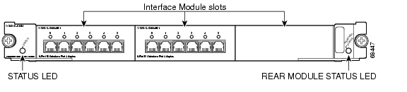
24-Port FXS Analog Interface Module (WS-X6624-FXS)
The 24-port FXS analog interface module (WS-X6624-FXS) interfaces connect directly to standard analog telephones or fax machines. The module interfaces supply ring voltage and dial tone. The module emulates the central office (CO) or private branch exchange (PBX), providing a service to an analog telephone or fax machine. The telephone or fax machine connected through the FXS module operates as if it were connected to a normal CO or PBX line.
The front panel LEDs are shown in Figure 12-5.
Note
Figure 12-5 24-Port FXS Analog Interface Module (WS-X6624-FXS)
When the 24-port FXS analog interface module is powered up, it initializes various hardware components and communicates with the supervisor engine.
The front panel LEDs are described in Table 12-5.
Table 12-5 24-Port FXS Analog Interface Module LEDs
STATUS
Green
The module is online and operational.
Orange
The module is booting or running diagnostics.
The supervisor engine has disabled the module.
The supervisor engine has sent an "SCP_SET_DIAG_FEATURES" message indicating that the diagnostics have failed.
An overtemperature condition has occurred. (A minor temperature threshold has been exceeded during environmental monitoring.)
Red
The module processor powered up but is not running.
The module processor detected a fatal error during its diagnostics.
An overtemperature condition has occurred. (A major temperature threshold has been exceeded during environmental monitoring.)
Off
The module is not receiving power. The module was powered down due to insufficient power. (The module is listed as power-deny in the show module status field.)
Port number
Green
The telephone or fax machine is off-hook.
Yellow
The module or port is disabled through the CLI1 .
Off
The port is not active (connected device is on-hook) or the link is not connected.
1 CLI = command-line interface
![]()
![]()
![]()
![]()
![]()
![]()
![]()
![]()
Posted: Thu Dec 30 00:16:23 PST 2004
All contents are Copyright © 1992--2004 Cisco Systems, Inc. All rights reserved.
Important Notices and Privacy Statement.