|
|

Table Of Contents
Hot Swapping Switching Modules
Power Management and Environmental Monitoring
WS-G5484, WS-G5486, and WS-G5487 Optical GBICs
Coarse Wave Division Multiplexing GBICs
SFP Optical Transceiver Modules
1000BASE-T SFP Transceiver Modules
CWDM SFP Optical Transceiver Modules
XenPak Optical Transceiver Modules
Switch Module Overview
This chapter provides important information about the Catalyst 6000 series and Catalyst 6500 series switching modules. This chapter contains these sections:
•
LEDs
•
•
•
•
This book does not contain instructions for installing the switch chassis, or for installing switching modules in the switch chassis. For information on installing the switch chassis, refer to the Catalyst 6000 Series Switch Installation Guide or the Catalyst 6500 Series Switch Installation Guide. For information on installing switching modules in a switch chassis, refer to the Catalyst 6500 Series Switch Module Installation and Verification Note.
LEDs
The LEDs on the switch module front panel indicate the status of the module. Table 1-1 lists the LEDs and their function.
Port Addresses
Each port (or interface) in the switch is designated by several different types of addresses. The physical interface address is the actual physical location (slot and port) of the interface connector within the chassis. The system software uses the physical addresses to control activity within the switch and to display status information. These physical slot and port addresses are not used by other devices in the network; they are specific to the individual switch and its internal components and software. For more information, see the "Physical Interface Addresses" section.
Note
The Media Access Control (MAC) address is a standardized data link layer address that is required for every port or device that connects to a network. Other devices in the network use these addresses to locate specific ports in the network and to create and update routing tables and data structures. The switches use a unique method, described in the "MAC Addresses" section, to assign and control the MAC addresses of their interfaces.
Physical Interface Addresses
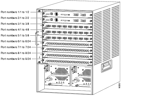
Physical port addresses specify the actual physical location of each module port on the rear of the switch, as shown in Figure 1-1. (The port numbering convention is the same in the 6-slot, 9-slot, and 13-slot chassis.) The address is a two-part number in the format slot/port number. The first number identifies the slot in which the module is installed. Module slots are numbered from top to bottom starting with 1. The second number identifies the physical port number on the module. The port numbers always begin at 1 and are numbered from left to right. The number of additional ports (n/1, n/2, and so on) depends on the number of ports on the module.
Figure 1-1 Catalyst 6009 and Catalyst 6509 Switch Port Address Examples
Interface ports maintain the same addresses regardless of whether other modules are installed or removed. However, when you move a module to a different slot, the first number in the address changes to reflect the new slot number. For example, on a 48-port 10/100BASE-T switching module in slot 2, the address of the left port is 2/1 and the address of the right port is 2/48. If you remove the 48-port 10/100BASE-T switching module from slot 2 and install it in slot 4, the addresses of those same ports become 4/1 through 4/48.
The supervisor engine is n/1 to n/2 because it supports two interfaces: ports 1 and 2. Switching modules are addressed n/1 through n/N.
You can identify each module port by checking its slot and port location on the switch. You can also use software commands to display information about a specific interface, or all interfaces, in the switch. To display information about every interface, enter the show port command without parameters. To display information about a specific interface, enter the show port command with the module (slot) number and port number in the format show port [mod_num/port_num].
MAC Addresses
All network interface connections (ports) require a unique MAC address. The MAC address of an interface is stored in electrically erasable programmable read-only memory (EEPROM) on a component that resides directly on the interface circuitry. The switch system code reads the EEPROM for each interface in the system, learns the MAC addresses, and then initializes appropriate hardware and data structures. Each VLAN in the spanning tree has one unique MAC address. This addressing scheme gives the switch the intelligence to identify the state (connected or not connected) of each interface. When you hot swap a module, the MAC address changes with the module.
Hot Swapping Switching Modules
You can remove and replace switching modules without powering down the switch. This feature is known as hot swapping.
When you remove or insert a switching module while the switch is powered on and operating, the switch does the following:
1.
2.
3.
4.
The switch runs diagnostic tests on any new interfaces. If the test passes, the switch is operating normally. If the new switching module is faulty, the switch resumes normal operation but leaves the new interface disabled.
If the diagnostic test fails, the switch crashes, which usually indicates that the new switching module has a problem in the bus and should be removed.
Caution
For switch module removal and installation procedures, refer to the Catalyst 6500 Series Switch Module Installation and Verification Note.
Power Management and Environmental Monitoring
For detailed information on power management and environmental monitoring, refer to the Catalyst 6500 Series Switch Software Configuration Guide or Catalyst 6500 Series Switch Cisco IOS Software Configuration Guide.
Limiting Connection Distances
The length of your networks and the distances between connections depend on the type of signal, the signal speed, and the transmission media (the type of cabling used to transmit the signals). For example, fiber-optic cable has a greater channel capacity than twisted-pair cabling. The distance and rate limits in this chapter are the IEEE-recommended maximum speeds and distances for signaling. However, if you understand the electrical problems that may arise and can compensate for them, you should get good results with rates and distances greater than those described here, although you do so at your own risk.
Port Connector Requirements
You need these connector types to cable to the switching ports:
•
Note
Note
•
•
•
•
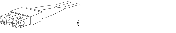
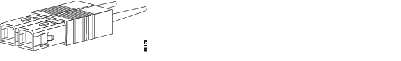
Figure 1-2 SC Fiber-Optic Cable Connector
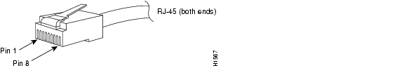
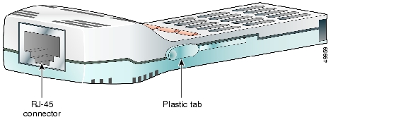
Figure 1-3 RJ-45 Interface Cable Connector
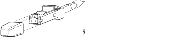
Figure 1-4 MT-RJ Fiber-Optic Cable Connector
Figure 1-5 LC Fiber-Optic Connector
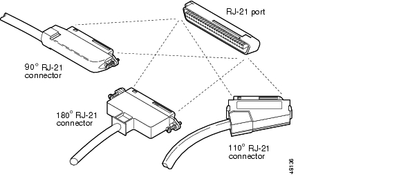
Figure 1-6 RJ-21 Telco Interface Cable Connectors
Port Densities
Table 1-2 lists the bandwidth and port densities of the Catalyst 6000 series and Catalyst 6500 series switches.
Table 1-2 Catalyst 6000 Series and Catalyst 6500 Series Bandwidth and Port Density
Backplane Bandwidth
32 Gbps
32 to 256 Gbps2
Number of Gigabit Ethernet ports
82 (6 slots) Catalyst 6006 switch
130 (9 slots) Catalyst 6009 switch
34 (3 slots) Catalyst 6503 switch
82 (6 slots) Catalyst 6506 switch
130 (9 slots) Catalyst 6509 switch
192 (13 slots) Catalyst 6513 switch
Number of 100BASE-FX Ethernet ports
120 (6 slots) Catalyst 6006 switch
192 (9 slots) Catalyst 6009 switch
48 (3 slots) Catalyst 6503 switch
120 (6 slots) Catalyst 6506 switch
192 (9 slots) Catalyst 6509 switch
288 (13 slots) Catalyst 6513 switch
Number of 10/100 Ethernet ports
240 (6 slots) Catalyst 6006 switch
384 (9 slots) Catalyst 6009 switch
96 (3 slots) Catalyst 6503 switch
240 (6 slots) Catalyst 6506 switch
384 (9 slots) Catalyst 6509 switch
576 (13 slots) Catalyst 6513 switch
Number of 10BASE-FL Ethernet ports
120 (6 slots) Catalyst 6006 switch
192 (9 slots) Catalyst 6009 switch
48 (3 slots) Catalyst 6503 switch
120 (6 slots) Catalyst 6506 switch
192 (9 slots) Catalyst 6509 switch
288 (13 slots) Catalyst 6513 switch
Number of ATM OC-12 ports
5 (6 slots) Catalyst 6006 switch
8 (9 slots) Catalyst 6009 switch
2 (3 slots) Catalyst 6503 switch
5 (6 slots) Catalyst 6506 switch
8 (9 slots) Catalyst 6509 switch
12 (13 slots) Catalyst 6513 switch
Number of FlexWAN Modules
5 (6 slots) Catalyst 6006 switch
8 (9 slots) Catalyst 6009 switch
2 (3 slots) Catalyst 6503 switch
5 (6 slots) Catalyst 6506 switch
8 (9 slots) Catalyst 6509 switch
12 (13 slots) Catalyst 6513 switch
1 Specific combinations of supervisor engines and modules may not be supported in your chassis. Refer to the release notes of the software version running on your system for specific information on modules and supervisor engine combinations that are not supported.
2 If you have backplane bandwidth greater than 32 Gbps, you must install a Switch Fabric Module or install a Supervisor Engine 720 in the Catalyst 6500 series switch chassis.
Gigabit Interface Converters
A Gigabit Interface Converter (GBIC) is a hot-swappable input/output device that plugs into a supervisor engine or Gigabit Ethernet module which links the module with the fiber-optic network or with the copper network.
This section contains these topics:
•
•
WS-G5483 Copper GBIC
The WS-G5483 GBIC uses Category 5, Category 5e, or Category 6 UTP/FTP cable to provide 1000BASE-T full-duplex connectivity between the Gigabit Ethernet module or supervisor engine and the network up to a distance of 328 feet (100 meters). (See Figure 1-7.) Refer to your release notes or the online 1000BASE-T GBIC Switch Compatibility Matrix posted with the GBIC documentation on Cisco.com for the list of modules and the required software release level necessary to support this GBIC.
Caution
Figure 1-7 Copper GBIC (WS-G5483)
WS-G5484, WS-G5486, and WS-G5487 Optical GBICs
Table 1-3 lists the three types of optical GBICs.
Table 1-3 Optical GBIC Model List
WS-G5484
Short wavelength (1000BASE-SX)
WS-G5486
Long wavelength/long haul (1000BASE-LX/LH)
WS-G5487
Extended distance (1000BASE-ZX)
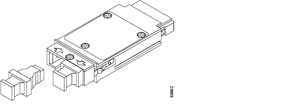
Each of the three types of optical GBICs comes in two physical models shown in Figure 1-8. These two physical models require different installation procedures.
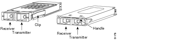
Figure 1-8 Optical GBIC Physical Styles (WS-G5484, WS-G5486, and WS-G5487)
Coarse Wave Division Multiplexing GBICs
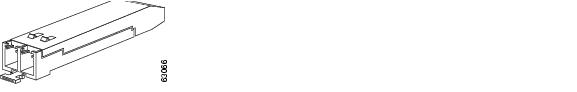
Eight GBICs are available for use with the CWDM Passive Optical System. (See Figure 1-9.) Table 1-4 lists the available GBICs. These eight GBICs are installed in the Catalyst 6500 series modules that support GBICs and are used with the CWDM Passive Optical System. For more information on the CWDM Passive Optical System, refer to the Installation Note for the Cisco CWDM Passive Optical System.
Figure 1-9 CWDM GBIC
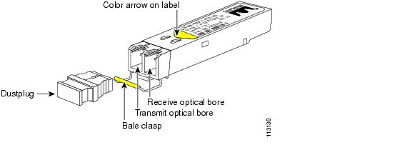
SFP Optical Transceiver Modules
Small Form-Factor Pluggable (SFP) optical transceiver modules are hot-pluggable and field-replaceable, and you can insert them into SFP module slots on the front panel of the Supervisor Engine 720 and the WS-X6724-SFP Gigabit Ethernet module. The SFP optical transceiver modules use an LC connector.
You can use any combination of SFP modules that your Cisco device supports. The only restrictions are that each SFP port must match the wavelength specifications on the other end of the cable and that the cable must not exceed the stipulated cable length for reliable communications.
Figure 1-10 SFP Optical Transceiver Module
Table 1-5 SFP Optical Transceiver Module Cabling Specifications
1000BASE-SX
(GLC-SX-MM)850
MMF
62.5
62.5
50.0
50.0160
200
400
500722 feet (220 m)
902 feet (275 m)
1640 feet (500 m)
1804 feet (550 m)1000BASE-LX/LH
GLC-LH-SM)1300
MMF1
SMF62.5
50.0
50.0
9/10500
400
500
—1804 feet (550 m)
1804 feet (550 m)
1804 feet (550 m)
32,810 feet (10 km)1000BASE-ZX
(GLC-ZX-SM)1550
SMF
9/10
—
43.4 to 62 miles (70 to 100 km)2
1 A mode-conditioning patch cord is required. Using an ordinary patch cord with MMF, 1000BASE-LX/LH SFP modules, and a short link distance can cause transceiver saturation, resulting in an elevated bit error rate (BER). When using the LX/LH SFP module with 62.5-micron diameter MMF, you must also install a mode-conditioning patch cord between the SFP module and the MMF cable on both the sending and receiving ends of the link. The mode-conditioning patch cord is required for link distances greater than 984 feet (300 m).
2 1000BASE-ZX SFP modules can reach up to 100 km by using dispersion-shifted SMF or low-attenuation SMF; the distance depends on the fiber quality, the number of splices, and the connectors.
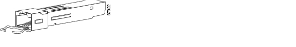
1000BASE-T SFP Transceiver Modules
The 1000BASE-T SFP transceiver modules provide Category 5, Category 5e, and Category 6 support for SFP modules. The 1000BASE-T SFP transceiver modules use standard four twisted-pair cable at lengths up to 328 feet (100 meters) and have standard RJ-45 connectors. Figure 1-11 shows a 1000BASE-T SFP module.
Figure 1-11 1000BASE-T SFP Transceiver Module
CWDM SFP Optical Transceiver Modules
The Coarse Wavelength Division Multiplexing (CWDM) SFP optical transceiver modules are hot-swappable, and can be plugged into standard receptacles in switching modules that convert Gigabit Ethernet electrical signals into a single-mode fiber-optic (SMF) interface. You can connect the CWDM SFPs to CWDM passive optical system optical add/drop multiplexer (OADM) modules or multiplexer/demultiplexer plug-in modules using single-mode fiber-optic cables with standard SC connectors. Table 1-6 lists the available CWDM SFP wavelengths and color-coding identifier.
Figure 1-12 shows a CWDM SFP with the optical port dust plug removed.
Figure 1-12 CWDM SFP Optical Transceiver Module
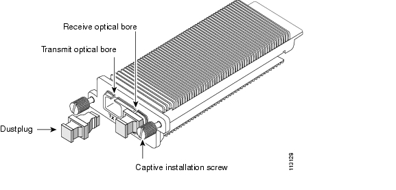
XenPak Optical Transceiver Modules
The XenPak optical transceiver modules are hot-swappable, transceiver components that you can plug into standard receptacles in modules that convert Gigabit Ethernet electrical signals into a single-mode fiber-optic (SMF) interface. Figure 1-13 shows a XenPak optical transceiver module.
Figure 1-13 XenPak Optical Transceiver Module
Table 1-7 lists the available XenPak transceiver modules and their specifications.
Software Requirements
For information on the minimum, recommended, and default software versions for the Catalyst 6000 series and Catalyst 6500 series switches, supervisor engines, and modules, refer to the applicable release notes for the latest maintenance release of your software.
![]()
![]()
![]()
![]()
![]()
![]()
![]()
![]()
Posted: Thu Dec 30 00:08:58 PST 2004
All contents are Copyright © 1992--2004 Cisco Systems, Inc. All rights reserved.
Important Notices and Privacy Statement.