|
|

This publication contains procedures to upgrade your Route Switch Module (RSM) dynamic random-access memory (DRAM) and also contains detailed information on using Flash memory (PCMCIA) cards.
 |
Note You can access all Catalyst 5000 family documentation at the World Wide Web locations listed in the "Obtaining Documentation" section on page 12. |
This publication consists of these sections:
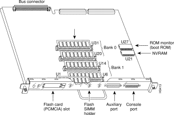
The DRAM resides on up to four SIMMs on the RSM. The DRAM SIMM sockets are U31 and U20 for bank 0, and U14 and U6 for bank 1. The default DRAM configuration is 32 MB (two 16-MB SIMMs in bank 0 with bank 1 left empty). (See Figure 1.)
|
Note The total number of memory devices per SIMM differs for each manufacturer. The SIMMs in the following illustrations are generic representations of the actual DRAM SIMMs for your RSM. |
This section describes the steps for increasing the amount of DRAM by replacing up to four SIMMs that you obtain from an approved vendor.
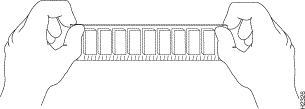
The SIMM sockets use the thumb tabs that are often used in PCs and other computer equipment. Each RSM SIMM socket has two metal retaining springs, one at each end. (See Figure 2.) When a SIMM is fully seated in the socket, the retaining springs snap over the ends of the SIMM to lock it in the socket.
lists the various configurations of DRAM SIMMs that are available. Note that you must have either 32-MB, 64-MB, or 128-MB DRAM; you cannot use any other combinations. SIMMs must be 60 ns or faster and no taller than one inch.
Table 1 DRAM SIMM Configurations
| DRAM Bank 0 | Quantity | DRAM Bank 1 | Quantity | Total DRAM |
Place removed SIMMs on an antistatic mat and store them in an antistatic bag. You can use the SIMMs that you remove in compatible equipment.
Follow these steps to remove the existing SIMMs:
 |
Caution To prevent ESD damage, handle SIMMs by the card edges only. |
|
Caution When removing or inserting the RSM, always wear an electrostatic discharge (ESD) wrist strap connected to the ESD wrist strap connector located beneath the Catalyst switch power supplies. |
Step 2 The RSM is secured with two captive installation screws. Use a 1/4-inch flat-blade screwdriver to loosen the captive installation screws, and then remove the RSM using the ejector levers. Place the RSM on an antistatic mat.
Step 3 Position the RSM so that the front panel is away from you and the edge connector is toward you.
Step 4 Locate the SIMMs. The DRAM SIMMs occupy U31 and U20 in bank 0, and U14 and U6 in bank 1. (See Figure 1.)
Step 5 Release the spring clips from the SIMM that you want to remove and release the SIMM from the socket. (See Figure 2.)

Step 6 When both ends of the SIMM are released from the socket, grasp the ends of the SIMM with your thumb and forefinger and pull the SIMM completely out of the socket. Handle the edges of the SIMM only; avoid touching the memory module or pins, and the metal traces, or fingers, along the socket edge.
Step 7 Place the SIMM in an antistatic bag.
Step 8 Repeat Steps 4 through 7 for the remaining SIMMs, as required for your upgrade.
This completes the SIMM removal procedure. Proceed to the next section to install the new SIMMs.
Following is the procedure for installing new SIMMs.
|
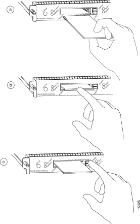
Caution SIMMs are sensitive components that are susceptible to ESD damage. Handle SIMMs by the edges only; avoid touching the memory modules, pins, or traces (the metal fingers along the connector edge of the SIMM). (See Figure 3.) |
Follow these steps to install the new SIMMs:
Step 2 Remove a new SIMM from the antistatic bag.
Step 3 Hold the SIMM component side up, with the connector edge (the metal fingers) closest to you. Hold the sides of the SIMM between your thumb and middle finger, with your forefinger against the far edge, opposite the connector edge. (See Figure 3.)
Step 4 Tilt the SIMM to approximately the same angle as the socket and insert the entire connector edge into the socket. (Install the first SIMM in the slot farthest away from you. Install the last SIMM in the slot closest to you.)
|
Caution When inserting SIMMs, use firm but not excessive pressure. If you damage a socket, the RSM has to be shipped back to the factory for repair. |
Step 5 Gently push the SIMM into the socket until the spring clips snap over the ends of the SIMM. If necessary, rock the SIMM gently back and forth to seat it properly.
Step 6 Repeat Steps 2 through 5 for the remaining SIMMs.
Step 7 When all SIMMs are installed, check all alignment holes (two on each SIMM) and ensure that the spring retainer is visible. If it is not, the SIMM is not seated properly. If any SIMM appears misaligned, carefully remove it and reseat it in the socket. Push the SIMM firmly back into the socket until the retainer springs snap into place.
Step 8 Guide the RSM back into the switch slot, aligning the sides of the RSM with the guides in the slot (avoid touching the components on the RSM). While keeping the RSM oriented horizontally, carefully slide it into the slot until its front panel contacts the ejector levers.
Step 9 Using the thumb and forefinger of each hand, simultaneously push the left lever and the right lever in to fully seat the RSM in the backplane connector.
|
Caution Always use the ejector levers when installing or removing modules. A module that is partially seated in the backplane causes the system to halt and subsequently crash. |
Step 10 Use a screwdriver to tighten the captive installation screws on the left and right sides of the module.
Step 11 Check the status of the module as follows:
If the system fails to boot properly, or if the console terminal displays a checksum or memory error, check the following:
If after several attempts the system fails to restart properly, contact a service representative for assistance. Before you call, make note of any error messages, unusual LED states, or any other indications that might help solve the problem.
|
Note The time required for the system to initialize varies with different router configurations. Routers with 128-MB DRAM take longer to boot than those with 32-MB DRAM. |
This completes the SIMM replacement procedure.
|
Note The Flash memory cards are available in two sizes: 16 MB and 20 MB. |
The Flash memory (PCMCIA) card slots on the front panel of the RSM are for additional PCMCIA-based Flash memory. You can use this Flash memory to store and run Cisco IOS images, or as a file server for other routers to access as clients. Occasionally, it might be necessary to remove and replace Flash memory cards; however, removing Flash memory cards is not required and is not recommended after the cards are installed in the slots.
It might become necessary for you to replace or install a Flash memory card in your RSM. The RSM has two PCMCIA slots: slot 0 (bottom) and slot 1 (top). (See Figure 4.) The following procedure is generic and can be used for a Flash memory card in either slot position.
|
Note The Flash memory card can be inserted and removed with the power on. |
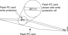
Before you install a card, verify that the Flash memory card is set with write protection off. The write protect switch is located on the front edge of the card when oriented with the printing right side up and the edge connector end away from you. (See Figure 5.)
Following is the procedure for installing and removing a Flash memory card:
Step 2 Insert the card into the appropriate slot until the card completely seats in the connector at the back of the slot and the eject button pops out toward you. Note that the card does not insert all the way inside the RSM; a portion of the card remains outside the slot. Do not attempt to force the card past this point.
Step 3 To eject a card, press the appropriate ejector button until the card is free of the connector at the back of the slot.
Step 4 Remove the card from the slot and place it in an antistatic bag.
The Flash memory (PCMCIA) card that shipped with your RSM contains the Cisco IOS software image. In some cases, you might need to insert a new Flash memory card and copy images or back up configuration files onto it. Before you can use a new Flash memory card, you must format it.
PCMCIA Flash memory cards must either be formatted on the RSM or on an RSP-based 7500 series router running software at the same level, or greater, as the RSM. Flash memory cards previously formatted on an RP-based Cisco 7000 series router cannot be used on the RSM. Note that Flash memory cards formatted on the RSM can be used on RSP-based 7500 series routers (but not on RP-based 7000 series routers).
|
Note The following procedure assumes you have already booted the RSM. |
 |
Warning The following formatting procedure erases all information on the Flash memory card. To prevent the loss of important data on a Flash memory card, proceed carefully. If you wish to save the data on a Flash memory card, upload the data to a server before you format the card. |
Use the following procedure to format a new Flash memory card:
Step 2 To format the Flash memory card, use the format slot0: (or format slot1:) command as follows. (Use only Intel Series 2+ Flash memory cards.)
|
Note For this example, a 16-MB Flash memory card was used, and at the line "Formatting sector," the system counted the card sectors backwards from 128 to 1 as it formatted them. For 20-MB Flash memory cards, the system counts backwards from 160 to 1. |
The new Flash memory card is now formatted and ready to use.
Use the following series of commands to make the image (the file named new.image) bootable. Note that, since the configuration register must be set to 0x2102, the config-register command is part of the sequence.
When the system reloads, it will boot the image new.image from the Flash memory card in slot 0.
With the Flash memory card formatted, you can now copy a bootable image into it. To copy an image, use the following procedure, which assumes the following:
|
Note To assure access to a TFTP sever, you need to configure at least one interface using the setup command facility. For instructions on using this procedure, refer to the Configuration Fundamentals Configuration Guide. |
Following is the procedure for copying a bootable file (called new.image) into the Flash memory card:
Step 2 Insert an unformatted Flash memory card and format it using the procedure in "Formatting a Flash Memory Card," and then proceed to Step 3.
|
Note If you have already formatted a Flash memory card, you can use it instead; however, you cannot boot from or use a Flash memory card formatted on another type of system. You must reformat it to use it as a boot or storage source. |
Step 3 To enable the RSM, copy the image new.image to the Flash memory card, make this image in the Flash memory card (in slot 0) the default boot image, and reboot the RSM, using the following series of commands:
|
Note In the preceding example, the exclamation points (!!!) appear as the file is downloaded and the "C" characters signify calculation of the checksum, which is a verification that the file has been correctly downloaded to the Flash memory card. |
When the system reloads, it boots the image new.image from the Flash memory card in slot 0.
As future releases of Cisco IOS images become available, you receive these images either as a netbooted file, a file on floppy disk, or a file on a Flash memory card.
The following scenario describes how to use a newly released image on a Flash memory card in a system that has an older image on a Flash memory card in slot 0 (and a default boot image in the onboard Flash SIMM).
For this scenario, the filenames are as follows:
Copy the new image from the new Flash memory card onto the Flash memory card with the old image.
|
Note This scenario assumes that the new image will fit on the Flash memory card in slot 0, next to the old image. If there is not enough available space, use the delete command to delete files to make sufficient room for the new image; however, do not delete the image.old file. Then use the squeeze command to remove these deleted files from the Flash memory card. If, after you have deleted files and used the squeeze command, the two files cannot coexist on the Flash memory card in slot 0, remove this card (place it in an anti-static bag and store it in a safe place), and then insert the new Flash memory card (with the file image.new) in slot 0. Proceed to Step 5 and use the command boot system flash slot0:image.new to designate the file image.new as the default boot image. |
Step 2 Enable the RSM as follows:
Step 3 Insert the new Flash memory card in slot 1.
Step 4 Use the following command to copy the file image.new in slot 1 to the Flash memory card in slot 0 only if there is enough memory space for the two images to coexist. If there is not enough memory space, proceed to Step 5.
|
Note The previous command can also be entered as copy slot1:image.new slot0:. |
Step 5 Use the following series of commands to designate the file image.new (which is in the Flash memory card in slot 0) as the default boot image:
When the system reloads, it boots the file image.new from the Flash memory card in slot 0.
A locked block of Flash memory occurs when power is lost or a Flash memory card is unplugged during a write or erase operation. When a block of Flash memory is locked, it cannot be written to or erased, and the operation consistently fails at a particular block location. The only way to recover from locked blocks is by reformatting the Flash memory card with the format command.
|
Caution Formatting a Flash memory card causes existing data to be lost. |
The following documents are available for the Catalyst 5000 family switches:
The following sections provide sources for obtaining documentation from Cisco Systems.
You can access the most current Cisco documentation on the World Wide Web at the following sites:
Cisco documentation and additional literature are available in a CD-ROM package, which ships with your product. The Documentation CD-ROM is updated monthly and may be more current than printed documentation. The CD-ROM package is available as a single unit or as an annual subscription.
Cisco documentation is available in the following ways:
http://www.cisco.com/cgi-bin/order/order_root.pl
http://www.cisco.com/go/subscription
If you are reading Cisco product documentation on the World Wide Web, you can submit technical comments electronically. Click Feedback in the toolbar and select Documentation. After you complete the form, click Submit to send it to Cisco.
You can e-mail your comments to bug-doc@cisco.com.
To submit your comments by mail, use the response card behind the front cover of your document, or write to the following address:
Attn Document Resource Connection
Cisco Systems, Inc.
170 West Tasman Drive
San Jose, CA 95134-9883
Cisco provides Cisco.com as a starting point for all technical assistance. Customers and partners can obtain documentation, troubleshooting tips, and sample configurations from online tools. For Cisco.com registered users, additional troubleshooting tools are available from the TAC website.
Cisco.com is the foundation of a suite of interactive, networked services that provides immediate, open access to Cisco information and resources at anytime, from anywhere in the world. This highly integrated Internet application is a powerful, easy-to-use tool for doing business with Cisco.
Cisco.com provides a broad range of features and services to help customers and partners streamline business processes and improve productivity. Through Cisco.com, you can find information about Cisco and our networking solutions, services, and programs. In addition, you can resolve technical issues with online technical support, download and test software packages, and order Cisco learning materials and merchandise. Valuable online skill assessment, training, and certification programs are also available.
Customers and partners can self-register on Cisco.com to obtain additional personalized information and services. Registered users can order products, check on the status of an order, access technical support, and view benefits specific to their relationships with Cisco.
To access Cisco.com, go to the following website:
The Cisco TAC website is available to all customers who need technical assistance with a Cisco product or technology that is under warranty or covered by a maintenance contract.
If you have a priority level 3 (P3) or priority level 4 (P4) problem, contact TAC by going to the TAC website:
P3 and P4 level problems are defined as follows:
In each of the above cases, use the Cisco TAC website to quickly find answers to your questions.
To register for Cisco.com, go to the following website:
http://www.cisco.com/register/
If you cannot resolve your technical issue by using the TAC online resources, Cisco.com registered users can open a case online by using the TAC Case Open tool at the following website:
http://www.cisco.com/tac/caseopen
If you have a priority level 1(P1) or priority level 2 (P2) problem, contact TAC by telephone and immediately open a case. To obtain a directory of toll-free numbers for your country, go to the following website:
http://www.cisco.com/warp/public/687/Directory/DirTAC.shtml
P1 and P2 level problems are defined as follows:
![]()
![]()
![]()
![]()
![]()
![]()
![]()
![]()
Posted: Sat Jan 18 13:28:28 PST 2003
All contents are Copyright © 1992--2002 Cisco Systems, Inc. All rights reserved.
Important Notices and Privacy Statement.