|
|

Product Number: WS-C5097(=)
This installation note contains instructions on how to install the Catalyst family of switches in a telco-style rack using the center rack-mount kit, WS-C5097(=).
For a complete description of switch hardware installation and maintenance procedures, refer to the appropriate hardware installation guide.
Cisco documentation and additional literature are available in a CD-ROM package, which ships with your product. The Documentation CD-ROM, a member of the Cisco Connection Family, is updated monthly. Therefore, it might be more current than printed documentation. To order additional copies of the Documentation CD-ROM, contact your local sales representative or call customer service. The CD-ROM package is available as a single package or as an annual subscription. You can also access Cisco documentation on the World Wide Web at http://www.cisco.com, http://www-china.cisco.com, or http://www-europe.cisco.com.
If you are reading Cisco product documentation on the World Wide Web, you can submit comments electronically. Click Feedback in the toolbar and select Documentation. After you complete the form, click Submit to send it to Cisco. We appreciate your comments.
This document contains the following sections:
This section provides safety recommendations you need to be aware of as you use the center rack-mount kit to install your switch in a telco-style rack. Also included in this section are center rack-mounting guidelines and a list of tools you need to perform kit installation.
Safety recommendations appear throughout this installation note in procedures that, if performed incorrectly, may harm you. A warning symbol precedes each warning statement.
 | Warning This warning symbol means danger. You are in a situation that could cause bodily injury. Before you work on any equipment, be aware of the hazards involved with electrical circuitry and be familiar with standard practices for preventing accidents. To see translations of the warnings that appear in this publication, refer to the appendix "Translated Safety Warnings" in the appropriate hardware installation guide. |
Before center rack-mounting the switch, ensure the following:
 | Warning To prevent bodily injury when mounting or servicing this unit in a rack, you must take special precautions to ensure that the system remains stable. The following guidelines are provided to ensure your safety: |
 | Warning To prevent the switch from overheating, do not operate it in an area that exceeds the maximum recommended ambient temperature of 104°F (40°C). To prevent airflow restriction, allow at least 3 inches (7.6 cm) of clearance around the ventilation openings. |
The switch chassis is not intended to be moved frequently. Before you install the chassis, ensure that your site is properly prepared. Proper preparation keeps you from having to move the chassis later to accommodate power sources and network connections.
A minimum of two people are required to lift a chassis. Whenever you lift the chassis or any heavy object, follow these guidelines:
You will need the following tools to install the center rack-mount kit on your five-slot chassis. If you need additional parts or assistance, contact your technical support representative.
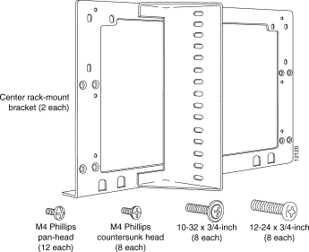
The contents of the center rack-mount kit, WS-C5097(=), are shown in Figure 1 and listed in Table 1.
| Quantity | Part Description and Usage |
|---|---|
2 | Mounting bracket. There is one left-side mounting bracket and one right-side mounting bracket included in the kit. One bracket is attached to each side of the switch chassis using M4 screws. |
8 | M4 x 10-mm Phillips countersunk-head screws. Used to attach the center rack-mount brackets to the five-slot chassis. |
12 | M4 x 12-mm Phillips pan-head screws. Used to attach the center rack-mount brackets to the 9- and 13-slot chassis. |
8 | 10-32 x 3/4-inch Phillips binder-head screws. Used to attach the center rack-mount brackets to a telco-style rack. |
8 | 12-24 x 3/4-inch Phillips binder-head screws1. Used to attach the center rack-mount brackets to a telco-style rack. |
| 112-24 x 3/4-inch screws are provided in the center rack-mount kit if your telco-style rack requires their use. |
Perform this procedure to center rack-mount a five-slot chassis in a telco-style rack.
Step 1 Prepare for installation as follows:
(a) Place the chassis on the floor or on a sturdy table as close as possible to the rack with enough clearance to allow you to move around the chassis.
(b) Measure the space between the inner edges of the left and right mounting posts to ensure that it is 17.75 inches (45.09 cm) wide. (The chassis is 17.25 inches [43.8 cm] wide and must fit between the mounting posts.)
(c) Open the center rack-mount kit. Check the kit contents list in Table 1 to verify that all parts are included.
Step 2 Perform these steps to attach the center rack-mount brackets to the five-slot chassis.
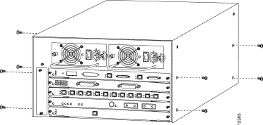
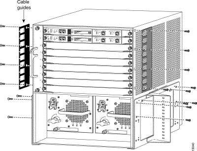
(a) Remove eight M4 pan-head screws from the switch side cover panels (see Figure 2).
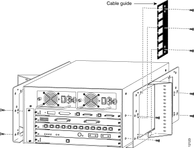
(b) Position one bracket on the chassis as shown in Figure 3.
(c) Attach the bracket to the chassis with four M4 Phillips countersunk-head screws supplied with the center rack-mount kit.
(d) Repeat Steps b and c for the second bracket.
(e) Attach the cable guide, if needed, using three M3 screws provided in the cable management kit that you received in the accessories box shipped with your switch. Attach the cable guide to the right side center rack-mount bracket to prevent the cables from obscuring module LEDs (see Figure 3).
Step 3 Perform these steps to install the chassis in the rack. You should have a third person assist you with this step.
 | Warning Two people are required to lift the chassis. Grasp the chassis underneath the lower edge and lift with both hands. To prevent injury, keep your back straight and lift with your legs, not your back. To prevent damage to the chassis and components, never attempt to lift the chassis with the handles on the power supplies. These handles were not designed to support the weight of the chassis. |
(a) With a person standing at each side of the chassis, grasp the bottom edge of the chassis with one hand near the front and the other near the back. Slowly lift the chassis in unison. Avoid sudden twists or moves to prevent injury.
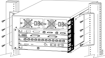
(b) Align the mounting holes in the mounting bracket with the mounting holes in the telco-style rack. Make sure that the chassis is level in the rack.
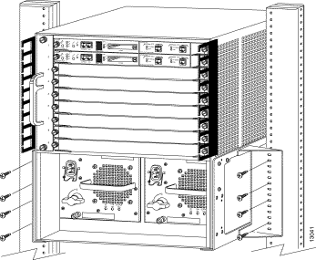
(c) Secure the chassis by using eight (four per side) 10-32 or 12-24 screws through the elongated holes in the mounting bracket and the threaded holes in the telco-style rack post as shown in Figure 4.
Use this procedure to center rack-mount a nine-slot chassis in a telco-style rack.
Step 1 Prepare for installation as follows:
(a) Place the chassis on the floor or on a sturdy table as close as possible to the rack with clearance to allow you to move around the chassis.
(b) Measure the space between the inner edges of the left and right mounting posts to ensure that it is 17.75 inches (45.09 cm) wide. (The chassis is 17.25 inches [43.8 cm] wide and must fit between the mounting posts.)
(c) Measure the vertical space in the rack. Ensure that there is at least 20 inches (50.8 cm) of space to install the chassis.
(d) Open the center rack-mount kit. Check the kit contents list in Table 1 to verify that all parts are included.
Step 2 Perform these steps to attach the center rack-mount brackets to the nine-slot chassis:
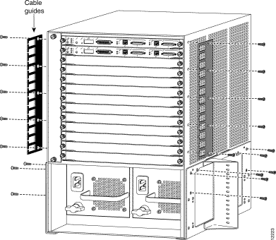
(a) Position one of the brackets on the chassis as shown in Figure 5.
(b) Attach the bracket to the chassis with six M4 Phillips pan-head screws.
 | Caution To prevent possible damage to the switch, make sure that the bottom of the chassis is resting on the center rack-mount bracket rail before you tighten the six screws. |
(c) Repeat Steps a and b for the second bracket.
(d) Attach the cable guides, if needed, using eight M3 screws (four for each cable guide) provided in the cable management kit that you received in the accessories box shipped with your switch. Attach the cable guides to the chassis above the center rack-mount brackets (see Figure 5).
Step 3 Perform these steps to install the nine-slot chassis in the telco-style rack. You should have a third person assist you with this step.
 | Warning Two people are required to lift the chassis. Grasp the chassis underneath the lower edge and lift with both hands. To prevent injury, keep your back straight and lift with your legs, not your back. To prevent damage to the chassis and components, never attempt to lift the chassis with the handles on the power supplies. These handles were not designed to support the weight of the chassis. |
(a) With a person standing at each side of the chassis, grasp the bottom edge of the chassis with one hand near the front and the other near the back. Slowly lift the chassis in unison. Avoid sudden twists or moves to prevent injury.
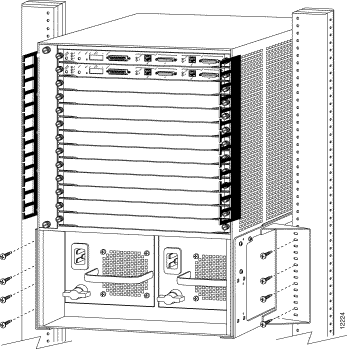
(b) Position the chassis in the rack as shown in Figure 6.
(c) Align the mounting holes in the two brackets with the mounting holes in the telco-style rack. Make sure the chassis is level in the rack.
(d) While two people support the chassis in the rack, a third person should install eight (four per side) 10-32 or 12-24 screws through the elongated holes in the mounting bracket and into the threaded holes in the telco-style rack post as shown in Figure 6.
Use this procedure to center rack-mount a 13-slot chassis in a telco-style rack.
Step 1 Prepare for installation as follows:
(a) Place the chassis on the floor or on a sturdy table as close as possible to the rack with clearance to allow you to move around the chassis.
(b) Measure the space between the inner edges of the left and right mounting posts to ensure that it is 17.75 inches (45.09 cm) wide. (The chassis is 17.25 inches [43.8 cm] wide and must fit between the mounting posts.)
(c) Measure the vertical space in the rack. Ensure that there is at least 30 inches (76.2 cm) of space to install the chassis.
(d) Open the center rack-mount kit. Check the kit contents list in Table 1 to verify that all parts are included.
Step 2 Perform these steps to attach the center rack-mount brackets to the 13-slot chassis.
(a) Position one of the brackets on the chassis as shown in Figure 7.
(b) Attach the bracket to the chassis with six M4 Phillips pan-head screws.
 | Caution To prevent possible damage to the switch, make sure that the bottom of the chassis is resting on the center rack-mount bracket rail before you tighten the six screws. |
(c) Repeat Steps a and b for the second bracket.
(d) Attach the cable guides, if needed, using ten M3 screws (five for each cable guide) provided in the cable management kit that you received in the accessories box shipped with your switch. Attach the cable guides to the chassis above the center rack-mount brackets (see Figure 7).
Step 3 Perform these steps to install the 13-slot chassis in the telco-style rack.You should have a third person assist you with this step.
 | Warning Two people are required to lift the chassis. Grasp the chassis underneath the lower edge and lift with both hands. To prevent injury, keep your back straight and lift with your legs, not your back. To prevent damage to the chassis and components, never attempt to lift the chassis with the handles on the power supplies. These handles were not designed to support the weight of the chassis. |
(a) With a person standing at each side of the chassis, grasp the bottom edge of the chassis with one hand near the front and the other near the back. Slowly lift the chassis in unison. Avoid sudden twists or moves to prevent injury.
(b) Position the chassis in the rack as shown in Figure 8.
(c) Align the mounting holes in the two brackets with the mounting holes in the telco-style rack. Make sure the chassis is level in the rack.
(d) While two people support the chassis in the rack, a third person should install eight (four per side) 10-32 or 12-24 screws through the elongated holes in the mounting bracket and into the threaded holes in the telco-style rack post as shown in Figure 8.
Cisco Connection Online (CCO) is Cisco Systems' primary, real-time support channel. Maintenance customers and partners can self-register on CCO to obtain additional information and services.
Available 24 hours a day, 7 days a week, CCO provides a wealth of standard and value-added services to Cisco's customers and business partners. CCO services include product information, product documentation, software updates, release notes, technical tips, the Bug Navigator, configuration notes, brochures, descriptions of service offerings, and download access to public and authorized files.
CCO serves a wide variety of users through two interfaces that are updated and enhanced simultaneously: a character-based version and a multimedia version that resides on the World Wide Web (WWW). The character-based CCO supports Zmodem, Kermit, Xmodem, FTP, and Internet e-mail, and it is excellent for quick access to information over lower bandwidths. The WWW version of CCO provides richly formatted documents with photographs, figures, graphics, and video, as well as hyperlinks to related information.
You can access CCO in the following ways:
For a copy of CCO's Frequently Asked Questions (FAQ), contact cco-help@cisco.com. For additional information, contact cco-team@cisco.com.

|
|