|
|

Product Numbers: WS-X5403(=), WS-X5410(=), WS-G5484(=), WS-G5486(=), WS-G5487(=)
This configuration note describes how to install and configure the Catalyst 5000 series three-port Gigabit Ethernet switching module and the nine-port Gigabit EtherChannel switching module. The following products are covered in this configuration note:
For a complete description of commands to configure and maintain Catalyst 5000 series switches, refer to the Software Configuration Guide for your switch and the Command Reference for your switch. For complete switch hardware configuration and maintenance procedures, refer to the Catalyst 5000 Series Installation Guide. For information on Catalyst 5000 series switching modules, refer to the Catalyst 5000 Series Module Installation Guide. These documents are available on the Cisco Connection Documentation, and in print.
This document contains these sections:
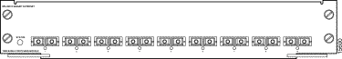
Table 1 describes the Catalyst 5000 series Gigabit Ethernet and Gigabit EtherChannel modules. The Gigabit Ethernet module is shown in Figure 1; the Gigabit EtherChannel Switching Module is shown in Figure 2.
| Model | Module | Description |
|---|---|---|
Nine switched 1000-Mbps full-duplex ports1 |
| 1The modules use interchangeable Gigabit Interface Converters (GBICs) to interface between the network's optical fiber and the module ports. Three GBIC types are available: a 1000BaseSX, a 1000BaseLX/LH, and a 1000BaseZX. All three GBICs use SC-type connectors. |
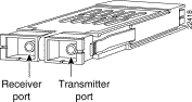
A gigabit interface converter (GBIC) (see Figure 3) is a hot-swappable input/output (transceiver) device that plugs into a module's Gigabit Ethernet port, linking the port with the fiber-optic network. The following GBIC types are supported:
Note Cisco 1000BaseLX/LH interfaces fully comply with the IEEE 802.3z 1000BaseLX standard. However, their higher optical quality allows them to reach 10 km over single-mode fiber (SMF) versus the 5 km specified in the standard.
Note Due to interoperability issues, Cisco does not support GBICs purchased from third-party vendors.
For GBIC installation information, refer to the "GBIC Handling Guidelines and Installation" section.
For GBIC cabling distance information, refer to the "GBIC Cabling Distances" section.
Table 2 describes the LEDs on the Gigabit Ethernet and Gigabit EtherChannel switching modules.
| LED | State | Description |
|---|---|---|
The switch performs a series of self-tests and diagnostic tests. |
||
System boot, self-test diagnostics running, or the module is disabled. |
||
| 1On the Gigabit Ethernet switching module (WS-X5403), the individual port LEDs are labeled as LINK. |
This section lists the specifications for the Catalyst 5000 series Gigabit Ethernet and Gigabit EtherChannel switching modules. Specifications included are standards compliance, module specifications, and cabling distances.
Catalyst 5000 series Gigabit Ethernet and Gigabit EtherChannel switching modules comply with the standards listed in Table 3.
| 1UL = Underwriters Laboratories
2CSA = Canadian Standards Association 3EN = Europäische Norm 4IEC = International Electrotechnical Commission 5TS = Technical Standard 6AS/NZS = Australian/New Zealand Standard 7EMI = electromagnetic interference 8FCC = Federal Communications Commission 9ICES = Interference-Causing Equipment Standard 10FTP = foil twisted-pair |
Table 4 lists the specifications for the Gigabit Ethernet and Gigabit EtherChannel switching modules.
| Specification | Description |
|---|---|
WS-X5403—1.18 x 15.51 x 16.34 in. (30 x 394 x 415 mm) |
|
Gigabit Ethernet module (WS-X5403): 18 MB (6 MB per port) |
|
Station-to-station cabling distance is dependent on the type of GBIC installed. Refer to Table 5 for a summary of cabling distance versus GBIC type. |
|
Cisco Discovery Protocol, Ethernet MIB3 (RFC 1398), Interface Table (RFC 1573), Bridge MIB (RFC 1493), Ethernet Repeater MIB (RFC 1516), RMON4 MIB (RFC 1757), Cisco Workgroup MIB, and Cisco VLAN Trunk Protocol |
| 1The Gigabit EtherChannel switching module (WS-X5410) occupies two slots in the switch chassis.
2All GBIC types have SC connectors. 3MIB = Management Interface Base 4RMON = Remote Monitoring |
Table 5 lists the recommended maximum station-to-station cabling distances for the three types
of GBICs.
| GBIC | Wavelength (nm) | Fiber Type | Core Size (um) | Modal Bandwidth (MHz.km) | Cable Distance |
|---|---|---|---|---|---|
| 1MMF=multimode fiber
2Mode-conditioning patch cord (CAB-GELX-625) is required. 3SMF=single-mode fiber. 4Dispersion-shifted single-mode fiber-optic cable required for 100 km distance. |
You must observe the following optical-fiber cabling restrictions when using GBICs:
Safety warnings appear throughout this publication in procedures that, if performed incorrectly, may harm you. A warning symbol precedes each warning statement.
Use the following guidelines to ensure your safety and protect the equipment. This list does not include all potentially hazardous situations during installation, so be alert.
When working with electrical equipment, exercise these basic safety guidelines:
Use the following safety rules when working with any equipment that is disconnected from a power source but still connected to telephone wiring or other network cabling:
Electrostatic discharge (ESD) damage occurs when electronic boards or components are improperly handled. ESD can result in complete or intermittent failures of electronic components.
Guidelines for preventing ESD damage are as follows:
All Catalyst 5000 series switches support hot swapping, which lets you install, remove, replace, and rearrange switching modules without turning off the system power. When the system detects that a switching module has been installed or removed, it runs diagnostic and discovery routines automatically, acknowledges the presence or absence of the module, and resumes system operation with no operator intervention.
Depending on the system and placement of the Gigabit Ethernet switching module in the system's backplane, not all of the module ports may be active. Table 6 lists the Catalyst 5000 series switches and the Gigabit Ethernet switching-module ports that are available when the module is installed in that switch.
To maximize Gigabit EtherChannel switching module operation, connect the module to all three 1.2-Gb buses on the Catalyst 5505, Catalyst 5509, and Catalyst 5500 switch backplanes (the Catalyst 5000 switch has only one 1.2-Gb bus). See Table 7 for slot requirements.
Note The use of the Gigabit EtherChannel switching module in the Catalyst 5000 switch is supported with Gigabit EtherChannel switching module software release 4.3(1) when used with supervisor engine software release 4.3(1).
Note The Gigabit EtherChannel switching module occupies two slots; for example, if you install it in slot 3, it will physically occupy slots 2 and 3.
| Switch | Switch Backplane Access |
Slots 3 through 5—Provide a single 1.2-Gb connection to the switch backplane. |
|
Slots 3 through 5—Provide three 1.2-Gb connections to the switch backplane1. |
|
Slots 3 through 9—Provide three 1.2-Gb connections to the switch backplane1. |
|
Slots 3 through 5—Provide three 1.2-Gb connections to the switch backplane1. Slots 6 through 8—Provide a single 1.2-Gb connection to the switch backplane. Slots 9 through 12 are reserved for LightStream 1010 or Catalyst 8510 modules. |
| 1In order to utilize all three of the 1.2-Gb buses, you must use a Supervisor Engine III. |
Note To maximize available bandwidth between the Gigabit EtherChannel switching module and other modules in the chassis, you must use a Supervisor Engine III, which supports all three 1.2-Gb buses on the Catalyst 5505, Catalyst 5509, and Catalyst 5500 switch backplanes.
Note The use of the Gigabit EtherChannel switching module in Catalyst 5000 series switches using Supervisor Engine I or II is supported with Gigabit EtherChannel switching module software release 4.3(1) when used with supervisor engine software release 4.3(1).
You need a flat-blade screwdriver to remove any filler (blank) switching modules and to tighten the captive installation screws that secure the modules in their slots. Whenever you handle switching modules, you should use a wrist strap or other grounding device to prevent ESD damage. See the "Preventing Electrostatic Discharge Damage" section.
To remove a switching module from a Catalyst 5000 series switch, perform these steps:
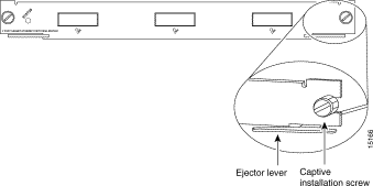
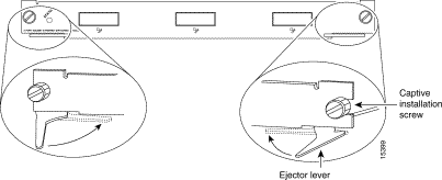
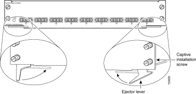
Step 2 Loosen the captive installation screws, as shown in Figure 4.
Step 3 Place your thumbs on the left and right ejector levers and simultaneously pull the levers outward to release the module from the backplane connector. Figure 4 shows a close-up of the right ejector lever.
Step 4 Grasp the switching module with one hand and place your other hand under the carrier to support and guide it out of the slot. Do not touch the printed circuit boards or connector pins.
Step 5 Carefully pull the switching module straight out of the slot, keeping one hand under the carrier to guide it.
Step 6 Place the switching module on an antistatic mat or antistatic foam, or immediately install it in another slot.
Step 7 If the slot is to remain empty, install a switching-module filler plate (part number 800-00292-01) to keep dust out of the chassis and to allow airflow through the switching-module compartment.
To install the Gigabit Ethernet switching module (WS-X5403) in a Catalyst 5000 series switch, perform these steps:
Step 2 Choose a slot for the new switching module. See Table 6 for restrictions. Ensure that you have enough clearance for any interface equipment that you will connect directly to the switching module ports. If possible, place switching modules between empty slots that contain only switching-module filler plates.
Step 3 Loosen the captive installation screws securing the switching-module filler plate (or the existing switching module) to the desired slot.
Step 4 Remove the switching-module filler plate (or the existing switching module). Save the switching-module filler plate for future use.
Note If you are removing an existing switching module, place one hand carefully under the carrier to support the switching module as you slide it out of the chassis. Place the removed module in an antistatic bag or on an antistatic surface.
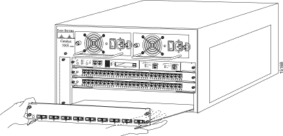
Step 5 To install the new module, hold the switching-module front panel with one hand, and place your other hand under the carrier to support the switching module. Do not touch the printed circuit boards or connector pins.
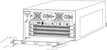
Step 6 Align the edges of the switching-module carrier with the slot guides on the sides of the switch chassis as shown in Figure 5.
Note Use the same procedure for all the Catalyst 5000 series switches.
Step 7 Pivot the two module ejector levers out away from the faceplate as shown in Figure 5.
Step 8 Carefully slide the switching module into the slot until the notches on both ejector levers engage the chassis sides.
Step 9 Using the thumb and forefinger of each hand, simultaneously pivot in both ejector levers, as shown in Figure 6, to fully seat the switching module in the backplane connector.
Note If you perform a hot swap, the console displays the message "Module n has been inserted." This message also appears if you are connected to the Catalyst 5000 series switch through a Telnet session.
Step 10 Use a screwdriver to tighten the captive installation screws on each end of the switching-module faceplate.
Step 11 If not already done, install the GBICs. See the "GBIC Handling Guidelines and Installation" section for details.
Note If you are connecting the 1000BaseLX/LH (WS-X5486) GBICs to an MMF network, you must install a mode-conditioning patch cord. See the "Mode-Conditioning Patch Cord" section for details.
Step 12 Attach network interface cables or other devices to the interface ports. See the "Connecting GBICs to the Gigabit Ethernet and Gigabit EtherChannel Ports" section for details.
Step 13 Check the status of the module. See the "Checking the Interface Status" section for details.
To install the Gigabit EtherChannel switching module (WS-X5410), perform these steps:
 |
Tip |
Because of the GEM's two-slot design, this module is more difficult to insert and remove than single-slot modules. Use care when inserting and removing the Gigabit EtherChannel switching module. Insertion and removal should be done in a single, smooth motion.
Step 2 Choose a slot for the new switching module. See Table 7 for restrictions. Ensure that you have enough clearance for any interface equipment that you will connect directly to the switching-module ports. If possible, place switching modules between empty slots that contain only switching-module filler plates.
Note The Gigabit EtherChannel switching module requires two empty slots.
Step 3 Loosen the captive installation screws securing the switching-module filler plates (or the existing switching modules) to the desired slots.
Step 4 Remove the switching-module filler plates (or the existing switching modules). Save the switching-module filler plates for future use.
Note If you are removing an existing switching module, see the "Removing Switching Modules" section.
Step 5 To install the new module, hold the switching-module front panel with one hand, and place your other hand under the carrier to support the switching module. Do not touch the printed circuit boards or connector pins.
Step 6 Align the edges of the switching-module carrier with the slot guides on the sides of the switch chassis, as shown in Figure 7.
Note Align the edges of the switching-module carrier with the slot guides in the lower of the two empty slots.
Step 7 Pivot the two module ejector levers out away from the faceplate as shown in Figure 7.
Step 8 Carefully slide the switching module into the slot until the notches on both ejector levers engage the chassis sides.
Step 9 Using the thumb and forefinger of each hand, simultaneously pivot in both ejector levers, as shown in Figure 8, to fully seat the switching module in the backplane connector.
Note If you perform a hot swap, the console displays the message "Module n has been inserted." This message also appears if you are connected to the Catalyst 5000 series switch through a Telnet session.
Step 10 Use a screwdriver to tighten the captive installation screws on the left and right sides of the module.
Step 11 If not already done, install the GBICs. See the "GBIC Handling Guidelines and Installation" section for details.
Note If you are connecting the 1000BaseLX/LH (WS-X5486) GBICs to an MMF network, you must install a mode-conditioning patch cord. See the "Mode-Conditioning Patch Cord" section for details.
Step 12 Attach network interface cables or other devices to the interface ports. See the "Connecting GBICs to the Gigabit Ethernet and Gigabit EtherChannel Ports" section for details.
Step 13 Check the status of the module. See the "Checking the Interface Status" section for details.
This section describes how to install, remove, and maintain GBICs.
Follow these GBIC handling guidelines:
To install a GBIC, perform these steps:
Step 2 Verify that the GBIC is the correct type for your network by checking the part number. The number indicates whether it is 1000BaseSX, 1000BaseLX/LH, or 1000BaseZX.
Note Three GBIC styles are available: WS-G5484 (1000BaseSX), WS-G5486 (1000BaseLX/LH), and WS-G5487 (1000BaseZX).
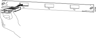
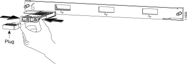
Step 3 Grip the sides of the GBIC with your thumb and forefinger; insert the GBIC into the slot on the front of the Gigabit Ethernet or Gigabit EtherChannel switching module (see Figure 9). GBICs are keyed to prevent incorrect insertion.
Note A maximum of 6 1000BaseZX GBICs are supported in a switch chassis.
Step 4 Slide the GBIC through the flap covering the slot opening. Continue sliding the GBIC into the slot until you hear a click. The click indicates that the GBIC is locked in the slot.
Step 5 When you are ready to attach the fiber-optic cable, remove the plugs from the GBIC. Save the plug for future use.
Note If you are connecting the 1000BaseLX/LH (WS-X5486) GBICs to an MMF network, you must install a mode-conditioning patch cord. See the "Mode-Conditioning Patch Cord" section for details.
To connect GBICs to the Gigabit Ethernet or Gigabit EtherChannel ports, perform these steps:
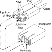
Step 2 Remove the plugs from the SC connector (see Figure 10) on the fiber-optic cable. Insert the connector into the GBIC.
Note When you plug the SC connector into the GBIC, make sure that both the tx (transmit) and rx (receive) fiber-optic cables are fully inserted into the SC connector.
Note If you are using the LX/LH GBIC with MMF, you need to install a patch cord between the GBIC and the MMF cable. See the "Mode-Conditioning Patch Cord" section for details.
To remove a GBIC, perform these steps:
Step 2 Release the GBIC from the slot by simultaneously squeezing the plastic tabs (see Figure 11).
Step 3 Slide the GBIC out of the slot.
Step 4 Install the plugs in the GBIC optical bores, and place the GBIC in protective packaging.
When using the 1000BaseLX/LH GBIC with 62.5-micron diameter MMF, you must install a mode-conditioning patch cord (Cisco product number CAB-GELX-625 or equivalent) between the GBIC and the MMF cable on both the transmit and receive ends of the link. The patch cord is required for link distances greater than 984 feet (300 meters).
Note For link spans of less than 300 meters, the patch cord can be omitted; however, using the LX/LH GBIC with MMF and no patch cord for very short link distances (tens of meters) is not recommended. The result could be an elevated bit error rate (BER).
Note The patch cord is required to comply with IEEE standards. The IEEE found that link distances could not be met with certain types of fiber-optic cable due to a problem in the center of some fiber-optic cable cores. The solution is to launch light from the laser at a precise offset from the center by using the patch cord. At the output of the patch cord, the LX/LH GBIC is compliant with the IEEE 802.3z standard for 1000BaseLX. For a detailed description of this problem, refer to Appendix C, "Differential Mode Delay," in the Catalyst 5000 Series Supervisor Engine Installation Guide.
Note Cisco Gigabit Ethernet products have been tested and evaluated to comply with the standards listed in the "Standards Compliance" section. Equivalent cables should also meet these standards.
Figure 12 shows a typical configuration using the patch cord.
Plug the end of the patch cord labeled "To Equipment" into the GBIC (see Figure 13). Plug the end labeled "To Cable Plant" into the patch panel. The patch cord is 9.84 feet (3 meters) long and has duplex SC-male connectors at each end.
Check the status of the interfaces as follows:
This section lists the default configurations of the Gigabit Ethernet and Gigabit EtherChannel switching modules and the commands you can use to customize your configuration.
The features you can customize have default values that are likely to suit your environment and need not be changed. Table 8 lists the default values of these features.
| Feature | Default Setting |
|---|---|
| 1Port availability for the Gigabit Ethernet module depends on which Catalyst 5000 series switch the module is installed in and in which slot the module is installed.
2Gigabit Ethernet module ports can operate only in full duplex. 3Gigabit EtherChannel is not supported on the WS-X5403. |
Table 9 lists the tasks and commands to configure the Gigabit Ethernet and Gigabit EtherChannel module ports.
| Task | Command |
|---|---|
| Setting Up the System | |
| Checking Connectivity | |
The Gigabit Ethernet switching modules use flow control, which inhibits packet transmission to the Gigabit Ethernet module for a period of time. If the Gigabit Ethernet switching module's receive buffer becomes full, the module transmits a "pause" packet that tells remote devices to delay sending more packets for a specified period of time. The Gigabit Ethernet switching module can also receive "pause" packets from other devices.
To configure flow control, enter the set port flowcontrol {receive | send} mod_num/port_num {off | on | desired} command. Table 10 lists the flow-control tasks and commands.
This example shows how to turn on transmit flow control:
This example shows how to set transmit flow control to advertise that it will send flow-control frames if the attached device elects to receive them:
This example shows how to turn off transmit flow control:
This example shows how to turn on receive flow control:
This example shows how to set receive flow control to advertise that it will accept flow-control frames if the attached device elects to transmit them:
This example shows how to turn off receive flow control:
To display the current flow-control status and statistics, perform this task:
This example shows how to verify the flow-control configuration:
Table 11 shows output field descriptions for the show port flowcontrol command:
Ports can be characterized by their ability to generate and respond to flow control frames (pause frames) as well as the pause behavior they require of their link partner.
The Gigabit EtherChannel module's Gigabit Ethernet ports respond to received pause frames. Upon configuration, these ports advertise a pause capability. The ports at the two ends of the link negotiate a mutually acceptable flow-control configuration.
A pause frame is never generated by the Gigabit EtherChannel module's Gigabit Ethernet ports.
In all cases, pause frames received on the module are processed internally and are not switched through the system.
To configure flow-control, enter the set port flowcontrol {receive | send} [mod_num/port_num] {off | on | desired} command. Table 12 lists the flow-control tasks and commands.
| Task | Command |
|---|---|
Causes the local port to advertise that it will send flow-control frames1. |
|
Causes the local port to advertise that it will send flow-control frames if the attached device elects to receive them1 (default). |
|
Turns off a local port's ability to send flow-control packets to a remote device. |
|
Requires a local port to be flow controlled by a remote device. |
|
Causes the local port to operate with an attached device that is required to send flow-control packets or with an attached device that is not required to but may send flow-control packets. |
|
Turns off an attached device's ability to send flow-control packets to a local port (default). |
| 1Even though the GEM never sends flow-control frames, this configuration option is useful if the attached device refuses to complete negotiation unless the local device advertises that it will send flow-control frames. For cases where the attached device is willing to accept flow-control frames, there is no adverse effect in advertising to that attached device that the local device intends to send them. |
This example shows how to turn transmit flow control on:
This example shows how to set transmit flow control to advertise that it will send flow-control frames if the attached device elects to receive them:
This example shows how to turn transmit flow control off:
This example shows how to turn receive flow control on:
This example shows how to set receive flow control to advertise that it will accept flow-control frames if the attached device elects to transmit them:
This example shows how to turn off receive flow control:
To display the current flow-control status and statistics, perform this task:
This example shows how to verify the flow-control configuration:
Table 13 shows the Output field descriptions for the show port flowcontrol command.
Unlike 10/100 Fast Ethernet ports, autonegotiation with Gigabit Ethernet does not involve negotiating port speed. You cannot disable autonegotiation on Gigabit Ethernet ports by setting the port speed and duplex state. With Gigabit Ethernet, the link negotiation protocol is used to exchange flow-control behavior, remote fault information, and duplex information (even though the Catalyst 5000 series gigabit ports only support full-duplex operation). In Gigabit Ethernet, you can control whether the link negotiation protocol runs with the set port negotiation command.
Table 14 shows the four possible autonegotiation configurations for a link and the resulting link status for each configuration.
| Autonegotiation State | Link Status | ||
| Near End1 | Far End2 | Near End | Far End |
| 1Refers to the GEM's front panel port.
2Refers to the remote port at the other end of the gigabit link. |
Both ends of the link must have the same setting. The link will not come up if the two ends of the link are set inconsistently (link negotiation enabled on one end and disabled on the other).
The link negotiation protocol is enabled by default. To enable or disable the link negotiation protocol on a port, perform this task:
| Task | Command |
|---|---|
This example shows how to turn link negotiation off:
To display the link negotiation protocol setting for the specified port, perform this task:
| Task | Command |
|---|---|
This example shows how to verify the link negotiation configuration:
This equipment has been tested and found to comply with the limits for a Class A digital device, pursuant to part 15 of the FCC rules. These limits are designed to provide reasonable protection against harmful interference when the equipment is operated in a commercial environment. This equipment generates, uses, and can radiate radio-frequency energy and, if not installed and used in accordance with the instruction manual, may cause harmful interference to radio communications. Operation of this equipment in a residential area is likely to cause harmful interference, in which case users will be required to correct the interference at their own expense.
You can determine whether your equipment is causing interference by turning it off. If the interference stops, it was probably caused by the Cisco equipment or one of its peripheral devices. If the equipment causes interference to radio or television reception, try to correct the interference by using one or more of the following measures:
Modifications to this product not authorized by Cisco Systems could void the FCC approval and negate your authority to operate the product.
Cisco Connection Online (CCO) is Cisco Systems' primary, real-time support channel. Maintenance customers and partners can self-register on CCO to obtain additional information and services.
Available 24 hours a day, 7 days a week, CCO provides a wealth of standard and value-added services to Cisco's customers and business partners. CCO services include product information, product documentation, software updates, release notes, technical tips, the Bug Navigator, configuration notes, brochures, descriptions of service offerings, and download access to public and authorized files.
CCO serves a wide variety of users through two interfaces that are updated and enhanced simultaneously: a character-based version and a multimedia version that resides on the World Wide Web (WWW). The character-based CCO supports Zmodem, Kermit, Xmodem, FTP, and Internet e-mail, and it is excellent for quick access to information over lower bandwidths. The WWW version of CCO provides richly formatted documents with photographs, figures, graphics, and video, as well as hyperlinks to related information.
You can access CCO in the following ways:
For a copy of CCO's Frequently Asked Questions (FAQ), contact cco-help@cisco.com. For additional information, contact cco-team@cisco.com.
Note If you are a network administrator and need personal technical assistance with a Cisco product that is under warranty or covered by a maintenance contract, contact Cisco's Technical Assistance Center (TAC) at 800 553-2447, 408 526-7209, or tac@cisco.com. To obtain general information about Cisco Systems, Cisco products, or upgrades, contact 800 553-6387, 408 526-7208, or cs-rep@cisco.com.
Cisco documentation and additional literature are available in a CD-ROM package, which ships with your product. The Documentation CD-ROM, a member of the Cisco Connection Family, is updated monthly. Therefore, it might be more current than printed documentation. To order additional copies of the Documentation CD-ROM, contact your local sales representative or call customer service. The CD-ROM package is available as a single package or as an annual subscription. You can also access Cisco documentation on the World Wide Web at http://www.cisco.com, http://www-china.cisco.com, or http://www-europe.cisco.com.
If you are reading Cisco product documentation on the World Wide Web, you can submit comments electronically. Click Feedback in the toolbar and select Documentation. After you complete the form, click Submit to send it to Cisco. We appreciate your comments.
![]()
![]()
![]()
![]()
![]()
![]()
![]()
![]()
Posted: Sat Jan 18 14:54:30 PST 2003
All contents are Copyright © 1992--2002 Cisco Systems, Inc. All rights reserved.
Important Notices and Privacy Statement.