cc/td/doc/product/lan/cat4000
hometocprevnextglossaryfeedbacksearchhelp
PDF

Table Of Contents

Installation and Configuration Note for the Catalyst 4000 Family Supervisor Engine IV

Contents

Safety Overview

Supervisor Engine IV

Features of the Supervisor Engine Front Panel

Port Cabling Specifications

Maximum Cable Distances

Using a Patch Cord

Installing and Removing the Supervisor Engine

Required Tools

Installing the Supervisor Engine

Removing the Supervisor Engine

Attaching Module Interface Cables

Configuring Your Supervisor Engine

GBIC Handling Guidelines and Installation

Installing a GBIC

Removing a GBIC

GBIC Maintenance Guidelines

Standards Compliance Specifications

Related Documentation

Obtaining Documentation

World Wide Web

Documentation CD-ROM

Ordering Documentation

Documentation Feedback

Obtaining Technical Assistance

Cisco.com

Technical Assistance Center


Installation and Configuration Note for the Catalyst 4000 Family Supervisor Engine IV


Product Numbers: WS-X4515 = Catalyst 4000 Family Supervisor Engine IV

This publication describes how to install and verify the operation of the Catalyst 4000 family Supervisor Engine IV. Refer to the software configuration guide for your switch for configuration information for the supervisor engines and switching modules.

Contents

This document contains these sections:

Safety Overview

Supervisor Engine IV

Port Cabling Specifications

Installing and Removing the Supervisor Engine

Attaching Module Interface Cables

Configuring Your Supervisor Engine

GBIC Handling Guidelines and Installation

Standards Compliance Specifications

Related Documentation

Obtaining Documentation

Obtaining Technical Assistance

Safety Overview

Throughout this publication, safety warnings appear in procedures that may harm you if performed incorrectly. A warning symbol precedes each warning statement.

Warning This warning symbol means danger. You are in a situation that could cause bodily injury. Before you work on any equipment, be aware of the hazards involved with electrical circuitry and be familiar with standard practices for preventing accidents. To see translations of the warnings that appear in this publication, refer to the Regulatory Compliance and Safety Information document that accompanied this device.

Waarschuwing

Dit waarschuwingssymbool betekent gevaar. U verkeert in een situatie die lichamelijk letsel kan veroorzaken. Voordat u aan enige apparatuur gaat werken, dient u zich bewust te zijn van de bij elektrische schakelingen betrokken risico's en dient u op de hoogte te zijn van standaard maatregelen om ongelukken te voorkomen. Voor vertalingen van de waarschuwingen die in deze publicatie verschijnen, kunt u het document Regulatory Compliance and Safety Information (Informatie over naleving van veiligheids- en andere voorschriften) raadplegen dat bij dit toestel is ingesloten.

Varoitus

Tämä varoitusmerkki merkitsee vaaraa. Olet tilanteessa, joka voi johtaa ruumiinvammaan. Ennen kuin työskentelet minkään laitteiston parissa, ota selvää sähkökytkentöihin liittyvistä vaaroista ja tavanomaisista onnettomuuksien ehkäisykeinoista. Tässä julkaisussa esiintyvien varoitusten käännökset löydät laitteen mukana olevasta Regulatory Compliance and Safety Information -kirjasesta (määräysten noudattaminen ja tietoa turvallisuudesta).

Attention

Ce symbole d'avertissement indique un danger. Vous vous trouvez dans une situation pouvant causer des blessures ou des dommages corporels. Avant de travailler sur un équipement, soyez conscient des dangers posés par les circuits électriques et familiarisez-vous avec les procédures couramment utilisées pour éviter les accidents. Pour prendre connaissance des traductions d'avertissements figurant dans cette publication, consultez le document Regulatory Compliance and Safety Information (Conformité aux rčglements et consignes de sécurité) qui accompagne cet appareil.

Warnung

Dieses Warnsymbol bedeutet Gefahr. Sie befinden sich in einer Situation, die zu einer Körperverletzung führen könnte. Bevor Sie mit der Arbeit an irgendeinem Gerät beginnen, seien Sie sich der mit elektrischen Stromkreisen verbundenen Gefahren und der Standardpraktiken zur Vermeidung von Unfällen bewußt. Übersetzungen der in dieser Veröffentlichung enthaltenen Warnhinweise finden Sie im Dokument Regulatory Compliance and Safety Information (Informationen zu behördlichen Vorschriften und Sicherheit), das zusammen mit diesem Gerät geliefert wurde.

Avvertenza

Questo simbolo di avvertenza indica un pericolo. La situazione potrebbe causare infortuni alle persone. Prima di lavorare su qualsiasi apparecchiatura, occorre conoscere i pericoli relativi ai circuiti elettrici ed essere al corrente delle pratiche standard per la prevenzione di incidenti. La traduzione delle avvertenze riportate in questa pubblicazione si trova nel documento Regulatory Compliance and Safety Information (Conformitā alle norme e informazioni sulla sicurezza) che accompagna questo dispositivo.

Advarsel

Dette varselsymbolet betyr fare. Du befinner deg i en situasjon som kan føre til personskade. Før du utfører arbeid på utstyr, må du vare oppmerksom på de faremomentene som elektriske kretser innebærer, samt gjøre deg kjent med vanlig praksis når det gjelder å unngå ulykker. Hvis du vil se oversettelser av de advarslene som finnes i denne publikasjonen, kan du se i dokumentet Regulatory Compliance and Safety Information (Overholdelse av forskrifter og sikkerhetsinformasjon) som ble levert med denne enheten.

Aviso

Este símbolo de aviso indica perigo. Encontra-se numa situaįão que lhe poderá causar danos físicos. Antes de comeįar a trabalhar com qualquer equipamento, familiarize-se com os perigos relacionados com circuitos eléctricos, e com quaisquer práticas comuns que possam prevenir possíveis acidentes. Para ver as traduįões dos avisos que constam desta publicaįão, consulte o documento Regulatory Compliance and Safety Information (Informaįão de Seguranįa e Disposiįões Reguladoras) que acompanha este dispositivo.

ĄAdvertencia!

Este símbolo de aviso significa peligro. Existe riesgo para su integridad física. Antes de manipular cualquier equipo, considerar los riesgos que entraņa la corriente eléctrica y familiarizarse con los procedimientos estándar de prevenciķn de accidentes. Para ver una traducciķn de las advertencias que aparecen en esta publicaciķn, consultar el documento titulado Regulatory Compliance and Safety Information (Informaciķn sobre seguridad y conformidad con las disposiciones reglamentarias) que se acompaņa con este dispositivo.

Varning!

Denna varningssymbol signalerar fara. Du befinner dig i en situation som kan leda till personskada. Innan du utför arbete på någon utrustning måste du vara medveten om farorna med elkretsar och känna till vanligt förfarande för att förebygga skador. Se förklaringar av de varningar som förkommer i denna publikation i dokumentet Regulatory Compliance and Safety Information (Efterrättelse av föreskrifter och säkerhetsinformation), vilket medföljer denna anordning.


Supervisor Engine IV

This section describes the Catalyst 4000 family Supervisor Engine IV (WS-X4515). This supervisor engine provides data path and data control for all network interfaces.

The Supervisor Engine IV is supported by the Catalyst 4006, 4503, 4506, and 4507R switches. Install the Supervisor Engine IV in slot 1 of all Catalyst 4000 family switches. You can install two Supervisor Engine IVs in a Catalyst 4507R switch with the second supervisor engine serving as a redundant supervisor engine. The Supervisor Engine IV in slot 1 of the Catalyst 4507R switch is the primary supervisor engine. The Supervisor Engine IV in slot 2 of the Catalyst 4507R switch is the redundant supervisor engine.

The supervisor engine is hot swappable, but packets are not forwarded when the supervisor engine has been removed. When a supervisor engine is reinserted, the system reboots.

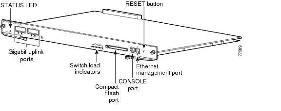
Figure 1 Catalyst 4000 Family Supervisor Engine IV (WS-X4515)

The supervisor engine includes interfaces for SNMP, console, and Telnet, and provides management functions, such as environmental status monitoring.

Features of the Supervisor Engine Front Panel

The following sections describe the LEDs, connectors, and switches on the Catalyst 4000 family Supervisor Engine IV:

LEDs

Gigabit Ethernet Uplink Ports

Ethernet Management Port

Console Port

Reset Button

Flash Port

LEDs

Table 1 describes the LEDs on the supervisor engine front panel .

Table 1 Supervisor Engine LEDs (WS-X4515) 

LED
LED Status
Description

STATUS


Indicates the results of a series of self-tests.


Green

All diagnostic tests passed.


Red

A test failed.


Orange

System boot or diagnostic test is in progress.


Off

Module is disabled.

UTILIZATION

Green 1-100%

If the switch is operational, this display indicates the current traffic load over the backplane (as an approximate percentage).

Link


Indicates the status of the 10/100BASE-T Ethernet management port or uplink ports.


Green

The link is operational.


Orange

The link is disabled by user.


Flashing orange

The power-on self-test indicates a faulty port.


Off

No signal is detected or there is a link configuration failure.

Active


Indicates whether the uplink port is active.


Green

The port is active.


Off

The port is not active.

ACTIVE


The LED to the right of the uplink ports is only used in switches with two supervisors to identify the active supervisor.


Gigabit Ethernet Uplink Ports

The Gigabit Ethernet uplink ports operate in full-duplex mode only. These ports use the 1000BASE-SX, 1000BASE-LX/LH, and 1000BASE-ZX Gigabit Interface Converters (GBICs). GBICs have SC connectors to interface with multimode fiber (MMF) and single-mode fiber (SMF) cable. For further information on GBICs, see the "GBIC Handling Guidelines and Installation" section.

Ethernet Management Port

The Ethernet management port is used (in ROMMON mode only) to recover a switch software image that has been corrupted or destroyed due to a network catastrophe. This port is not active while the switch is operating normally.

Console Port

The Catalyst 4000 family Supervisor Engine IV console port has an EIA/TIA-232 RJ-45 connector. The console port allows you to perform the following functions:

Configure the switch from the CLI

Monitor network statistics and errors

Configure SNMP agent parameters


Note EIA/TIA-232 was known as recommended standard RS-232 before its acceptance as a standard by the Electronic Industries Alliance (EIA) and Telecommunications Industry Association (TIA).


Reset Button

The Reset button is used to restart the switch.


Note Use a paper clip or other small, pointed object to press the Reset button.


Flash Port

The Flash port accepts a Type 1 compact Flash card. You can use it for file transfer tasks such as loading a new software image. The Flash card (MEM-C4K-FLD64M= or MEM-C4K-FLD128M=) is optional.

For more information, refer to Using the Compact Flash on the Catalyst 4000 Family Supervisor Engine III and IV at the following URL:

http://www.cisco.com/univercd/cc/td/doc/product/lan/cat4000/inst_nts/ol_2058.htm

Port Cabling Specifications

This section provides port cabling specifications and includes the following subsections:

Maximum Cable Distances

Using a Patch Cord

The length of your networks and the distances between connections depend on the type of signal, the signal speed, and the transmission medium (the type of cabling used to transmit the signals). The distance and rate limits in this document are the IEEE-recommended maximum speeds and distances for signaling. Table 2 shows the transmission speed versus the distance.

Table 2 EIA/TIA-232 Transmission Speed in Contrast with Distance 

Rate (bps)
Distance (ft)
Distance (m)

2400

200

60

4800

100

30

9600

50

15

19,200

25

7.6

38,400

12

3.7

56,000

8.6

2.6


Maximum Cable Distances

Table 3 shows the maximum cable distances for transceiver speed and cable type.

Table 3 Maximum Cable Distances 

Transceiver Speed
Cable Type
Duplex Mode
Maximum Distance Between Stations

10 Mbps

Category 3 UTP

Half or full

328 ft (100 m)

10 Mbps

MMF

Half or full

1.2 mi (2 km)

100 Mbps

Category 5 UTP

Half or full

328 ft (100 m)

100 Mbps

MMF

Half

1312 ft (400 m)

100 Mbps

MMF

Full

1.2 mi (2 km)


Table 4 provides cabling specifications for the GBICs that you install in the Gigabit Ethernet port modules. All GBIC ports have SC-type connectors, and the minimum cable distance for all GBICs listed is 6.5 feet (2 meters).

Table 4 GBIC Port Cabling Specifications 

GBIC
Wavelength (nm)
Fiber Type
Core Size (micron)
Modal Bandwidth
(MHz/km)
Cable Distance

SX1

850

MMF

62.5

160

722 ft (220 m)


62.5

200

902 ft (275 m)


50.0

400

1640 ft (500 m)


50.0

500

1804 ft (550 m)

LX/LH

1300

MMF2

62.5

500

1804 ft (550 m)


50.0

400

1804 ft (550 m)


50.0

500

1804 ft (550 m)


SMF

9/10

-

6.2 mi (10 km)

ZX

1550

SMF

9/10

-

43.5 mi (70 km)


SMF3

9/10


62.1 mi (100 km)

1 MMF only.

2 Patch cord required (see the "Using a Patch Cord" section for details).

3 Dispersion-shifted single-mode fiber-optic.


Using a Patch Cord

When using the LX/LH GBIC with 62.5-micron diameter MMF, you must install a mode-conditioning patch cord (Cisco product number CAB-GELX-625 or equivalent) between the GBIC and the MMF cable on both the transmit and receive ends of the link.

The patch cord is required for link distances greater than 984 feet (300 meters) and must comply with IEEE standards. The IEEE found that link distances could not be met with certain types of fiber-optic cable due to a problem in the center of some fiber-optic cable cores. The solution is to launch light from the laser at a precise offset from the center by using the patch cord. At the output of the patch cord, the LX/LH GBIC is compliant with the IEEE 802.3z standard for 1000BASE-LX. For a detailed description of this problem, refer to the installation guide for your switch.


Note We do not recommend using the LX/LH GBIC with MMF without a patch cord for very short link distances (tens of meters) either. The result could be an elevated bit error rate (BER).


Cisco Gigabit Ethernet products have been tested and evaluated to comply with the standards listed in Appendix A, "Specifications," of the installation guide for your switch. All equivalent cables should also meet these standards.

Installing and Removing the Supervisor Engine

All Catalyst 4000 family switches support hot swapping, which lets you install, remove, replace, and rearrange supervisor engines and switching modules without powering the system off. When the system detects that a switching module has been installed or removed, it runs diagnostic and discovery routines automatically, acknowledges the presence or absence of the module, and resumes system operation with no operator intervention.

This section contains the following subsections:

Required Tools

Installing the Supervisor Engine

Removing the Supervisor Engine

Required Tools

You will need these tools to install a supervisor engine in a Catalyst 4000 family switch:

Number 1 and number 2 Phillips screwdrivers for the captive installation screws on most modules

3/16-inch flat-blade screwdriver for the captive installation screws on other modules

Antistatic mat or antistatic foam

Wrist strap or other grounding device


Note Whenever you handle supervisor engines, use a wrist strap or other grounding device to prevent ESD damage.


Installing the Supervisor Engine

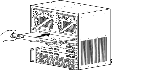
Catalyst 4000 family switches have horizontal chassis slots that are numbered from top to bottom. On the Catalyst 4006, 4503, and 4506 switches, you can only install the supervisor engine in slot 1. On the Catalyst 4507R switch, you install the primary supervisor engine in slot 1. You can install an optional redundant supervisor engine in slot 2.


Warning During this procedure, wear grounding wrist straps to avoid ESD damage to the card. Do not directly touch the backplane with your hand or any metal tool, or you could shock yourself.


Caution To prevent ESD damage, handle supervisor engines by the carrier edges only.

To install a supervisor engine in a Catalyst 4000 family switch, follow this procedure:


Step 1 Take the necessary precautions to prevent ESD damage as described in the Site Preparation and Safety Guide.

Step 2 Ensure that you have enough clearance to accommodate any interface equipment that you will connect directly to the supervisor engine ports.

Step 3 Loosen the captive installation screws that secure the switching-module filler plate or the existing supervisor engine (whichever is present) and remove it.

Step 4 Remove the supervisor engine filler plate or the existing supervisor engine from slot 1. If a switching module filler plate was installed, save it for future use. If you are removing an existing supervisor engine, see the "Removing the Supervisor Engine" section.

Step 5 To install the new supervisor engine, grasp the switching module front panel with one hand and place your other hand under the carrier to support the supervisor engine, as shown in Figure 2. Do not touch the printed circuit boards or connector pins.

Step 6 Align the edges of the supervisor engine carrier with the slot guides on the sides of the switch chassis, as shown in Figure 2.

Figure 2 Installing the Supervisor Engine in the Chassis

Step 7 Pivot the two module ejector levers out and away from the faceplate.

Step 8 Carefully slide the supervisor engine into the slot until the notches on both ejector levers engage the chassis sides.

Step 9 Using the thumb and forefinger of each hand, simultaneously pivot in both ejector levers to fully seat the supervisor engine in the backplane connector.


Caution Always use the ejector levers when installing or removing a supervisor engine. A supervisor engine that is partially seated in the backplane will not function correctly.

Step 10 Use a screwdriver to tighten the captive installation screws on each end of the supervisor engine faceplate.


To check the status of the module, perform these steps:


Step 1 Ensure that the LED labeled Status is green (module operational).

Step 2 When the switch is online, enter the show module command. Verify that the system acknowledges the new module and that the module's status is good.

Step 3 If the module is not operational, reseat it. If the module is still not operational, contact your customer service representative.


Removing the Supervisor Engine


Warning Because invisible radiation may be emitted from the aperture of the port when no fiber cable is connected, avoid exposure to radiation and do not stare into open apertures.


Warning During this procedure, wear grounding wrist straps to avoid ESD damage to the card. Do not directly touch the backplane with your hand or any metal tool, or you could shock yourself.


Caution To prevent ESD damage, handle supervisor engines by the carrier edges only.

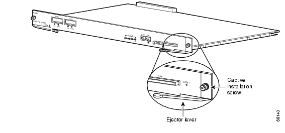
To remove a supervisor engine from a Catalyst 4000 family switch, follow this procedure:


Step 1 Disconnect any network interface cables attached to the ports on the supervisor engine that you intend to remove.

Step 2 Loosen the captive installation screws (see Figure 3).

Figure 3 Captive Installation Screws and Ejector Levers

Step 3 Grasp the left and right ejector levers and simultaneously pivot the levers outward to release the supervisor engine from the backplane connector. Figure 3 shows a close-up of the right ejector lever.

Step 4 Grasp the front panel of the supervisor engine with one hand and place your other hand under the carrier to support and guide it out of the slot. Do not touch the printed circuit boards or connector pins.

Step 5 Carefully pull the supervisor engine straight out of the slot, keeping your other hand under the carrier to guide it.

Step 6 Place the supervisor engine on an antistatic mat or antistatic foam, or immediately install it in another slot.


Warning Blank faceplates and cover panels serve three important functions: they prevent exposure to hazardous voltages and currents inside the chassis; they contain electromagnetic interference (EMI) that might disrupt other equipment; and they direct the flow of cooling air through the chassis. Do not operate the system unless all cards, faceplates, front covers, and rear covers are in place.


Step 7 If the slot is to remain empty, install a switching-module filler plate (part number 800-00292-01).


Attaching Module Interface Cables

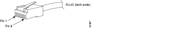
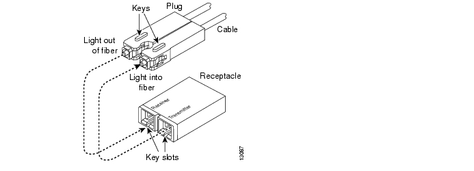
Figure 4 and Figure 5 show the connector types used to attach interface cables to the supervisor engine.

Figure 4 RJ-45 Connector


Note Always keep caps and plugs on the fiber-optic connectors on the cable and the switch when they are not in use.


Warning Because invisible radiation may be emitted from the aperture of the port when no fiber cable is connected, avoid exposure to radiation and do not stare into open apertures.


Figure 5 SC-Type Fiber-Optic Connector

Configuring Your Supervisor Engine

For information and commands to configure your supervisor engine, refer to the Software Configuration Guide for your switch.

GBIC Handling Guidelines and Installation

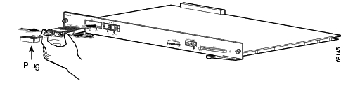
A GBIC (see Figure 6) is a hot swappable input/output device that plugs into the Gigabit Ethernet port of a supervisor engine and links the supervisor engine with a fiber-optic network. GBICs are online swappable.

Figure 6 Gigabit Interface Converter

The following GBIC media types are supported:

1000BASE-SX (WS-G5484)

1000BASE-LX/LH (WS-G5486)

1000BASE-ZX (WS-G5487)


Caution Because of interoperability issues, Cisco does not support GBICs purchased from third-party vendors.

Cisco 1000BASE-LX/LH interfaces fully comply with the IEEE 802.3z 1000BASE-LX standard. However, their higher optical quality allows them to reach 10 km over SMF cable instead of the 5 km specified in the standard.

If an LX/LH GBIC designed for operation on an SMF cable is directly coupled to an MMF cable, an effect known as Differential Mode Delay (DMD) might occur. See the Catalyst 4000 Family Module Installation Guide for more information.

This section describes the following topics:

Installing a GBIC

Removing a GBIC

GBIC Maintenance Guidelines

Installing a GBIC

A supervisor engine can be shipped with or without GBICs installed.


Caution When removing or inserting a GBIC, always wear an ESD wrist strap connected to the ESD wrist strap connector.


Caution Unnecessary removal or insertion of a GBIC can lead to premature failure of the GBIC. A GBIC has a lifetime of 100 to 500 removals and insertions.


Note This product has been evaluated to and complies with acceptable-safety-emission limits for Class 1 lasers. However, you should still take general precautions when working with lasers.


Warning Because invisible radiation may be emitted from the aperture of the port when no fiber cable is connected, avoid exposure to radiation and do not stare into open apertures.


To install a GBIC, follow this procedure:


Step 1 Remove the GBIC from its protective packaging.

Step 2 Verify that the GBIC is the correct type for your network by checking the GBIC part number. The part number indicates whether it is 1000BASE-SX, 1000BASE-LX/LH, or 1000BASE-ZX.

Step 3 Grasp the sides of the GBIC with your thumb and forefinger; insert the GBIC into the desired slot on the front of the module (see Figure 7).


Note GBICs are keyed to prevent incorrect insertion into a slot.


Figure 7 Installing a GBIC

Step 4 Slide the GBIC into the slot until you hear a click. The click indicates that the GBIC is locked into the slot.

Step 5 When you are ready to attach the fiber-optic cable, remove the plug from the GBIC and save it for future use.


Caution Do not remove the plugs from the GBIC optical bores or the fiber-optic cable until you are ready to connect the cable. The plugs protect the GBIC optical bores and cable from contamination.

Step 6 Remove the plugs from the SC-type connector on the fiber-optic cable (see Figure 5 on page 13). Insert the connector into the GBIC.


Note When you plug the SC-type connector into the GBIC, ensure that you fully insert the Tx and Rx fiber-optic cables into the SC-type connector.


Note If you are using the LX/LH GBIC with MMF, you need to install a patch cord between the GBIC and the MMF cable. See the "Using a Patch Cord" section for details.


Removing a GBIC


Warning Because invisible radiation may be emitted from the aperture of the port when no fiber cable is connected, avoid exposure to radiation and do not stare into open apertures.


To remove a GBIC, follow this procedure:


Step 1 Disconnect the fiber-optic cable from the GBIC SC-type connector.

Step 2 Release the GBIC from the slot by simultaneously squeezing the plastic tabs (one on each side of the GBIC).

Step 3 Slide the GBIC out of the slot.

Step 4 Install the two plugs into the GBIC optical bores, and place the GBIC in its protective packaging.


GBIC Maintenance Guidelines

To properly maintain GBICs, follow these guidelines:

GBICs are sensitive to static. To prevent ESD damage, follow normal handling procedures.

GBICs are sensitive to dust. When the GBIC is stored or when a fiber-optic cable is not plugged in, always keep plugs in the optical bores.

The most common source of contaminants in the optical bores is debris picked up on the ferrules of the optical connectors. Use an alcohol swab or Kim-Wipe to clean the ferrules of the optical connector.

Standards Compliance Specifications

When installed in a system, the Catalyst 4000 family modules comply with the standards listed in Table 5:

Table 5 Standards Compliance Specifications

Item
Specification
Compliance

CE1 Marking

Safety

UL2 60950, CSA3 -C22.2 No. 60950, EN4 60950, IEC5 60950, TS0016 ,
AS/NZS7 3260

EMC8

FCC9 Part 15, Class A (CFR10 47) (USA), ICES11 -003 Class A (Canada), EN 55022 Class A (Europe), CISPR2212 Class A (International), AS/NZS 3548 Class A (Australia), and VCCI13 Class A (Japan) with UTP14

1 CE = European Compliance

2 UL = Underwriters Laboratory

3 CSA = Canadian Standards Association

4 EN = European Norm

5 IEC = International Electrotechnical Commission

6 TS = technical specifications

7 AS/NZS = Australia Standards/New Zealand Standards

8 EMC = electromagnetic compatibility

9 FCC = U.S. Federal Communications Commission

10 CFR = Code of Federal Regulations

11 ICES = Interference-Causing Equipment Standard

12 CISPR = Comite International Special des Perturbation Radioelectriques

13 VCCI = Voluntary Control Council for Information Technology Equipment

14 UTP = unshielded twisted-pair


The following modules have been found to comply with the limits for a Class A digital device per FCC (CFR 47) Part 15, ICES 003, EN55022, CISPR22, AS/NZS 3548, and VCCI with UTP cables, and complies with the limits for a Class B digital device per EN55022, CISPR22, AS/NZS 3548, and VCCI with shielded FTP cables with the following modules:

WS-X4012

WS-X4148-RJ21

WS-X4412-2GB-T

WS-X4013

WS-X4148-RJ45V

WS-X4418-GB

WS-X4014

WS-X4232-GB-RJ

WS-X4424-GB-RJ45

WS-X4019

WS-X4232-L3

WS-X4448-GB-LX

WS-X4124-FX-MT

WS-X4232-RJ-XX

WS-X4604-GWY

WS-X4148-FX-MT

WS-U4504-FX-MT


WS-X4148-RJ

WS-X4306-GB


Related Documentation

For more detailed installation and configuration information, refer to the following:

Site Preparation and Safety Guide

Catalyst 4000 Series Installation Guide

Catalyst 4500 Series Installation Guide

Catalyst 4000 Family Module Installation Guide

Regulatory Compliance and Safety Information for the Catalyst 4000 Family Switches

Software Configuration Guide—Catalyst 4000 Family, Catalyst 2948G, and Catalyst 2980G Switches

Command Reference—Catalyst 4000 Family, Catalyst 2948G, and Catalyst 2980G Switches

System Message Guide—Catalyst 6000 Family, Catalyst 5000 Family, Catalyst 4000 Family, Catalyst 2926G Series, Catalyst 2948G, and Catalyst 2980G Switches

Layer 3 Services Software Configuration Guide—Catalyst 5000 Family, Catalyst 4000 Family, Catalyst 2926G Series, Catalyst 2948G, and Catalyst 2980G Switches

Installation and Configuration Note for the Catalyst 4000 Family Supervisor Engine III

Obtaining Documentation

The following sections explain how to obtain documentation from Cisco Systems.

World Wide Web

You can access the most current Cisco documentation on the World Wide Web at the following URL:

http://www.cisco.com

Translated documentation is available at the following URL:

http://www.cisco.com/public/countries_languages.shtml

Documentation CD-ROM

Cisco documentation and additional literature are available in a Cisco Documentation CD-ROM package, which is shipped with your product. The Documentation CD-ROM is updated monthly and may be more current than printed documentation. The CD-ROM package is available as a single unit or through an annual subscription.

Ordering Documentation

Cisco documentation is available in the following ways:

Registered Cisco Direct Customers can order Cisco product documentation from the Networking Products MarketPlace:

http://www.cisco.com/cgi-bin/order/order_root.pl

Registered Cisco.com users can order the Documentation CD-ROM through the online Subscription Store:

http://www.cisco.com/go/subscription

Nonregistered Cisco.com users can order documentation through a local account representative by calling Cisco corporate headquarters (California, USA) at 408 526-7208 or, elsewhere in North America, by calling 800 553-NETS (6387).

Documentation Feedback

If you are reading Cisco product documentation on Cisco.com, you can submit technical comments electronically. Click Leave Feedback at the bottom of the Cisco Documentation home page. After you complete the form, print it out and fax it to Cisco at 408 527-0730.

You can e-mail your comments to bug-doc@cisco.com.

To submit your comments by mail, use the response card behind the front cover of your document, or write to the following address:

Cisco Systems
Attn: Document Resource Connection
170 West Tasman Drive
San Jose, CA 95134-9883

We appreciate your comments.

Obtaining Technical Assistance

Cisco provides Cisco.com as a starting point for all technical assistance. Customers and partners can obtain documentation, troubleshooting tips, and sample configurations from online tools by using the Cisco Technical Assistance Center (TAC) Web Site. Cisco.com registered users have complete access to the technical support resources on the Cisco TAC Web Site.

Cisco.com

Cisco.com is the foundation of a suite of interactive, networked services that provides immediate, open access to Cisco information, networking solutions, services, programs, and resources at any time, from anywhere in the world.

Cisco.com is a highly integrated Internet application and a powerful, easy-to-use tool that provides a broad range of features and services to help you to

Streamline business processes and improve productivity

Resolve technical issues with online support

Download and test software packages

Order Cisco learning materials and merchandise

Register for online skill assessment, training, and certification programs

You can self-register on Cisco.com to obtain customized information and service. To access Cisco.com, go to the following URL:

http://www.cisco.com

Technical Assistance Center

The Cisco TAC is available to all customers who need technical assistance with a Cisco product, technology, or solution. Two types of support are available through the Cisco TAC: the Cisco TAC Web Site and the Cisco TAC Escalation Center.

Inquiries to Cisco TAC are categorized according to the urgency of the issue:

Priority level 4 (P4)—You need information or assistance concerning Cisco product capabilities, product installation, or basic product configuration.

Priority level 3 (P3)—Your network performance is degraded. Network functionality is noticeably impaired, but most business operations continue.

Priority level 2 (P2)—Your production network is severely degraded, affecting significant aspects of business operations. No workaround is available.

Priority level 1 (P1)—Your production network is down, and a critical impact to business operations will occur if service is not restored quickly. No workaround is available.

Which Cisco TAC resource you choose is based on the priority of the problem and the conditions of service contracts, when applicable.

Cisco TAC Web Site

The Cisco TAC Web Site allows you to resolve P3 and P4 issues yourself, saving both cost and time. The site provides around-the-clock access to online tools, knowledge bases, and software. To access the Cisco TAC Web Site, go to the following URL:

http://www.cisco.com/tac

All customers, partners, and resellers who have a valid Cisco services contract have complete access to the technical support resources on the Cisco TAC Web Site. The Cisco TAC Web Site requires a Cisco.com login ID and password. If you have a valid service contract but do not have a login ID or password, go to the following URL to register:

http://www.cisco.com/register/

If you cannot resolve your technical issues by using the Cisco TAC Web Site, and you are a Cisco.com registered user, you can open a case online by using the TAC Case Open tool at the following URL:

http://www.cisco.com/tac/caseopen

If you have Internet access, it is recommended that you open P3 and P4 cases through the Cisco TAC Web Site.

Cisco TAC Escalation Center

The Cisco TAC Escalation Center addresses issues that are classified as priority level 1 or priority level 2; these classifications are assigned when severe network degradation significantly impacts business operations. When you contact the TAC Escalation Center with a P1 or P2 problem, a Cisco TAC engineer will automatically open a case.

To obtain a directory of toll-free Cisco TAC telephone numbers for your country, go to the following URL:

http://www.cisco.com/warp/public/687/Directory/DirTAC.shtml

Before calling, please check with your network operations center to determine the level of Cisco support services to which your company is entitled; for example, SMARTnet, SMARTnet Onsite, or Network Supported Accounts (NSA). In addition, please have available your service agreement number and your product serial number.


hometocprevnextglossaryfeedbacksearchhelp

Posted: Tue Apr 19 19:08:34 PDT 2005
All contents are Copyright © 1992--2005 Cisco Systems, Inc. All rights reserved.
Important Notices and Privacy Statement.