|
|

This chapter describes the safety instructions and site requirements needed for installing the Cisco ESSE and helps you prepare for installation. It contains the following major sections:
You need the following tools and equipment to install the Cisco ESSE:
This section provides safety information you will need when installing this product.
Read "Installing and Configuring the Cisco ESSE," before you connect the system to its power source. Failure to read and follow these guidelines could lead to an unsuccessful installation and possible damage to the system and components.
You should observe the following safety warnings when working with any equipment that connects to electrical power or telephone wiring. They can help you avoid injuring yourself and damaging the Cisco ESSE.
The following warnings and cautions are provided to help you prevent damage to the devices or injury to yourself:
 |
Warning Before working on a chassis or working near power supplies, unplug the power cord on AC units. |
|
Warning Before opening the chassis, disconnect the telephone-network cables to avoid contact with telephone-network voltages. |
|
Warning Only trained and qualified personnel should be allowed to install, replace, or service this equipment. |
|
Warning This equipment is intended to be grounded. Ensure that the host is connected to earth ground during normal use. |
|
Warning Do not work on the system or connect or disconnect cables during periods of lightning activity. |
|
Warning Ultimate disposal of this product should be handled according to all national laws and regulations. |
|
Warning Before working on a system that has an On/Off switch, turn OFF the power and unplug the power cord. |
|
Warning Read the installation instructions before you connect the system to its power source. |
|
Warning The device is designed to work with TN power systems. |
Observe the following general precautions when using and working with your system:
Follow these guidelines when working on equipment powered by electricity:
Static electricity can harm delicate components inside your computer. To prevent static damage, discharge static electricity from your body before you touch any of your computer's electronic components, such as the microprocessor. You can do so by touching an unpainted metal surface on the computer chassis.
As you continue to work inside the computer, periodically touch an unpainted metal surface to remove any static charge your body may have accumulated.
You can also take the following steps to prevent damage from electrostatic discharge (ESD):
When you run wires for any significant distance in an electromagnetic field, electromagnetic interference (EMI) can occur between the field and the signals on the wires.
Note the following:
To predict and remedy strong EMI, consult RFI experts.
This section describes the requirements your site must meet for safe installation and operation of your Cisco ESSE. Ensure that your site is properly prepared before beginning installation.
When planning your site layout and equipment locations, keep in mind the information provided in this section to help avoid equipment failures and reduce the possibility of environmentally caused shutdowns. If you are currently experiencing shutdowns or unusually high errors with your existing equipment, the precautions listed below will help you isolate the cause of failures and prevent future problems:
Follow these guidelines to create a safe operating environment:
|
Warning The plug-socket combination must be accessible at all times because it serves as the main disconnecting device. |
For Cisco ESSE power requirements, see "Technical Specifications."
Use the cables in the accessory kit to connect the Cisco ESSE console port to a console or computer that is running a console program. In addition to the console cable, you must supply your own standard Ethernet cable to connect the Cisco ESSE to your network. For information detailing cable requirements, see the "Network Cable Requirements" section.
A structured wiring system provides a standardized way to wire a building for all types of networks for the Cisco ESSE to be installed. The main distribution frame links all of the building's interior wiring and provides an interface connection to circuits coming from outside sources such as the local telephone company. Wiring hubs (peripherals for cabling installations) provide the connection logic unique to Fast Ethernet cables that the Cisco ESSE uses. Unshielded twisted pair (UTP) copper wire is used to connect the Cisco ESSE and distributes the network connections to wall jacks near each piece of network equipment.
Observe the following precautions for rack stability and safety. Also, refer to the rack installation documentation accompanying the rack for specific warning and/or caution statements and procedures.
 |
Note Servers, storage systems, and appliances are considered components in a rack. Thus, component refers to any server, storage system, or appliance, as well as to various peripherals or supporting hardware. |
| |||
|
| ||
Observe the following guidelines when working with options:
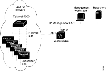
As part of the installation process, you must configure your Cisco ESSE. During this process, you are prompted to enter information for the two Ethernet interface ports. Ethernet 0 is used for IP communications, and Ethernet 1 is used for L2NMP management packet communications.
The IP interface is used for IP-based web-server-to-web-browser communications and can be physically isolated to a separate LAN, if you wish.
The L2NMP interface is used to exchange management packets with Cisco ONT 1031 devices located throughout the layer 2 network.
General notes on network configuration are provided in Table 2-1. An example of a Layer 2 network showing a Cisco ESSE is shown in Figure 2-1.
| Device Type | Tasks |
|---|---|
All |
Optional:
|
Catalyst 4000 switches |
|
The Cisco ESSE to Cisco ONT 1031 network switching fabric for the L2NMP interface is based on communicating at the Layer 2 level. The network switching fabric may either be configured on a single VLAN or as IEEE 802.1q trunks with appropriate VLANs.
If the network switching fabric is configured as a single VLAN, L2NMP management traffic and the Cisco ONT 1031 subscriber traffic will share this single VLAN. The Cisco ESSE L2NMP interface, for L2NMP management packet exchange, can potentially become overloaded due to excessive packet processing of the additional end user traffic or other high traffic source or surge (i.e., flooding or, potentially, the end user data) causing disruption of L2NMP management packet exchange. When the high traffic recedes, L2NMP packet communication resumes.
To avoid this potential issue, logically separate these two traffic streams by implementing the appropriate IEEE 802.1q trunk and VLAN configurations across your network.
L2NMP packets generated by Cisco ONT 1031 devices are without VLAN tags and will be placed onto the native VLAN (as required by IEEE 802.1q). Therefore, if you are distributing Cisco ONT 1031s across multiple VLANS in your network, each Cisco ONT 1031 network access port must be defined as a trunk and must contain the appropriate native VLAN and the second non-native VLAN for end user traffic. If you clear all other unnecessary VLANs from this trunk definition, traffic on this trunk will be kept to a minimum.
The network access port on the Cisco ESSE L2NMP interface therefore must also be defined as a trunk and contain all native VLANs from all Cisco ONT 1031 network access port trunk definitions. To prevent excess packet processing on the Cisco ESSE L2NMP interface, clear all extraneous VLANs from this trunk.
If all Cisco ONT 1031 access ports in the network are in the same native VLAN, the L2NMP interface's access port needs only to be in this same native VLAN and does not have to be defined as a trunk. To prevent excess packet processing on the Cisco ESSE L2NMP interface, ensure all the Cisco ONT 1031 network access ports and the Cisco ESSE L2NMP interface are the only devices on this native VLAN.
To separate these two traffic streams, verify that the customer premises equipment (CPE) subscriber side port is IEEE 802.1q compliant, defined as a trunk, and has the same native VLAN and end user VLANs defined.
For more information on configuring VLANs on the Catalyst 4000, refer to the software configuration guide for the Catalyst 4000. The relevant section is also online at
http://www.cisco.com/univercd/cc/td/doc/product/lan/cat4000/rel7_1/config/vlans.htm
For more information on configuring VLAN trunks on the Catalyst 4000, refer to the software configuration guide for the Catalyst 4000. The relevant section is also online at
http://www.cisco.com/univercd/cc/td/doc/product/lan/cat4000/rel7_1/config/e_trunk.htm
![]()
![]()
![]()
![]()
![]()
![]()
![]()
![]()
Posted: Wed Sep 4 22:12:05 PDT 2002
All contents are Copyright © 1992--2002 Cisco Systems, Inc. All rights reserved.
Important Notices and Privacy Statement.