|
|

Table Of Contents
Network Admission Control
Software Configuration GuidePrerequisites for Configuring NAC
Information About Network Admission Control
NAC Layer 2 IEEE 802.1X Authentication and Validation
NAC Configuration Guidelines and Restrictions
Configuring NAC Layer 2 IEEE 802.1X
Configuring NAC Layer 2 IP Validation
Configuring Identity Profiles and Policies
Configuring IP Device Tracking
Configuring IP DHCP Snooping for NAC (Optional)
Configuring IP ARP Inspection with an ARP-filter List (Optional)
Configuring IP ARP Inspection with IP DHCP Snooping (Optional)
Configuring a NAC AAA Down Policy (Optional)
Clearing EAPoUDP Session Table
aaa authorization auth-proxy default
eou max-retry (global and interface configuration)
eou revalidate (global and interface configuration)
eou revalidate (privileged EXEC)
eou timeout (global and interface configuration)
ip admission name eapoudp bypass
mls rate-limit layer2 ip-admission
show ip access-lists interface
Message and Recovery Procedures
Network Admission Control
Software Configuration Guide
This document describes how to configure Network Admission Control (NAC) on Catalyst series switches. NAC is part of the Cisco Self-Defending Network Initiative, which helps you identify, prevent, and adapt to security threats in your network. Because of the increased threat and impact of worms and viruses on networked businesses, NAC assesses the antivirus condition of endpoints or clients before granting network access.
Contents
This document contains the following sections:
•
Prerequisites for Configuring NAC
•
•
•
•
Prerequisites for Configuring NAC
NAC support comprises two features: NAC Layer 2 IEEE 802.1X authentication and validation, and NAC Layer 2 IP validation. As shown in Table 1, support for these features is chassis-specific.
Note
Note
Both NAC Layer 2 validation methods (IEEE 802.1X and IP) work on edge switches but have different validation initiation, message exchange, and policy enforcement methods. For a complete list of devices that support NAC, see the NAC release notes.
Note
Cisco IOS Security Command Reference, Release 12.3 at this location:
http://www.cisco.com/univercd/cc/td/doc/product/software/ios123/123cgcr/secur_r.
Note
http://www.cisco.com/en/US/netsol/ns617/networking_solutions_release_notes_list.html
Information About Network Admission Control
Virus infections cause serious network security breaches. Sources of virus infections are insecure endpoints, such as PCs and servers. The most likely security risk is from a device on which antivirus software is not installed or is disabled. If you enable the software, the devices might not have the latest virus definitions and scan engines. Although antivirus vendors are making it more difficult to disable antivirus software, the risk of outdated virus definitions and scan engines still exists.
NAC authenticates endpoint devices or clients and enforces access control policies to prevent infected devices from adversely affecting the network. It checks the antivirus condition or posture of endpoint systems or clients before granting the devices network access. NAC keeps insecure nodes from infecting the network by denying access to noncompliant devices, placing them in a quarantined network segment or giving them restricted access to computing resources.
These sections describe NAC:
•
NAC Device Roles
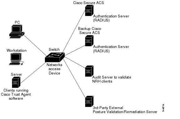
With NAC, the devices in the network have specific roles, as shown in Figure 1 and described below.
•
Note
The CTA software is also referred to as the posture agent or the antivirus client.
•
–
–
Note
•
AS can also function as a third party remediation or audit server for validating the client of the NRH.
Note
Figure 1 NAC Device Roles
Posture Validation
NAC enables NADs to permit or deny network hosts access to the network based on the state of the software on the host. This process is called posture validation.
Posture validation consists of checking the antivirus condition or credentials of the client, evaluating the security posture credentials from the network client, and providing the appropriate network access policy to the NAD based on the system posture.
The Catalyst switch performs posture validation on switch ports as follows ( Figure 1):
1.
2.
If an endpoint is not running the CTA software, the switch classifies the endpoint system as clientless and considers the endpoint system to be a nonresponsive host or a NAC agentless host.
For more information about nonresponsive hosts, see the "Nonresponsive Hosts" section. For more information about clientless endpoint systems and nonresponsive hosts, see the "Posture Validation and Layer 2 IP Validation" section.
For the CTA Administrator Guide 2.0, see this URL:
http://www.cisco.com/en/US/products/ps5923/prod_maintenance_guides_list.htmlFor the Cisco Trust Agent 2.0 Release Notes, see this URL:
http://www.cisco.com/en/US/products/ps5923/prod_release_notes_list.htmlFor the general listing of CTA documentation on the web, see this URL:
http://www.cisco.com/en/US/products/ps5923/tsd_products_support_series_home.html3.
The Cisco Secure ACS validates the antivirus condition of the endpoint, determines the NAC policy, and returns the access policy to the switch. The switch enforces the access policy against the endpoints.
If the validation succeeds, the Cisco Secure ACS grants the client network access based on the access limitations.
If the validation fails, the noncompliant device can be denied access, placed in a quarantined network segment, or given restricted access to computing resources. The validation might fail because either the client is infected with a worm or virus, the host is not running compliant software or the host is using an obsolete version of antivirus software.
For information on Cisco Secure ACS for Windows, see this URL:
http://www.cisco.com/en/US/products/sw/secursw/ps2086/index.htmlFor information on the Cisco Secure ACS solution engine, see this URL:
http://www.cisco.com/en/US/products/sw/secursw/ps5338/index.htmlAAA Down Policy
Typical deployments of NAC use Cisco Secure ACS to validate the client posture and to pass policies back to the NAD. If the AAA server is not reachable when the posture validation occurs, instead of rejecting the user (that is, not providing the access to the network), an administrator can configure a default AAA down policy that can be applied to the host.
This system is advantageous for the following reasons:
•
•
Note
NAC Layer 2 IEEE 802.1X Authentication and Validation
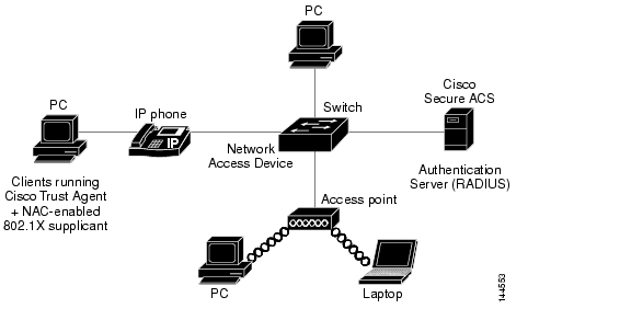
You can use NAC Layer 2 IEEE 802.1X on the access port of an edge switch to which a device (an endpoint system or client) is connected. The device can be a PC, a workstation, a Cisco Aironet access point, or a server that is connected to the switch access port through a direct connection.
Figure 2 Network Using NAC Layer 2 IEEE 802.1X
Either the client or the switch can initiate posture validation. The switch relays EAPOL messages between the endpoints and the Cisco Secure ACS. After the Cisco Secure ACS returns the access control decision, the switch enforces the access limitations either by assigning an authenticated port to a specific VLAN, which provides segmentation and quarantine of poorly postured clients or by denying network access.
This section includes the following topics:
•
•
Nonresponsive Hosts
A nonresponsive host can either be a device running a legacy IEEE 802.1X-compliant supplicant without NAC support or a device without an IEEE 802.1X compliant supplicant. A host or client that does not respond to posture validation requests can be validated in one of these ways:
•
•
If a host with legacy IEEE 802.1X-compliant client software connects to the switch, the switch initiates a session with the Cisco Secure ACS and forwards the host information to the authentication server. The authentication server returns an access policy based on the host's known identity and unknown posture. The policy can be a VLAN assignment or a denial of network access. The switch applies this policy to the host.
The authentication server also sends the switch information that the posture Attribute-Value (AV) pair is set to Unknown because the host did not provide posture information. This information does not affect how the switch applies the access policy to the host.
Periodic Posture Revalidation
Posture changes can occur because of a change to the client or to the Cisco Secure ACS.
•
•
You can configure the switch to periodically revalidate the posture of a responsive host by enabling periodic IEEE 802.1X client re-authentication and specifying its frequency. For devices running a legacy supplicant without CTA, nonresponsive hosts can be configured for periodic posture revalidation.
Note
With NAC Layer 2 IEEE 802.1X, you can specify the number of seconds between re-authentication attempts by manually setting the number of seconds or by configuring the switch to use the value of the Session-Timeout RADIUS attribute in the Access-Accept message from the Cisco Secure ACS.
The switch also uses the Termination-Action RADIUS attribute for posture validation. Depending on the value of this attribute, the switch either automatically revalidates the client or ends the EAPOL-based session, then revalidates the client.
Switch Actions
Depending on the periodic re-authentication state, the re-authentication value, and the Session-Timeout RADIUS attribute, the switch takes one of the actions listed in Table 2.
•
•
•
Note
•
–
–
AAA Down Policy for NAC Layer 2 IEEE 802.1X (Inaccessible Authentication Bypass)
Note
To make use of Inaccessible Authentication Bypass, a port must be designated as a critical port. The process of handling critical ports is as follows:
1.
2.
3.
Note
For information on configuring the Inaccessible Authentication Bypass feature on the Catalyst 3750 and 3560 series switches, refer to the following locations:
http://www.cisco.com/en/US/products/hw/switches/ps5023/products_configuration_guide_chapter09186a00805555e8.html
NAC Layer 2 IP Validation
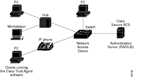
You can use NAC Layer 2 IP on an access port of an edge switch to which a device (an endpoint system or client) is connected. The device can be a PC, a workstation, or a server that is connected to the switch access port through a direct connection, an IP phone, a hub, or a wireless access point, as shown in Figure 3.
Note
When you enable NAC Layer 2 IP, EAPoUDP works only with IPv4 traffic. The switch checks the antivirus condition of the endpoint devices or clients and enforces access control policies.
Figure 3 Network Using NAC Layer 2 IP
This section discusses the following topics:
•
•
•
•
•
Posture Validation and Layer 2 IP Validation
NAC Layer 2 IP supports the posture validation of multiple hosts on the same switch port, as shown in Figure 3.
When you enable NAC Layer 2 IP validation on a switch port to which hosts are connected, the switch can use either DHCP snooping or Address Resolution Protocol (ARP) snooping to identify connected hosts. Posture validation initiated through DHCP snooping takes precedence over posture validation initiated through ARP snooping. The switch initiates posture validation after either receiving an ARP packet or creating a DHCP snooping binding entry.
Note
If dynamic ARP inspection alone is enabled on an access VLAN that is assigned to a switch port, posture validation is initiated when ARP packets pass the dynamic ARP inspection validation checks. If DHCP snooping and dynamic ARP inspection are enabled, however, creating a DHCP snooping binding entry will initiate posture validation.
A malicious host could send spoofed ARP packets and try to bypass posture validation. To prevent unvalidated hosts from accessing the network, you can enable the IP Source Guard feature on the switch port.
Note
When posture validation initiates, a switch creates an entry in the EAPoUDP session table to track the posture validation status of the host and observes the following decision tree to determine the NAC policy:
1.
2.
3.
Exception Lists
An exception list has local profile and policy configurations. Use the identity profile to statically authorize or validate devices based on the IP address, MAC address, or device type. An identity profile is associated with a local policy that specifies the access control attributes.
You can bypass posture validation of specific hosts by specifying those hosts in an exception list and applying a user-configured policy to the hosts. After the entry is added to the EAPoUDP session table, the switch compares the host information to the exception list. If the host is in the exception list, the switch applies the configured NAC policy to the host. The switch also updates the EAPoUDP session table with the validation status of the client as POSTURE ESTAB.
EoU Bypass
The switch can use the EoU bypass feature to speed up posture validation of hosts that are not using the CTA. If EoU bypass is enabled, the switch does not contact the host to request the antivirus condition. Instead, the switch sends a request to the Cisco Secure ACS that includes the IP address, MAC address, service type, and EAPoUDP session ID of the host. The Cisco Secure ACS makes the access control decision and sends the policy to the switch.
If EoU bypass is enabled and the host is nonresponsive, the switch sends a nonresponsive-host request to the Cisco Secure ACS and applies the access policy from the server to the host.
If EoU bypass is enabled and the host uses CTA, the switch also sends a nonresponsive-host request to the Cisco Secure ACS and applies the access policy from the server to the host.
EAPoUDP Sessions
EoU is enabled by default. If the EoU bypass is disabled, the switch sends an EAPoUDP packet to initiate posture validation. While posture validation occurs, the switch enforces the default access policy. After the switch sends an EAPoUDP message to the host and the host responds to the antivirus condition request, the switch forwards the EAPoUDP response to the Cisco Secure ACS. If no response is received from the host after the specified number of attempts, the switch classifies the host as nonresponsive. After the ACS validates the credentials, the authentication server returns an Access-Accept message with the posture token and the policy attributes to the switch. The switch updates the EAPoUDP session table and enforces the access limitations, which provides segmentation and quarantine of poorly postured clients, or by denying network access.
Because of posture validation, two types of policies are applicable on ports:
•
•
–
–
The ACL name for the host policy, the redirect URL, and the URL redirect ACL are conveyed using RADIUS Attribute-Value objects.
Note
Cisco Secure ACS and Attribute-Value Pairs
When you enable NAC Layer 2 IP validation, the Cisco Secure ACS provides NAC authentication, authorization, and accounting (AAA) services by using RADIUS. Cisco Secure ACS gets information about the antivirus credentials of the endpoint system and validates the antivirus condition of the endpoint.
You can set these AV pairs on the Cisco Secure ACS by using the RADIUS cisco-av-pair vendor- specific attributes (VSAs):
•
#ACL#-IP-name-number
where name is the ACL name and number is the version number, such as 3f783768.
The Auth-Proxy posture code checks whether the access control entries (ACEs) of the specified downloadable ACL were previously downloaded. If they were not, the Auth-Proxy posture code sends an AAA request with the downloadable ACL name as the username so that the ACEs are downloaded. The downloadable ACL is then created as a named ACL on the switch. This ACL has ACEs with a source address of any and does not have an implicit deny statement at the end. When the downloadable ACL is applied to an interface after posture validation completes, the source address is changed from any to the host source IP address. The ACEs are prepended to the default ACL applied to the switch interface to which the endpoint device is connected. If traffic matches the CiscoSecure-Defined-ACL ACEs, the appropriate NAC actions are taken.
Whenever you configure ACLs, each entry (ACE) has an action (like "permit"), a protocol (like "ip"), a source part, and a destination part. The host polices, which are the ACLs that the administrator defines either on the ACS or as part of a static policy on the switch, must have "any" as the source address. Otherwise, LPIP won't apply the policy on the switch.
For example, this is a valid expression:
10 permit ip any host 10.1.1.1However, this is an invalid expression:
10 permit ip host 10.1.1.2 host 10.1.1.1Following is an example of an interface ACL:
access-list 115 permit udp any any eq bootps (for bootps requests)access-list 115 permit ip any 20.0.0.0 0.0.0.255 (NAC Ingress source N/W)access-list 115 permit ip any host 40.0.0.5 (Audit Server)•
–
–
These AV pairs enable the switch to intercept an HTTP and/or HTTPS request from the endpoint device and forward the client web browser to the specified redirect address from which the latest antivirus files can be downloaded. The url-redirect AV pair on the Cisco Secure ACS contains the URL to which the web browser will be redirected.
Note
The url-redirect-acl AV pair contains the name or number of an ACL that specifies the HTTP and/or HTTPS traffic to be redirected. The ACL must be defined on the switch. Traffic that matches a permit entry in the redirect ACL is redirected. These AV pairs might be sent if the host's posture is unhealthy.
Note
Following is an example of a url-re-direct-acl:
ip access-list extended url-redirect-aclpermit tcp any <protected-server-vlan-network>For more information about AV pairs that are supported by Cisco IOS software, see the documentation about the software releases running on the AAA clients.
For information on ACS for the Windows Server, see this URL:
http://www.cisco.com/en/US/products/sw/secursw/ps2086/index.htmlFor information on the ACS Solution Engine, see this URL:
http://www.cisco.com/en/US/products/sw/secursw/ps5338/index.htmlAudit Servers
End devices that do not run CTA will not be able to provide credentials when challenged by NADs. Such hosts are termed Agentless or Non-Responsive.
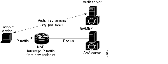
Figure 4 shows how audit servers fit into the typical topology.
Figure 4 NAC Device Roles
To enable you to perform more exhaustive examination of Agentless hosts, the NAC architecture has been extended to incorporate Audit Servers, which can probe and scan these hosts for security compliance, vulnerability and threats without the need for a CTA on the host. The result of the audit can influence Access Servers to make host specific network access policy decisions rather than to enforce a common restrictive policy for all non-responsive hosts. This enables you to build more robust host audit/examination functionality by integrating any 3rd party audit mechanisms into the NAC architecture.
NAC architecture assumes that the Audit Server is reachable so that the host can communicate with it. When a host accesses the network through a NAD configured for posture validation, the NAD requests the AAA server (Cisco Secure ACS) for an access policy to be enforced for the host. You can configure the AAA Server to trigger a scan of the host with an external Audit Sever. The audit scan happens asynchronously and can take several seconds to complete. During this time, the AAA Server would convey a minimal restrictive security policy to the NAD for enforcement along with a short poll timer (Session-Timeout). The NAD would poll the AAA sever at the specified timer interval until the result is available from the Audit Server. Once the AAA server receives the audit, it would compute an access policy based on the audit, which is sent down to the NAD for enforcement on its next request.
Default ACLs
Note
If NAC Layer 2 IP validation is configured on a switch port, a default port ACL must also be configured on a switch port and will be applied to IP traffic.
If the default ACL is configured on the switch and the Cisco Secure ACS sends a host access policy to the switch, the switch applies the policy to traffic from the host connected to a switch port. After the Cisco Secure ACS downloads a per host policy, the incoming traffic is matched against that policy and if there is no match in that policy, the traffic will be matched against the default policy.
If the Cisco Secure ACS sends the switch a downloadable ACL that specifies a redirect URL as a policy-map action, this ACL takes precedence over the default ACL already configured on the switch port. The downloadable ACL always takes precedence over the default ACL. If the default port ACL is not configured on the switch, the downloadable ACLs are not programmed.
NAC Timers
The switch supports these timers:
Hold Timer
The hold timer prevents a new EAPoUDP session from immediately starting after the previous attempt to validate the session fails. This timer is used only when the Cisco Secure ACS sends an Accept-Reject message to the switch.
The default value for the hold timer is 180 seconds (3 minutes).
An EAPoUDP session might not be validated because either the posture validation of the host fails, a session timer expires, or the switch or Cisco Secure ACS receives invalid messages. If the switch or authentication server continuously receives invalid messages, a malicious user might be attempting a denial-of-service attack.
Idle Timer
The idle timer controls how long the switch waits either for an ARP packet from the postured host or for a refreshed entry in the IP device tracking table to verify that the host is still connected. The idle timer works with a list of known hosts to track those that have initiated posture validation and the IP device tracking table.
The idle timer is reset when a switch receives an ARP packet or when an entry in the IP device tracking table is refreshed. If the idle timer expires, the switch ends the EAPoUDP session on the host, and the host is no longer validated.
Note
The default probe interval is 30 seconds. The timeout is actually probe interval times the number of probe entries. So, by default value of the idle timer is 90 seconds, because the probe interval is 30 seconds and the probe retries are 3.
The switch maintains a list of known hosts to track hosts that have initiated posture validation. When the switch receives an ARP packet, it resets the aging timers for the list and the idle timer. If the aging time of the list expires, the switch sends an ARP probe to verify that the host is present. If the host is present, it sends a response to the switch. The switch updates the entry in the list of known hosts. It then resets the aging timers for the list and the idle timer. If switch receives no response, the switch ends the session with the Cisco Secure ACS, and the host is no longer validated.
The switch also uses the IP device tracking table to detect and manage hosts connected to the switch. The switch uses ARP or DHCP snooping to detect of hosts. By default, the IP device tracking feature is disabled on a switch. When IP device tracking is enabled, and a host is detected, the switch adds an entry to the IP device tracking table that includes this information:
•
•
•
If NAC Layer 2 IP validation is enabled on an interface, adding an entry to the IP device tracking table initiates posture validation.
For the IP device tracking table, you can configure the number of times that the switch sends ARP probes for an entry before removing an entry from table and the number of seconds that the switch waits before resending the ARP probe. If the switch uses the default settings of the IP device tracking table, the switch sends ARP probes every 30 seconds for all the entries. When the host responds to the probe, the host state is refreshed and remains ACTIVE. The switch can send up to three additional ARP probes at 30 second intervals if the switch does not get a response. After the maximum number of ARP probes are sent, the switch removes the host entry from the table. The switch ends the EAPoUDP session for the host if a session was set up.
Using the IP device tracking ensures that hosts are detected in a timely manner, despite the limitations of using DHCP. If a link goes down, the IP device tracking entries associated with the interface are not removed, and the state of entries is changed to INACTIVE. The switch does not limit the number of entries in the IP device tracking table but applies a limit to remove INACTIVE entries. All entries remain in the IP device tracking table until it reaches the limit. When the table reaches the limit, the switch removes the INACTIVE ones if the table has INACTIVE entries, and the switch adds new entries. If the table does not have INACTIVE entries, the number of entries in the IP device tracking table continues to increase. When a host becomes INACTIVE, the switch ends the host session.
•
•
After an interface link is restored, the switch sends ARP probes for each entry associated with the interface. The switch ages out entries for hosts that do not respond to ARP probes. The switch also changes the state of hosts that respond to ACTIVE and initiates posture validation.
Retransmission Timer
The retransmission timer controls the amount of time that the switch waits for a response from the client before resending a request during posture validation. Setting the timer value too low might cause unnecessary transmissions, and setting the timer value too high might cause poor response times.
The default value of the retransmission timer is 3 seconds.
Revalidation Timer
The revalidation timer controls the amount of time a NAC policy is applicable to a client that used EAPoUDP messages during posture validation. The timer starts after the initial posture validation completes. The timer resets when the host is revalidated. The default value of the revalidation timer is 36000 seconds (10 hours).
You can specify the revalidation timer value on the switch and on an interface on that switch with the eou timeout revalidation global configuration command.
Note
The revalidation timer behavior is based on Session-Timeout RADIUS attribute and the Termination-Action RADIUS attribute in the Access-Accept message from the Cisco Secure ACS running AAA. If the switch receives the Session-Timeout value, this value overrides the revalidation timer value on the switch.
If the revalidation timer expires, the switch action depends on the value of the Termination-Action attribute:
•
•
•
•
Status-Query Timer
The status-query timer controls the amount of time the switch waits before verifying that the previously validated client is present and that its posture has not changed. Only clients that were authenticated with EAPoUDP messages use this timer, which starts after the client is initially validated. The default value of the status-query timer is 300 seconds (5 minutes).
The timer resets when the host is re-authenticated. When the timer expires, the switch checks the host posture validation by sending a Status-Query message to the host. If the host sends a message to the switch that the posture has changed, the switch revalidates the posture of the host.
NAC Layer 2 IP Validation and Switch Stacks
Note
When the new stack master is elected, all the previously validated hosts connected to the switch stack must be revalidated if NAC Layer 2 IP is still enabled on interfaces to which the hosts are connected. If NAC Layer 2 IP is disabled on the interfaces, the previously validated hosts cannot be revalidated.
NAC Layer 2 IP Validation and Redundant Modular Switches
Note
When RPR mode redundancy is configured, a switchover will lose all information regarding currently postured hosts. When SSO mode redundancy is configured, a switchover will trigger a reposturing of all currently postured hosts.
AAA Down Policy for NAC Layer 2 IP Validation
Note
For the AAA Down Policy, the system works as follows:
1.
2.
3.
Note
NAC Configuration Guidelines and Restrictions
This section contains these configuration guidelines and restrictions:
•
•
NAC Layer 2 IEEE 802.1x Guidelines, Limitations, and Restrictions
Note
The following items apply to the VLAN assigned to the port by the ACS server:
–
–
–
If the VLAN type in the Access-Accept message does not match the VLAN type of the switch port to which the client is assigned, the VLAN assignment fails.
When assigning a port to a private VLAN, specify the secondary private VLAN. The switch determines the primary private VLAN by using the primary- and secondary-private-VLAN associations on the switch.
•
•
•
To support NAC, Access points must be configured for EAP authentication and VLANs.
For instructions on configuring EAP authentication on access points, refer to the "Configuring Authentication Types" chapter in
Cisco IOS Software Configuration Guide for Cisco Aironet Access Points :
http://www.cisco.com/en/US/products/hw/wireless/ps430/products_configuration_guide_chapter09186a00804e7d09.htmlFor instructions on configuring VLANs on access points, refer to the "Configuring VLANs" chapter in Cisco IOS Software Configuration Guide for Cisco Aironet Access Points:
http://www.cisco.com/en/US/products/hw/wireless/ps430/products_configuration_guide_chapter09186a00804e7d4e.html•
–
–
–
•
NAC Layer 2 IP Guidelines, Limitations, and Restrictions
Note
Follow these guidelines, limitations, and restrictions when configuring NAC Layer 2 IP validation:
•
•
•
•
•
•
For information on rate limiting ARP packets, see the discussion of the ip arp inspection limit in the Cisco IOS command reference at the URL:
http://www.cisco.com/univercd/cc/td/doc/product/software/ios123/123cgcr/secur_r/sec_p1g.htm•
•
•
•
•
•
•
•
Note
•
•
•
If IEEE 802.1X authentication is configured on the port, the port cannot send or receive traffic other than EAPOL frames until the client is successfully authenticated.
•
•
•
•
•
•
How to Configure NAC
This section contains the following topics:
•
•
•
•
•
•
•
•
Default NAC Configuration
For the default NAC Layer 2 IEEE 802.1X configuration, see the "Default IEEE 802.1X Configuration" section in the "Configuring 802.1X Port-Based Authentication" chapter of your software configuration guide.
By default, NAC Layer 2 IP validation is disabled.
Configuring NAC Layer 2 IEEE 802.1X
To configure NAC Layer 2 IEEE 802.1X on your Catalyst 4500 series switch, see the "Enabling 802.1X Authentication" and "Configuring Switch-to-Radius-Server Communication" sections in your software configuration guide.) All other tasks listed are optional.
http://www.cisco.com/en/US/products/hw/switches/ps4324/tsd_products_support_series_home.html
For all other switches, see the "Configuring IEEE 802.1X Authentication and Validation" and the "Configuring IEEE 802.1x Authentication Using a RADIUS Server" sections in your software configuration guide.
For the Catalyst 3750 series switch, refer to the URL:
http://www.cisco.com/en/US/products/hw/switches/ps5023/tsd_products_support_series_home.htmlFor the Catalyst 3560 series switch, refer to the URL:
http://www.cisco.com/en/US/products/hw/switches/ps5528/tsd_products_support_series_home.htmlFor the Catalyst 3550 series switch, refer to the URL:
http://www.cisco.com/en/US/products/hw/switches/ps646/tsd_products_support_series_home.htmlFor the Catalyst 2970 series switch, refer to the URL:
http://www.cisco.com/en/US/products/hw/switches/ps5206/tsd_products_support_series_home.htmlFor the Catalyst 2960 series switch, refer to the URL:
http://www.cisco.com/en/US/products/ps6406/tsd_products_support_series_home.htmlFor the Catalyst 2955 and 2950 series switches, refer to the URL:
http://www.cisco.com/en/US/products/hw/switches/ps628/tsd_products_support_series_home.htmlFor the Catalyst 2940 series switch, refer to the URL:
http://www.cisco.com/en/US/products/hw/switches/ps5213/tsd_products_support_series_home.htmlConfiguring NAC Layer 2 IP Validation
To configure NAC Layer 2 IP validation, follow these steps:
To configure the auth-proxy posture code to not get security associations from the AAA server, use the no aaa authorization auth-proxy default global configuration command.
To clear all NAC client device entries on the switch or on the specified interface, use the clear eou privileged EXEC command. To clear entries in the IP device tracking table, use the
clear ip device tracking privileged EXEC command.This example shows how to configure NAC Layer 2 IP validation on a switch interface:
Switch# configure terminalEnter configuration commands, one per line. End with CNTL/Z.Switch(config)# ip admission name nac eapoudpSwitch(config)# access-list 5 permit any anySwitch(config)# interface gigabitethernet 2/0/1Switch(config-if)# ip access-group 5 inSwitch(config-if)# ip admission name nacSwitch(config-if)# exitSwitch(config)# aaa new-modelSwitch(config)# aaa authentication eou default group radiusSwitch(config)# ip device trackingSwitch(config)# ip device tracking probe count 2Switch(config)# radius-server host admin key rad123Switch(config)# radius-server vsa send authenticationSwitch(config)# eou loggingSwitch(config)# endSwitch# show ip admission configurationAuthentication global cache time is 60 minutes Authentication global absolute time is 0 minutes Authentication global init state time is 2 minutes Authentication Proxy Watch-list is disabledAuthentication Proxy Rule ConfigurationAuth-proxy name naceapoudp list not specified auth-cache-time 60 minutesSwitch# show ip device tracking allIP Device Tracking = Enabled--------------------------------------------------------------IP Address MAC Address Interface STATE--------------------------------------------------------------10.5.0.25 0060.b0f8.fbfb GigabitEthernet1/0/4 ACTIVEConfiguring EAPoUDP
EAPoUDP is the protocol that NAC Layer 2 IP uses to exchange posture information with the endpoint system. To fine tune the EAPoUDP state machine parameters, follow steps:
To return to the global default EAPoUDP values, use the no forms of the eou global configuration commands. To disable the EAPoUDP associations, use the no forms of the eou interface configuration commands.
This example shows how to configure EAPoUDP on a switch interface:
Switch# configure terminalEnter configuration commands, one per line. End with CNTL/Z.Switch(config)# eou loggingSwitch(config)# eou allow clientlessSwitch(config)# eou timeout revalidation 2400Switch(config)# eou revalidateSwitch(config)# interface gigabitEthernet 1/0/4Switch(config-if)# eou timeout status-query 600Switch(config-if)# endSwitch# show eouGlobal EAPoUDP Configuration----------------------------EAPoUDP Version = 1EAPoUDP Port = 0x5566Clientless Hosts = EnabledIP Station ID = DisabledRevalidation = EnabledRevalidation Period = 2400 SecondsReTransmit Period = 3 SecondsStatusQuery Period = 300 SecondsHold Period = 180 SecondsAAA Timeout = 60 SecondsMax Retries = 3EAP Rate Limit = 20EAPoUDP Logging = EnabledInterface Specific EAPoUDP Configurations-----------------------------------------Interface GigabitEthernet1/0/4StatusQuery Period = 600 SecondsConfiguring Identity Profiles and Policies
To configure the identity profile and policy, follow these steps:
Note
This example shows how to configure a profile that will authorize a host based on IP address, and associate a local policy with that host:
Switch# configure terminalEnter configuration commands, one per line. End with CNTL/Z.Switch(config)# identity policy policy1Switch(config-identity-policy)# access-group group1Switch(config)# identity profile eapoudpSwitch(config-identity-prof)# device authorize ip address 10.10.142.25 policy policy1Switch(config-identity-prof)# exitSwitch(config)# endSwitch# show identity policyPolicy Name ACL Redirect ACL Redirect URL===============================================================================policy1 group1 NONE NONESwitch# show identity profileNo identity profile of type default is configured.No identity profile of type dot1x is configured.Service Type: eapoudpDevice / Address / Mask Allowed Policy==============================================================10.5.0.99 / 0.0.0.0 Authorized policy1Configuring IP Device Tracking
Note
NAC Layer 2 IP validation does not use an intercept ACL to define a subset of traffic that triggers posture validation. (This is different from Layer 3 implementations.) Instead, the IP Device Tracking table is used to track new hosts as they appear on the network. The IP Device Tracking table detects hosts through the following mechanisms:
•
•
IP ARP Inspection is enabled automatically when IP Device Tracking is enabled. It detects the presence of new hosts by monitoring ARP packets. IP DHCP Snooping, if enabled, detects the presence or removal of new hosts when DHCP assigns or revokes their IP addresses.
Note
Once a device is added to the IP Device Tracking table, the device is monitored through periodic ARP probes. Hosts that fail to respond to these probes are removed from the Device Tracking table.
Note
To configure IP Device Tracking, follow these steps:
The following example shows how to configure IP Device Tracking:
Switch# configure terminalEnter configuration commands, one per line. End with CNTL/Z.Switch(config)# ip device trackingSwitch(config)# ip device tracking probe count 3Switch(config)# ip device tracking probe interval 60Switch(config)# endSwitch# show ip device tracking allIP Device Tracking = Enabled--------------------------------------------------------------IP Address MAC Address Interface STATE--------------------------------------------------------------8.0.0.1 0060.b0f8.fbfb GigabitEthernet1/0/4 ACTIVE
Note
Configuring IP DHCP Snooping for NAC (Optional)
If DHCP is required as a trigger/device learning mechanism for Layer 2 IP Validation, you must configure IP DHCP Snooping. The DHCP Snooping should be enabled on the both voice and data VLAN of the switchport where IP Admission is enabled.
To configure IP DHCP Snooping, follow these steps:
The following example shows how to configure IP DHCP Snooping for NAC:
Switch# configure terminalEnter configuration commands, one per line. End with CNTL/Z.Switch(config)# ip dhcp snoopingSwitch(config)# ip dhcp snooping vlan 8Switch(config)# endSwitch# show ip dhcp snoopingSwitch DHCP snooping is enabledDHCP snooping is configured on following VLANs:1,10,1001Insertion of option 82 is enabledOption 82 on untrusted port is not allowed Verification of hwaddr field is enabledInterface Trusted Rate limit (pps)------------------------ ------- ----------------Switch# show ip dhcp snooping bindingMacAddress IpAddress Lease(sec) Type VLAN Interface------------------ --------------- ---------- ------------- ---- --------------------00:60:B0:F8:FB:FB 8.0.0.1 79464 dhcp-snooping 8 GigabitEthernet1/0/4Total number of bindings: 1If you intend to use IP ARP Inspection alone, then one of the following preconditions should apply:
•
•
•
Configuring IP ARP Inspection with an ARP-filter List (Optional)
This task enables the learning of Layer 2 IP devices with static IP address assignments that are subject to dynamic ARP inspection validation checks.
To configure IP ARP Inspection with an ARP-filter list, follow these steps:
The following example shows how to configure IP ARP Inspection with an ARP-filter list:
Switch# configure terminalEnter configuration commands, one per line. End with CNTL/Z.Switch(config)# arp access-list arp-listSwitch(config-arp-nacl)# deny ip host 101.50.1.54 mac anySwitch(config-arp-nacl)# deny ip host 101.50.1.51 mac anySwitch(config-arp-nacl)# permit ip 101.50.1.0 0.0.0.255 mac anySwitch(config-arp-nacl)# exitSwitch(config)# ip arp inspection vlan 101Switch(config)# ip arp inspection filter arp-acl vlan 101Switch(config)# endSwitch# show ip arp inspection vlan 101Source Mac Validation : DisabledDestination Mac Validation : DisabledIP Address Validation : DisabledVlan Configuration Operation ACL Match Static ACL---- ------------- --------- --------- ----------101 Enabled Active arp-acl NoVlan ACL Logging DHCP Logging---- ----------- ------------101 Deny DenySwitch# show ip arp inspection statisticsVlan Forwarded Dropped DHCP Drops ACL Drops---- --------- ------- ---------- ---------101 9 2 0 4Vlan DHCP Permits ACL Permits Source MAC Failures---- ------------ ----------- -------------------101 9 0 0Vlan Dest MAC Failures IP Validation Failures Invalid Protocol Data---- ----------------- ---------------------- ---------------------101 0 0 0Configuring IP ARP Inspection with IP DHCP Snooping (Optional)
This enables Layer 2 IP device learning to be subject to ARP Inspection feature validation checks. By default the ARP packets are validated using DHCP Snooping bindings.
Note
To configure IP ARP Inspection with IP DHCP Snooping, follow these steps:
Note
The following example shows how to configure IP ARP Inspection with IP DHCP Snooping:
Switch# configure terminalEnter configuration commands, one per line. End with CNTL/Z.Switch(config)# ip dhcp snooping vlan 8Switch(config)# ip arp inspection vlan 8Switch(config)# endSwitch# show ip arp inspection vlan 8Source Mac Validation : DisabledDestination Mac Validation : DisabledIP Address Validation : DisabledVlan Configuration Operation ACL Match Static ACL---- ------------- --------- --------- ----------8 Enabled ActiveVlan ACL Logging DHCP Logging---- ----------- ------------8 Deny DenySwitch# show ip arp inspection statistics vlan 8Vlan Forwarded Dropped DHCP Drops ACL Drops---- --------- ------- ---------- ---------8 4 0 0 0Vlan DHCP Permits ACL Permits Source MAC Failures---- ------------ ----------- -------------------8 4 0 0Vlan Dest MAC Failures IP Validation Failures Invalid Protocol Data---- ----------------- ---------------------- ---------------------8 0 0Configuring a NAC AAA Down Policy (Optional)
Note
To configure NAC AAA down policy, follow these steps:
The following example illustrates how to apply a AAA down policy:
Switch# configure terminalEnter configuration commands, one per line. End with CNTL/Z.Switch(config)# ip admission name AAA_DOWN eapoudp event timeout aaa policy identity global_policySwitch(config)# aaa new-modelSwitch(config)# aaa authorization network default localSwitch(config)# aaa authentication eou default group radiusSwitch(config)# identity policy global_policySwitch(config-identity-policy)# acSwitch(config-identity-policy)# access-group global_aclSwitch(config)# ip access-list extended global_aclSwitch(config-ext-nacl)# permit ip any anySwitch(config-ext-nacl)# exitSwitch(config)# radius-server host 40.0.0.4 test username administrator idle-time 1 key ciscoSwitch(config)# radius-server dead-criteria tries 3Switch(config)# radius-server vsa send authenticationSwitch(config)# radius-server attribute 8 include-in-access-reqSwitch(config)# int fastEthernet 2/13Switch(config-if)# ip admission AAA_DOWNSwitch(config-if)# exitSwitch# show ip admission configurationAuthentication global cache time is 60 minutes Authentication global absolute time is 0 minutes Authentication global init state time is 2 minutes Authentication Proxy Watch-list is disabledAuthentication Proxy Rule ConfigurationAuth-proxy name AAA_DOWNeapoudp list not specified auth-cache-time 60 minutesIdentity policy name global_policy for AAA fail policySwitch# show aaa serversRADIUS: id 1, priority 1, host 40.0.0.4, auth-port 1645, acct-port 1646State: current UP, duration 5122s, previous duration 9sDead: total time 79s, count 3Authen: request 158, timeouts 14Response: unexpected 1, server error 0, incorrect 0, time 180msTransaction: success 144, failure 1Author: request 0, timeouts 0Response: unexpected 0, server error 0, incorrect 0, time 0msTransaction: success 0, failure 0Account: request 0, timeouts 0Response: unexpected 0, server error 0, incorrect 0, time 0msTransaction: success 0, failure 0Elapsed time since counters last cleared: 2h13mSwitch#show aaa method-lists authentication authen queue=AAA_ML_AUTHEN_LOGIN authen queue=AAA_ML_AUTHEN_ENABLE authen queue=AAA_ML_AUTHEN_PPP authen queue=AAA_ML_AUTHEN_SGBP authen queue=AAA_ML_AUTHEN_ARAP authen queue=AAA_ML_AUTHEN_EAPOUDPname=default valid=1 id=0 state=ALIVE : SERVER_GROUP radius authen queue=AAA_ML_AUTHEN_DOT1Xname=default valid=1 id=0 state=ALIVE : SERVER_GROUP radius permanent listsname=Permanent Enable None valid=1 id=0 ALIVE : ENABLE NONEname=Permanent Enable valid=1 id=0 ALIVE : ENABLEname=Permanent None valid=1 id=0 ALIVE : NONEname=Permanent Local valid=1 id=0 ALIVE : LOCALDisplaying NAC Information
Note
To display NAC information, use one of the following privileged EXEC commands:
This example shows the sample output when a new host is detected:
00:45:15: %EOU-6-SESSION: IP=10.5.0.25| HOST=DETECTED| Interface=GigabitEthernet1/0/400:45:15: %EOU-6-CTA: IP=10.5.0.25| CiscoTrustAgent=DETECTED00:45:16: %EOU-6-POLICY: IP=10.5.0.25| TOKEN=Healthy00:45:16: %EOU-6-POLICY: IP=10.5.0.25| URL=http://10.5.0.4300:45:16: %EOU-6-POLICY: IP=10.5.0.25| URL ACL=s-acl00:45:16: %EOU-6-POLICY: IP=10.5.0.25| ACLNAME=#ACSACL#-IP-Healthy-42dbdd9d00:45:16: %EOU-6-POLICY: IP=10.5.0.25| HOSTNAME=CMELTER-XP:dsbu00:45:16: %EOU-6-POSTURE: IP=10.5.0.25| HOST=AUTHORIZED| Interface=GigabitEthernet1/0/400:45:16: %EOU-6-AUTHTYPE: IP=10.5.0.25| AuthType=EAPSwitch# show eou all-------------------------------------------------------------------------Address Interface AuthType Posture-Token Age(min)-------------------------------------------------------------------------10.5.0.25 GigabitEthernet1/0/4 EAP Healthy 0Switch# show eou ip 10.5.0.25Address : 10.5.0.25MAC Address : 0060.b0f8.fbfbInterface : GigabitEthernet1/0/4AuthType : EAPAudit Session ID : 0000000000296E2E000000040A050019PostureToken : HealthyAge(min) : 0URL Redirect : http://10.5.0.43URL Redirect ACL : s-aclACL Name : #ACSACL#-IP-Healthy-42dbdd9dUser Name : HOST-XP:dsbuRevalidation Period : 600 SecondsStatus Query Period : 600 SecondsCurrent State : AUTHENTICATEDClearing EAPoUDP Session Table
To clear client entries in the EAPoUDP session table, use the clear eou privileged EXEC command. After the entries are removed, they are created only after the switch receives an ARP packet from the host or after it creates a DHCP snooping binding entry for the host. To clear entries in the IP device tracking table on the switch, use the clear ip device tracking privileged EXEC command.
Command Reference
Note
This section documents those NAC Layer 2 IP commands that are not generic to Cisco IOS. For documentation on the generic Cisco IOS commands, refer to the following URLs:
http://www.cisco.com/univercd/cc/td/doc/product/software/ios123/123newft/123t/123t_8/gt_nac.htm
and
http://www.cisco.com/univercd/cc/td/doc/product/software/ios123/123cgcr/secur_r/sec_p1g.htm
aaa authentication eou
To set Extensible Authentication Protocol over UDP (EAPoUDP or EoU) authentication methods on the switch, use the aaa authentication eou global configuration command. Use the no form of this command to remove the authentication methods.
aaa authentication eou default group radius
no aaa authentication eou default
Syntax Description
This command has no arguments or keywords.
Defaults
No EAPoUDP authentication methods are configured.
Command Modes
Global configuration
Command History
Usage Guidelines
After configuring ACLs and defining the IP Network Admission Control (NAC) rule, you can configure EAPoUDP authentication methods on a switch. You can also set the authentication proxy methods by using the aaa authorization auth-proxy default group radius global configuration command.
Examples
This example shows how to set EAPoUDP authentication methods:
Switch(config)# aaa authentication eou default group radiusYou can verify your settings by entering the show running-config privileged EXEC command.
Related Commands
aaa authorization auth-proxy default
To enable the auth-proxy posture code to get security associations from the authentication, authorization, and accounting (AAA) server, use the aaa authorization auth-proxy default global configuration command. Use the no form of this command to disable this feature.
aaa authorization auth-proxy default group radius
no aaa authorization auth-proxy default
Note
Syntax Description
This command has no arguments or keywords.
Defaults
The auth-proxy posture code does not get security associations from the AAA server.
Command Modes
Global configuration
Command History
Usage Guidelines
After configuring access control lists (ACLs) and defining the IP Network Admission Control (NAC) rule, set the authentication-proxy authentication methods. You can also set the Extensible Authentication Protocol over UDP (EAPoUDP) authentication methods on a switch by using the aaa authentication eou default group radius global configuration command.
Examples
This example shows how to get security associations from the AAA server:
Switch(config)# aaa authorization auth-proxy default group radiusYou can verify your settings by entering the show running-config privileged EXEC command.
Related Commands
clear ip admission
To clear IP admission entries on the switch, use the clear ip admission privileged EXEC command.
clear ip admission {{cache | watch-list} {* | ip-address}}
Syntax Description
cache
Delete the IP admission cache entries.
watch-list
Delete the IP admission watch-list entries.
*
Delete all the cache entries.
ip-address
Delete the cache entry for the specified IP address.
Defaults
There is no default setting.
Command Modes
Privileged EXEC
Command History
Examples
This example shows how to clear all IP admission cache entries:
Switch# clear ip admission *You can verify your settings by entering the show eou or show ip admission privileged EXEC command.
Related Commands
clear ip device tracking
To clear entries in the IP device tracking table on the switch, use the clear ip device tracking privileged EXEC command.
clear ip device tracking {all | interface interface-id | ip ip-address | mac mac-address}
Syntax Description
Defaults
There is no default setting.
Command Modes
Privileged EXEC
Command History
Usage Guidelines
After you use the clear ip device tracking privileged EXEC command to clear IP device tracking entries, the switch sends ARP probes to the hosts that were removed. If a host is present, it responds to the ARP probe, and the switch add an IP device tracking entry for the host.
Examples
This example shows how to clear all entries in the IP device tracking table:
Switch# clear ip device tracking allYou can verify your settings by entering the show ip device tracking privileged EXEC command.
Related Commands
Enables the IP device tracking table and configures the parameters for the IP device tracking table.
Displays information about the entries in the IP device tracking table.
debug eou
To enable debugging of Extensible Authentication Protocol over UDP (EAPoUDP), use the debug eou privileged EXEC command. Use the no form of this command to disable debugging.
debug eou {all | eap | errors | events | obj-create | obj-destroy | obj-link | obj-unlink | packets | ratelimit | sm}
no debug eou {all | eap | errors | events | obj-create | obj-destroy | obj-unlink | packets | ratelimit | sm}
Syntax Descriptionno debug eou {all | eap | errors | events | packets | ratelimit | sm}
Defaults
Debugging is disabled.
Command Modes
Privileged EXEC
Command History
Usage Guidelines
The undebug eou command is the same as the no debug eou command.
On Catalyst 3750 switches and EtherSwitch service modules, when you enable debugging, it is enabled only on the stack master. To enable debugging on a stack member, you can start a session from the stack master by using the session switch-number privileged EXEC command. Then enter the debug command at the command-line prompt of the stack member. You can also use the remote command stack-member-number LINE privileged EXEC command on the stack master switch to enable debugging on a member switch without first starting a session.
Related Commands
debug ip admission
To enable debugging of IP admission events, use the debug ip admission privileged EXEC command. Use the no form of this command to disable debugging.
debug ip admission {api | dos | eapoudp | function-trace | object-creation | object-deletion | timers}
no debug ip admission {api | dos | eapoudp | function-trace | object-creation | object-deletion | timers}
Syntax Description
Defaults
Debugging is disabled.
Command Modes
Privileged EXEC
Command History
Usage Guidelines
The undebug ip admission command is the same as the no debug ip admission command.
On Catalyst 3750 switches and EtherSwitch service modules, when you enable debugging, it is enabled only on the stack master. To enable debugging on a stack member, you can start a session from the stack master by using the session switch-number privileged EXEC command. Then enter the debug command at the command-line prompt of the stack member. You also can use the remote command stack-member-number LINE privileged EXEC command on the stack master switch to enable debugging on a member switch without first starting a session.
Related Commands
debug ip device tracking
To enable debugging of Network Admission Control (NAC) tracking on switch ports, use the
debug ip device tracking privileged EXEC command. Use the no form of this command to disable debugging.debug ip device tracking {all | events | obj-create | obj-destroy | redundancy}
no debug ip device tracking {all | events | obj-create | obj-destroy | redundancy}
Syntax Description
Defaults
Debugging is disabled.
Command Modes
Privileged EXEC
Command History
Usage Guidelines
The undebug ip device tracking command is the same as the no debug ip device tracking command.
On Catalyst 3750 switches and EtherSwitch service modules, when you enable debugging, it is enabled only on the stack master. To enable debugging on a stack member, you can start a session from the stack master by using the session switch-number privileged EXEC command. Then enter the debug command at the command-line prompt of the stack member. You also can use the remote command stack-member-number LINE privileged EXEC command on the stack master switch to enable debugging on a member switch without first starting a session.
debug sw-ip-admission
To enable debugging of switch-specific NAC Layer2 IP processing, such as ARP and DHCP binding events, use the debug sw-ip-admission privileged EXEC command. Use the no form of this command to disable debugging.
debug sw-ip-admission [packet]
no debug sw-ip-admission [packet]
Syntax Description
Syntax Description
This command has no keywords or arguments.
Defaults
Debugging is disabled.
Command Modes
Privileged EXEC
Command History
Usage Guidelines
The undebug sw-ip-admission command is the same as the no debug sw-ip-admission command.
On Catalyst 3750 switches and EtherSwitch service modules, when you enable debugging, it is enabled only on the stack master. To enable debugging on a stack member, you can start a session from the stack master by using the session switch-number privileged EXEC command. Then enter the debug command at the command-line prompt of the stack member. You also can use the remote command stack-member-number LINE privileged EXEC command on the stack master switch to enable debugging on a member switch without first starting a session.
Related Commands
description
To enter a description of the identity policy, use the description identity-policy configuration mode command. To clear the description, use the no form of this command without the description.
description line-of-description [line-of-description] [line-of-description] ...
no description line-of-description [line-of-description] [line-of-description] ...
Syntax Description
Defaults
No description is configured.
Command Modes
Identity-policy configuration
Command History
Usage Guidelines
You can enter more than one line of text describing the identity policy.
Examples
This example shows how to enter a description of the identity policy called policy100:
Switch(config)# identity policy policy100Switch(config-identity-policy)# description Admin policy for the engineering groupYou can verify your settings by entering the show running-config privileged EXEC command.
Related Commands
device
To manually authorize or reject a device, use the device identity-profile configuration mode command. Use the no form of this command to return to the default setting.
device {authorize | not-authorize} {ip-address ip-address | mac-address mac-address | type cisco ip phone} [policy policy-name]
no device {authorize | not-authorize} {ip-address ip-address | mac-address mac-address | type cisco ip phone} [policy policy-name]
Syntax Description
Defaults
Devices are not manually authorized or rejected.
Command Modes
Identity-profile configuration
Command History
Usage Guidelines
You must create an identity profile by using the identity profile {default | dot1x | eapoudp} global configuration command before using the device identity-profile configuration command.
Examples
This example shows how to statically authorize a device with a MAC address of 1234.abcd.5678 and a policy called policy1:
Switch(config)# identity profile eapoudpSwitch(config-identity-prof)# device authorize mac-address 1234.abcd.4578 policy policy1You can verify your settings by entering the show running-config privileged EXEC command.
Related Commands
eou initialize
To manually reset Extensible Authentication Protocol over UDP (EAPoUDP) state machines, use the eou initialize privileged EXEC command.
eou initialize {all | authentication {clientless | eap | static} | interface interface-id | ip ip-address | mac mac-address | posturetoken name}
Syntax Description
Defaults
There is no default setting.
Command Modes
Privileged EXEC
Command History
Usage Guidelines
When you enter the eou initialize privileged EXEC command, configured EAPoUDP sessions are reset.
Examples
This example shows how to initiate the reset of all EAPoUDP associations:
Switch# eou initializeYou can verify your settings by entering the show eou privileged EXEC command.
Related Commands
eou max-retry (global and interface configuration)
To specify the number of Extensible Authentication Protocol over UDP (EAPoUDP) revalidation attempts, use the eou max-retry global configuration and interface configuration commands. Use the no form of this command to return to the default setting.
eou max-retry number
no eou max-retry
Syntax Description
number
Number of times the switch tries to revalidate EAPoUDP associations.The range is from 1 to 3.
Defaults
The default number of revalidation attempts is 3.
Command Modes
Global configuration and interface configuration
Command History
Usage Guidelines
You can configure the number of revalidation attempts by using the eou max-retry number global configuration command. You can also use the eou max-retry number interface configuration command to configure the among of revalidation attempts for a specific interface.
Examples
This example shows how to specify the number of revalidation attempts as 2 on a switch-wide basis:
Switch(config)# eou max-retry 2This example shows how to specify the number of revalidation attempts as 1 on an interface:
Switch(config-if)# eou max-retry 1You can verify your settings by entering the show eou privileged EXEC command.
Related Commands
eou ratelimit
To specify the number of simultaneous Extensible Authentication Protocol over UDP (EAPoUDP) posture validations, use the eou ratelimit global configuration command. Use the no form of this command to return to the default setting.
eou ratelimit number
no eou ratelimit
Syntax Description
Defaults
The default is 20 clients.
Command Modes
Global configuration
Command History
Usage Guidelines
If you enter the eou rate-limit 0 command, the rate-limiting feature is disabled.
If the number of clients that can be simultaneously validated is 100 and the switch is connected to 101 clients, the posture validation of the last client (client 101) does not occur until another client ends an EAPoUDP session.
Use the eou default or the no eou ratelimit global configuration command to return to the default setting.
Examples
This example shows how to specify that the number of clients that can be simultaneously validated is 40:
Switch(config)# eou ratelimit 40This example shows how to return to the default setting of 20 clients:
Switch(config-if)# eou defaultYou can verify your settings by entering the show eou privileged EXEC command.
Related Commands
eou revalidate (global and interface configuration)
To enable revalidation of the Extensible Authentication Protocol over UDP (EAPoUDP) associations, use the eou revalidate global configuration and interface configuration commands.
eou revalidate
Syntax Description
This command has no keywords or arguments.
Defaults
There is no default setting.
Command Modes
Global configuration and interface configuration
Command History
Usage Guidelines
You can enable revalidation of the EAPoUDP associations on the switch by using the eou revalidate global configuration command. You can also enable revalidation of the EAPoUDP associations on an interface by using the eou revalidate interface configuration command.
The revalidation timer value is based on Session-Timeout RADIUS attribute (Attribute[27]) and the Termination-Action RADIUS attribute (Attribute[29]) in the Access-Accept message from the Cisco Secure ACS running AAA. If the switch gets the Session-Timeout value, this value overrides the revalidation timer value on the switch.
If the revalidation timer expires, the switch action depends on the value of the Termination-Action attribute:
•
•
•
•
Examples
This example shows how to globally initiate revalidation of the EAPoUDP associations:
Switch(config)# eou revalidateThis example shows how to initiate revalidation of the EAPoUDP associations on an interface:
Switch(config)# interface gigabitethernet 1/0/1Switch(config-if)# eou revalidateYou can verify your settings by entering the show eou privileged EXEC command.
Related Commands
eou revalidate (privileged EXEC)
To manually initiate revalidation of Extensible Authentication Protocol over UDP (EAPoUDP) association, use the eou revalidate privileged EXEC command.
eou revalidate {all | authentication {clientless | eap | static} | interface interface-id | ip ip-address | mac mac-address | posturetoken name}
Syntax Description
Defaults
There is no default setting.
Command Modes
Privileged EXEC
Command History
Usage Guidelines
To manually initiate revalidation of the EAPoUDP associations on the switch, use the eou revalidate privileged EXEC command.
Examples
This example shows how to initiate the revalidation of all EAPoUDP clients:
Switch# eou revalidate allThis example shows how to initiate the revalidation of EAPoUDP clients on a specific interface
Switch# eou revalidate interface gigabitethernet 1/0/2You can verify your settings by entering the show eou privileged EXEC command.
Related Commands
eou timeout (global and interface configuration)
To set the Extensible Authentication Protocol over UDP (EAPoUDP) timers, use the eou timeout global configuration and interface configuration commands. Use the no form of this command to set the default values.
eou timeout {aaa seconds | hold-period seconds | retransmit seconds | revalidation seconds | status-query seconds}
no eou timeout {aaa | hold-period | retransmit | revalidation | status-query}
Syntax Description
Defaults
The default AAA time is 60 seconds (1 minute).
The default hold time is 180 seconds (3 minutes).
The default retransmission time is 3 seconds.
The default revalidation time is 600 seconds (10 minutes).
The default status-query time is 300 seconds (5 minutes).
Command Modes
Global configuration and interface configuration
Command History
Usage Guidelines
You can globally configure the EAPoUDP timers on a switch by entering the eou timeout global configuration command. You can also configure the EAPoUDP timers on a specific interface by entering the eou timeout interface configuration command.
For more information about the EAPoUDP timers, see the "NAC Timers" section.
Examples
This example shows how to set the retransmission timer to 45 seconds on a switch-wide basis:
Switch(config)# eou timeout retransmit 45This example shows how to set the revalidation timer to 800 seconds on an interface:
Switch(config-if)# eou timeout revalidation 800You can verify your settings by entering the show eou privileged EXEC command.
Related Commands
identity policy
To create an identity policy and enter Extensible Authentication Protocol over UDP (EAPoUDP) policy configuration mode, use the identity policy global configuration mode. Use the no form of this command to remove the policy.
identity policy policy-name
no identity policy policy-name
Syntax Description
Defaults
No EAPoUDP policies are configured.
Command Modes
Global configuration
Command History
Usage Guidelines
After a device is manually authenticated based on the IP address, MAC address or based on the device type, you can define the policy to be applied to the device by using the identity policy policy-name global configuration mode. For more information, see the "Configuring Identity Profiles and Policies" section in the "Configuring Network Admission Control" chapter.
Examples
This example shows how to create an identity policy and enter EAPoUDP policy configuration mode:
Switch(config)# identity policy policy11You can verify your settings by entering the show running-config privileged EXEC command.
Related Commands
ip admission name eapoudp
To create an IP Network Admission Control (NAC) rule, use the ip admission name eapoudp global configuration command. Use the no form of this command to remove the rule.
ip admission name rule-name eapoudp
no ip admission name rule-name eapoudp
Syntax Description
Defaults
No IP NAC rules are configured.
Command Modes
Global configuration
Command History
Usage Guidelines
The IP NAC rule defines how you apply NAC.
To apply the IP NAC rule on an access port on an edge switch, use the ip admission admission-name interface configuration command.
Examples
This example shows how to create an IP NAC rule called rule11:
Switch(config)# ip admission name rule11 eapoudpYou can verify your settings by entering the show ip admission privileged EXEC command.
Related Commands
ip admission name eapoudp bypass
To enable and configure the Extensible Authentication Protocol over UDP (EAPoUDP or EoU) bypass feature, use the ip admission name eapoudp bypass global configuration command. Use the no form of this command to remove the rule.
ip admission name rule-name eapoudp bypass {auth-cache-list cache-time [list {acl-name | acl-number}] | list {access-list-name | access-list-number}}
no ip admission name rule-name eapoudp
Syntax Description
Defaults
EoU bypass is disabled.
Command Modes
Global configuration
Command History
Usage Guidelines
When EoU bypass is enabled, the switch does not contact the host to request the antivirus condition. Instead, the switch sends a request to the Cisco Secure Access Control Server (ACS) that includes the IP address, MAC address, service type, and EAPoUDP session ID of the host. The authentication server makes the access control decision and sends the policy to the switch.
You can associate the specified rule with an ACL to control which hosts are authenticated with NAC. If you do not configure a standard ACL, the switch uses the NAC rule to intercept IP traffic from all hosts connected to NAC-enabled ports.
You can use the auth-cache-time cache-time keywords to specify the time at which cache entries expire and the host must be revalidated.
You can use the list {acl-name | acl-number} keywords to specify a named or numbered ACL that is applied to the NAC rule. If IP connections are initiated by hosts in the ACL, the initial connection requests are intercepted by the NAC feature.
Examples
This example shows how to enable EoU bypass and associate it with a numbered ACL. The switch uses NAC to validate the antivirus state of IP traffic that matches the ACL instead of permitting packets that match the ACL.
Switch(config)# ip admission name rule11 eapoudp bypass list 101This example shows how to enable EoU bypass and specify the cache entry timer:
Switch(config)# ip admission name rule11 eapoudp bypass auth-cache-time 30This example shows how to disable EoU bypass:
Switch(config)# ip admission name rule11 eapoudp bypassYou can verify your settings by entering the show ip admission privileged EXEC command.
Related Commands
ip device tracking
To enable the IP device tracking feature and to configure the IP device tracking table parameters, use the ip device tracking global configuration command. Use the no form of this command to disable the feature and to return to the default settings.
ip device tracking [probe {count count | interval interval}]
no ip device tracking [probe {count | interval}]
Syntax Description
Defaults
IP device tracking is disabled.
The default number of times that the switch sends the ARP probe for an entry is 3.
The default number of seconds that the switch waits before resending the ARP probe is 30 seconds.
Command Modes
Global configuration
Command History
Usage Guidelines
For information about the IP device tracking feature and the IP device tracking table, see the "NAC Timers" section.
This example shows how to enable the IP device tracking:
Switch(config)# ip device trackingThis example shows how to set the number of times that the switch sends ARP probes to 4:
Switch(config)# ip device tracking probe count 4You can verify your settings by entering the show ip device tracking privileged EXEC command.
Related Commands
Clears entries in the IP device tracking table on the switch.
Displays information about the entries in the IP device tracking table.
mls rate-limit layer2 ip-admission
Note
To rate limit the IP admission Layer 2 traffic (redirected to the CPU) with the hardware rate limiter, use the mls rate-limit layer2 ip ip-admission global configuration command. Use the no form of this command to disable the feature.
mls rate-limit layer2 ip ip-admission pps [burst]
no mls rate-limit layer2 ip ip-admission
Syntax Description
Defaults
Rate limiting is not enabled.
Command Modes
Privileged EXEC
Command History
Usage Guidelines
The NAC rate limiter is off by default; all the packets matching the scenario are sent to the RP.
Examples
This example shows how to set the packet rate to 1000 packets per second and the burst rate to a maximum of 100 packets:
Switch(config)# mls rate-limit layer2 ip-admission 1000 100radius-server attribute 8
To configure the switch to send Framed-IP-Address RADIUS attribute (Attribute[8]) in access-request or accounting-request packets, use the radius-server attribute 8 global configuration mode. Use the no form of this command to configure the switch to not send the RADIUS attribute (Attribute[8]).
radius-server attribute 8 include-in-access-req
no radius-server attribute 8 include-in-access-req
Syntax Description
This command has no keywords or arguments.
Defaults
The switch does not send the Framed-IP-Address RADIUS attribute (Attribute[8]) in RADIUS access-request or accounting-request packets.
Command Modes
Global configuration
Command History
Usage Guidelines
When the switch validates the posture of nonresponsive hosts, also referred to as Network Admission Control (NAC) agentless hosts, you must use the radius-server attribute 8 include-in-access-req global configuration command.
When you enter the radius-server attribute 8 include-in-access-req global configuration command, the switch sends the Framed-IP-Address attribute in RADIUS access-request or accounting-request packets.
Examples
This example shows how to configure the switch to send the RADIUS attribute (Attribute[8]) in access-request or accounting-request packets:
Switch(config)# radius-server attribute 8 include-in-access-reqYou can verify your settings by entering the show eou privileged EXEC command.
Related Commands
Displays information about the Extensible Authentication Protocol over UDP (EAPoUDP) configuration or session cache entries.
redirect
To specify the URL to which the switch redirects clients, use the redirect configuration mode. Use the no form of this command to remove the URL.
redirect url url [match acl-name]
no redirect url url [match]
Note
Syntax Description
url
Specify the URL to which clients are redirected.
match acl-name
Specify that traffic matching the specified access control list (ACL) is redirected to the URL.
Defaults
No URLs or ACLs are configured.
Command Modes
Identity-policy configuration
Command History
Usage Guidelines
When you specify a redirect URL, an identity policy must be associated with an Extensible Authentication protocol over UDP (EAPoUDP) identity profile.
Examples
This example shows how to create an identity policy called policy100 and enter EAPoUDP policy configuration mode:
Switch(config)# identity policy policy100Switch(config-identity-policy)# redirect tftp:172.20.10.30/nac_authen.tar match authen_policyYou can verify your settings by entering the show running-config privileged EXEC command.
Related Commands
show eou
To display information about the Extensible Authentication Protocol over UDP (EAPoUDP) configuration or session cache entries, use the show eou privileged EXEC command.
show eou {all | authentication {clientless | eap | static} | interface interface-id | ip ip-address | mac mac-address | posturetoken name} [ | {begin | exclude | include} expression]
Syntax Description
Command Modes
Privileged EXEC
Command History
Usage Guidelines
If you do not specify a port, global parameters and a summary appear. If you specify a port, details for that port appear.
Expressions are case sensitive. For example, if you enter | exclude output, the lines that contain output are not displayed, but the lines that contain Output appear.
Examples
This is an example of output from the show eou privileged EXEC command:
Switch# show eouGlobal EAPoUDP Configuration----------------------------EAPoUDP Version = 1EAPoUDP Port = 0x5566Clientless Hosts = DisabledIP Station ID = DisabledRevalidation = EnabledRevalidation Period = 36000 SecondsReTransmit Period = 3 SecondsStatusQuery Period = 300 SecondsHold Period = 180 SecondsAAA Timeout = 60 SecondsMax Retries = 3EAP Rate Limit = 20EAPoUDP Logging = DisabledInterface Specific EAPoUDP Configurations-----------------------------------------Interface GigabitEthernet1/0/1No interface specific configurationTable 4 describes the fields in the display:
Table 4 show eou Field Descriptions
EAPoUDP Version
Displays the EAPoUDP protocol version.
EAPoUDP Port
Displays the EAPoUDP port number.
Clientless Hosts
Displays the status of the clientless hosts (enabled or disabled).
IP Station ID
Displays whether the IP address is allowed in the AAA1 station-id field. By default, this field is disabled.
Revalidation
Displays the revalidation status.
Revalidation Period
Displays the host revalidation interval.
ReTransmit Period
Displays the EAPoUDP packet retransmission interval.
StatusQuery Period
Displays the EAPoUDP status query interval for validated hosts.
Hold Period
Displays the time that the switch waits after NAC authentication fails.
AAA Timeout
Displays the AAA timeout period.
Max Retries
Displays the allowed number of transmissions.
EAPoUDP Logging
Displays the logging status.
1 AAA = authentication, authorization, and accounting
Related Commands
show ip access-lists interface
To display the LP IP host policies, use the show ip access-lists privileged EXEC command.
show ip access-lists interface interface
Syntax Description
Command Modes
Privileged EXEC
Command History
Examples
This is an example of output from the show ip device tracking all privileged EXEC command:
Switch# show ip access-lists GigabitEthernet3/4IP Admission access control entires (Inbound)permit ip host 102.50.1.54 anyshow ip device tracking
To display information about the entries in the IP device tracking table, use the show ip device tracking privileged EXEC command.
show ip device tracking {all | interface interface-id | ip ip-address | mac mac-address} [ | {begin | exclude | include} expression]
Syntax Description
Command Modes
Privileged EXEC
Command History
Usage Guidelines
Expressions are case sensitive. For example, if you enter | exclude output, the lines that contain output are not displayed, but the lines that contain Output appear.
Examples
This is an example of output from the show ip device tracking all privileged EXEC command:
Switch# show ip device tracking all---------------------------------------------------------------IP Address MAC Address Interface STATE---------------------------------------------------------------1.1.1.1 cf2a.220a.12f4 GigabitEthernet1/0/1 ACTIVE1.2.1.1 df4a.1235.ef1a GigabitEthernet1/0/2 INACTIVERelated Commands
Enables the IP device tracking table and to configure the IP device tracking table parameters.
Message and Recovery Procedures
This section contains the following topics:
AP Messages
This section contains the Authentication Proxy messages for Network Admission Control (NAC) Layer 2 IP validation.
•
•
AP-4-POLICY_URL_REDIRECTand theAP-6-POSTURE_POLICYmessages.Error Message AP-4-AUTH_PROXY_NOMEM: Sufficient memory was not available to [chars].Explanation This message means that the system memory is not sufficient to perform the specified operation. [chars] is the operation.
Recommended Action Reduce other system activity to ease memory demands. You can also allocate more memory resources.
Error Message    AP-4-POLICY_URL_REDIRECT: Failed to locate match access control list
[chars] for host [inet].
Explanation This message means that the switch could not redirect the HTTP or HTTPS traffic from the host to the redirect URL. The url-redirect Attribute-Value (AV) pair consists of the redirect URL and an access control list (ACL) called match-all that specifies the HTTP and HTTPS traffic to be redirected. If the ACL is not configured or does not specify the traffic to be redirected, the switch does not redirect requests from the hosts. [inet] is the host IP address.
Recommended Action Configure and apply an ACL on the switch interface to which the host is connected, and ensure that the url-redirect AV pair consists of the redirect URL and the ACL.
Error Message    AP-4-POSTURE_EXCEED_MAX_INIT: Exceeded maximum limit [dec] on entries
in authentication proxy.
Explanation This message means that the number of entries in the authentication proxy posture cache which are in INIT state exceeds the limit. This happens when the switch has an authentication proxy configured for posture validation and the switch receives requests from a large number of unique hosts with source IP addresses. This could be a denial-of-service attack. When the number of entries in the posture cache count is below the maximum, new cache entries can be created. [dec] is the number of entries allowed in the authentication proxy cache.
Recommended Action No action required. When the number of entries in the posture cache count is below the maximum, new cache entries can be created.
Error Message    AP-6-POSTURE_DOWNLOAD_ACL: Send AAA request to download [chars] named
access control list.
Explanation This message means that the switch sent a request to the authentication, authorization, and accounting (AAA) server to get the specified ACL. [chars] is the name or number of the ACL.
Recommended Action No action is required.
Error Message AP-6-POSTURE_POLICY: [chars] [chars] [chars] policy for host [inet].Explanation This message means that the specified policy is enforced or removed for the specified host. The policy is either an access control list (ACL) or a redirect URL. The first and second [chars] are the actions that the switch takes to enforce or remove the policy, and the third [chars] is the ACL or redirect URL.
Recommended Action No action is required.
Error Message AP-6-POSTURE_START_VALIDATION: IP=[inet] | Interface=[chars].Explanation This message means that the switch created an entry for the host in the authentication proxy posture cache and initiated the posture validation process. [inet] is the host IP address, and [chars] is the switch interface to which the host is connected.
Recommended Action No action is required.
Error Message AP-6-POSTURE_STATE_CHANGE: IP=[inet]|STATE=[chars].Explanation This message means that the posture validation state of the specified host in the authentication proxy posture validation cache changed. [inet] is the host IP address. [chars] is the posture validation state.
Recommended Action No action is required.
EOU Messages
These are the Extensible Authentication Protocol over User Datagram Protocol (EAPoUDP or EoU) messages for Network Admission Control (NAC) Layer 2 IP validation.
Note
Error Message EOU-2-PROCESS_ERR: Router could not create a EAPoUDP process.Explanation This message means the switch could not create an EAPoUDP session.
Recommended Action Reload the device.
Error Message EOU-4-BAD_PKT: IP=[inet]| Bad Packet=[chars].Explanation This message means that the router received an invalid EAPoUDP packet from the specified host. [inet] is the host IP address, and [chars] is the information about the bad packet.
Recommended Action Check the NAC Layer 2 IP configuration on the host.
Error Message EOU-4-MSG_ERR: Unknown message event received.Explanation This message means that the EAPoUDP validation process received an unknown message event.
Recommended Action If this message recurs, reload the device.
Error Message EOU-4-PROCESS_STOP: PROCESS=[chars]| ACTION=[chars].Explanation This message means that the specified process stopped. The first [chars] is the process, and the second [chars] is the action taken on the process.
Recommended Action Reload the device.
Error Message    EOU-4-SOCKET: EAPoUDP socket binding fails for PORT=[hex]. Check if
the interface has valid IP address.
Explanation This message means that the switch could not bind the port to a valid IP address. [hex] is the port MAC address.
Recommended Action Configure a valid IP address on the switch port.
Error Message EOU-4-UNKN_EVENT_ERR: UNKNOWN Event for HOST=%i| Event=%d.Explanation This message means that the switch received an unknown EAPoUDP event.
Recommended Action Copy the message exactly as it appears on the console or in the system log. Research and attempt to resolve the error by using the Output Interpreter. Use the Bug Toolkit to look for similar reported problems. If you still require assistance, open a case with the TAC, or contact your Cisco technical support representative, and provide the representative with the gathered information.
Error Message EOU-4-UNKN_PROCESS_ERR: An unknown operational error occurred.Explanation This message means that the EAPoUDP process cannot operate due to an internal system error.
Recommended Action Reload the device.
Error Message EOU-4-UNKN_TIMER_ERR: An unknown Timer operational error occurred.Explanation This message means that the EAPoUDP validation process cannot operate due to an internal system error.
Recommended Action Reload the device.
Error Message    EOU-4-VALIDATION: Unable to initiate validation for HOST=[inet]|
INTERFACE=[chars].
Explanation This message means that the switch could not start posture validation for the specified host.
Recommended Action This is not an action: This is probably due to a failure in binding the EAPoUDP port.
Error Message EOU-4-VERSION_MISMATCH: HOST=[inet] | Version=[dec].Explanation This message means the EAPoUDP versions of the specified host and switch are incompatible. [inet] is the host IP address, and [dec] is the EAPoUDP version of the host.
Recommended Action Check EAPoUDP versions on the devices.
Error Message    EOU-5-RESPONSE_FAILS: Received an EAP failure response from AAA for
host=[inet].
Explanation This message means that the switch received an EAP-failure response from the authentication, authorization, and accounting (AAA) server that the host antivirus condition could not be validated.
Recommended Action No action required.
Error Message EOU-6-AUTHSTATUS: [chars]|[inet].Explanation This message means that the authentication status for the specified host is Success or Failure. [chars] is the status, and [inet] is the host IP address.
Recommended Action No action is required.
Error Message EOU-6-AUTHTYPE: IP=[inet]| AuthType=[chars].Explanation This message means that the authentication type for the specified host is [chars]. [inet] is the host IP address.
Recommended Action No action is required.
Error Message EOU-6-CTA: IP=[inet]| CiscoTrustAgent=[chars].Explanation This message means that the CTA was detected for the specified host. [inet] is the host IP address, and [chars] is the CTA name.
Recommended Action If the CTA was not detected, install it on the host.
Error Message EOU-6-IDENTITY_MATCH: IP=[inet]| PROFILE=EAPoUDP| POLICYNAME=[chars].Explanation This message means that the switch found the specified host with an EAPoUDP identity profile. If the specified policy is enforced, the posture of switch is not validated. [inet] is the host IP address, and [chars] is the policy name.
Recommended Action If you want the posture host to be validated, remove the host entry from the EAPoUDP identity profile.
Error Message EOU-6-POLICY: IP=[inet]| [chars]=[chars].Explanation This message means that the switch received an access policy from the AAA server to enforce against the specified host.
Recommended Action No action is required.
Error Message EOU-6-POSTURE: IP=[inet]| HOST=[chars]| Interface=[chars].Explanation This message means the posture validation status for the specified host changed. [inet] is the host IP address, the first [chars] is the hostname, and the second [chars] is the interface.
Recommended Action No action is required.
Error Message EOU-6-SESSION: IP=[inet]| HOST=[chars]| Interface=[chars].Explanation This message means that an entry was created or deleted for the host on the specified interface. [inet] is the host IP address, the first [chars] is an action, such as DETECTED or REMOVED, and the second [chars] is the interface.
Recommended Action No action is required.
Error Message EOU-6-SQ: IP=[inet]| STATUSQUERY|[chars].Explanation This message means that the result of the status query for the specified host failed or is invalid. [inet] is the host IP address, and [chars] is the result of the status query (failure, invalid, or no response).
Recommended Action No action is required.
This document is to be used in conjunction with the documents listed in the "Related Documentation" section.
CCSP, CCVP, the Cisco Square Bridge logo, Follow Me Browsing, and StackWise are trademarks of Cisco Systems, Inc.; Changing the Way We Work, Live, Play, and Learn, and iQuick Study are service marks of Cisco Systems, Inc.; and Access Registrar, Aironet, ASIST, BPX, Catalyst, CCDA, CCDP, CCIE, CCIP, CCNA, CCNP, Cisco, the Cisco Certified Internetwork Expert logo, Cisco IOS, Cisco Press, Cisco Systems, Cisco Systems Capital, the Cisco Systems logo, Cisco Unity, Empowering the Internet Generation, Enterprise/Solver, EtherChannel, EtherFast, EtherSwitch, Fast Step, FormShare, GigaDrive, GigaStack, HomeLink, Internet Quotient, IOS, IP/TV, iQ Expertise, the iQ logo, iQ Net Readiness Scorecard, LightStream, Linksys, MeetingPlace, MGX, the Networkers logo, Networking Academy, Network Registrar, Packet, PIX, Post-Routing, Pre-Routing, ProConnect, RateMUX, ScriptShare, SlideCast, SMARTnet, StrataView Plus, TeleRouter, The Fastest Way to Increase Your Internet Quotient, and TransPath are registered trademarks of Cisco Systems, Inc. and/or its affiliates in the United States and certain other countries.
All other trademarks mentioned in this document or Website are the property of their respective owners. The use of the word partner does not imply a partnership relationship between Cisco and any other company. (0502R)
Network Admission Control Software Configuration Guide
Copyright © 1999-2005, Cisco Systems, Inc. All rights reserved.
![]()
![]()
![]()
![]()
![]()
![]()
![]()
![]()
Posted: Mon Aug 21 14:08:50 PDT 2006
All contents are Copyright © 1992--2006 Cisco Systems, Inc. All rights reserved.
Important Notices and Privacy Statement.