|
|

This Configuration Note, Version 2.1(1a), contains the following information:
For detailed information about configuring a Catalyst 3000 series ATM Expansion module, refer to the Installation and Configuration Guide of an appropriate model of the Catalyst 3000 series switch.
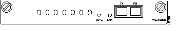
The WS-X3006 is a single-port ATM expansion module that is used to establish a high-speed 155 Mbps ATM connection between Catalyst 3000 Stack devices and ATM networks.
Two versions of the Catalyst 3000 series switch ATM expansion module are now available:
The new WS-X3006B model of the ATM expansion module is installed, configured, and managed the same as the WS-X3006A model (refer to the Installation and Configuration Guide for additional information). The WS-X3006B is identified by the "WS-X3006B SINGLE MODE ATM" label on the faceplate.
The following section describes the cabling specifications for the WS-X3006B ATM expansion module.
The WS-X3006B ATM expansion module cabling specifications are listed in Table 1.
| Function | Specification |
|---|---|
| Optical Specifications: | |
|
-14 to -8 dBm |
|
-32.5 to -8 dBm |
|
1261 to 1360 nm |
|
Laser |
|
6.2 mi (10 km) |
| Fiber Type | 8.3 x 125 micron core |
The WS-X3006 ATM expansion modules perform packet/cell conversions. Incoming data cells enter through the ATM physical interface and are processed by the module and converted to packets at network layer 2. Outbound data is converted from packets to cells and transmitted through the ATM physical interface.
The following table (Table 2) displays the specifications for the WS-X3006 ATM expansion modules.
| Function | Specification |
|---|---|
| Throughput | 65,000 packets per second in each direction |
| Number of VLANS | 64 |
| Number of SVCs | 1912 in each direction |
| Number of PVPs | One |
| Packet Buffers | 512K Bytes in each direction |
| Operating Temperature | 10 to 40 degrees Centigrade |
| Non-operating Temperature | -25 to 75 degrees Centigrade |
| Relative Humidity: operating | 8 to 80%, non-condensing |
| Non-operating Altitude | 40,000 feet |
| Safety | UL 1950
UL-C EN 60950 CE Mark |
| EMI Certifications | FCC Class A (Part 15)
EN 55022 A VCCI Class 1 |
The Catalyst 3000 series expansion modules can be inserted in either of the two expansion slots in the front of a Catalyst 3000 series switch (see Figure 2).
Use the following steps when installing a module into an expansion slot of the Catalyst chassis.
 | Caution The Catalyst 3000 series expansion modules are not hot-swappable. Power must be disconnected from the Catalyst chassis before an expansion module is inserted or removed. |
| **before**Do not touch the components or connectors on the expansion module. Do not touch cable connector pins when the other end is plugged in. Damage may result from static discharge.@@before@@ | Caution **after**Do not touch the components or connectors on the expansion module. Do not touch cable connector pins when the other end is plugged in. Damage may result from static discharge.@@after@@ |
| **before**During installation, the connector on the expansion module must line up evenly with the connector inside the expansion slot. Misalignment may cause the connector pins to bend. When inserting the module into the expansion slot, be sure that the board is level and that the left and right sides slide evenly into the slot.@@before@@ | Caution **after**During installation, the connector on the expansion module must line up evenly with the connector inside the expansion slot. Misalignment may cause the connector pins to bend. When inserting the module into the expansion slot, be sure that the board is level and that the left and right sides slide evenly into the slot.@@after@@ |
Step 1 Disconnect the power to the Catalyst 3000 series switch.
Step 2 If there is a blank cover over the expansion module slot, or if the slot has an installed module, remove it by unscrewing the two attachment screws.
Step 3 Hold the module by the edges to prevent static damage. Be careful not to touch the top or bottom.
Step 4 Slide the module into the slot evenly, taking care to line up the edges with the guides.
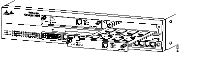
Step 5 Seat the module by pressing the front of the module with your thumbs.
Step 6 Secure the module to the chassis by tightening the thumb (panel) screws at the left and right edges of the expansion modules front panel. Do not overtighten the screws.
Step 7 Return power to the switch.
The ATM expansion module is a full-duplex device. For its multiple VLAN (virtual LAN) features to be enabled, The ATM module must be installed in an enhanced version of the Catalyst switch. Refer to a Catalyst 3000 series Installation and Configuration Guide for more information on the differences between enhanced and unenhanced versions.
(If the ATM module is installed in a unenhanced version of the Catalyst switch, the unit supports creation of a single VLAN within its Stack, but does not support creation of multiple-stack VLANs.)
Use the following information to connect cables to the front of the ATM module:
Observe the following warnings and notes when cabling an expansion module with fiber-optic cable:
 | Warning Laser radiation is present when the system is open. |
Warning Do not stare into the laser beam.
Step 1 Determine that you have the proper cable.
Step 2 Connect an ATM cable from a switch or network device to the SC Duplex ports on the front of the expansion module.
Step 3 Verify that the connection has the proper polarity. Be sure the Tx connector on the ATM module is linked to the Rx connector on the other device, and that the Rx connector on the ATM module is linked to the Tx connector on the other device. (ATM Duplex SC connectors are "keyed" to indicate proper polarity, but the polarity of your connector cables may not be clearly marked.)
The following tables (Table 3 and Table 4) describe the connectors, LEDs, and switches on the WS-X3006A/B module.
| Name | Description |
| LINK | Off = link not detected
Green = link detected |
| DIAG | Running self-diagnostic or if ATM module fails |
| Name | Description |
| Network Port | SC type optical fiber connector |
When the link is established, the LINK LED is on. The LED should be green. If the LED is not on, or if the LED is an amber color, try the following tests:
If the above tests do not correct the problem, contact Cisco support.
If, after installation, there is poor system performance or the ATM module does not work at all, remove the module and check for any damage or bent connector pins. You may need a bright light to see inside the expansion module slot to check for bent pins. If you cannot find an immediate cause for the problem, contact Cisco support.
For service and support for a product purchased from a reseller, contact the reseller. Resellers offer a wide variety of Cisco service and support programs, which are described in the section "Service and Support" in the information packet that shipped with your product.
For service and support for a product purchased directly from Cisco, use CCO.
CCO is Cisco Systems' primary, real-time support channel. SMARTnet customers and partners can self-register on CCO to obtain additional information and services.
Available 24 hours a day, 7 days a week, CCO provides a wealth of standard and value-added services to Cisco's customers and business partners. CCO services include product information, product documentation, software updates, release notes, technical tips, the Bug Navigator, configuration notes, brochures, descriptions of service offerings, and download access to public and authorized files.
CCO serves a wide variety of users through two interfaces that are updated and enhanced simultaneously: a character-based version and a multimedia version that resides on the World Wide Web (WWW). The character-based CCO supports Zmodem, Kermit, Xmodem, FTP, and Internet e-mail, and it is excellent for quick access to information over lower bandwidths. The WWW version of CCO provides richly formatted documents with photographs, figures, graphics, and video, as well as hyperlinks to related information.
You can access CCO in the following ways:
For a copy of CCO's Frequently Asked Questions (FAQ), contact cco-help@cisco.com. For additional information, contact cco-team@cisco.com.
Please use CCO to obtain general information about Cisco Systems, Cisco products, or upgrades. If CCO is not accessible, contact 800 553-6387, 408 526-7208, or cs-rep@cisco.com.
|
|