|
|

The 2.0(3) software release supports the existing Catalyst 3000 switch family and CPW1601, and supports the following features:
 | Caution If you are upgrading a pre 2.0 system, you MUST upgrade the bootcode first. If you do not, the system will not boot when restarted. |
RMON, Vlans, Spanning tree and ISL are all supportable in a Stack of 4MB boxes.
There are, however, some restrictions when you use switches with 4MB of memory.
For a single unit or a Stack:
For a Stack:
The following is a list of certain system configuration limitations when using 2.0(or above) software.
NMS applications may need to be reconfigured for longer Polling Frequencies and Timeouts when accessing a large, very heavily loaded Stack.
The following are known conditions as of this version of the software release.
After exiting the Port Statistics menu, the screen may still refresh itself when the switch is under heavy traffic. To solve this problem, re-enter the menu and exit it again.
The statistic, Maximum Number of Stations, displayed in the VLAN Switch Statistics menu is actually the maximum number of stations for the switch, not the VLAN.
The Maximum Number of Stations is not related to the two other statistics, Current Number of Stations and Most Number of Stations, displayed in the VLAN Statistics menu. Due to differences as to which stations are included in the maximum count, the Maximum Number of Stations could show a lower number than the other statistics.
The following conditions have been corrected with this version of the software release.
CSCdi91965 : Port Config Menu shows the wrong type for 3-port 10Base2 card
CSCdi87901 : Indicates full duplex on port config menu for 3-port 10Base2 card
CSCdj03158 : Display the boot image version
CSCdi93137 : Lane config menus can be accessed from console/telnet @ same time
CSCdj02361 : Invalid data on signalling/ILMI channels
CSCdi87974 : Default LEC does not do shutdown completely
CSCdi83924 : Add a new LEC uptime counter to LANE client screen
CSCdj04384 : VLAN LEC autocreation feature when def VLAN deleted
CSCdi80952 : Moderate problem with LEC creation on one-trunk system
CSCdi79694 : Bring up ELAN w/ no local ports if IP interface is up
CSCdj03255 : LANE Svr Crash: STP:CPU BUFF TO NET BUF- NO MORE MEM
CSCdi80560 : WARNING:eps_send:No network buffer available
CSCdi92434 : IP semaphore grabbed and not released in certain situations
CSCdj04617 : Enhancement request-- Please set default IP state as disabled
CSCdi88712 : CDP/VTP should use port MAC address as source address
CSCdj02742 : Sending out CDP packets even when port is disabled
CSCdj00811 : Trunking problem between cat5k and cat3k2
CSCdi66080 : CPA ASIC appears to lock up under certain conditions
CSCdi89949 : SNMP MAC Filter Table Creates Wrong Entry
CSCdi71258 : SNMP queries on VLAN Statistics will return zero
CSCdi86232 : Transmitted Octet Counter in the Port Statistics menu may be incorrect
If you are concerned with preserving your existing VLAN/Domain configuration in a VTP environment, review the section "Preserving a VTP Configuration" at the end of this document.
If you download the 2.0(3) image to a pre 2.0 system without first upgrading the bootcode, the system will fail to boot when you reset the box. All new boxes shipping with 2.0(or above) will have the new bootcode; the problem applies only to switches being upgraded in the field.
To avoid the problem, the bootcode on existing boxes must be upgraded before upgrading the main image to 2.0(3).
There is a hidden option in the tftp download menu which allows tftp download of the bootcode. This feature was added in the 1.1.3 and 9.1 versions; it is NOT in the 9.0 version of the code. If you are running something earlier than 9.1 or 1.1.3, this technique will not work. Upgrade to one of those versions first.
Make sure you have the following files from CCO or from the upgrade 3.5 disk:
| UNIX | DOS |
|---|---|
| c3000-main-2_0_3.bin | C3K_203.GZ |
| c3000-boot-2_0_1.ima | C3K_BOOT.IMA |
| c3000-mib-2_0_1.mib | C3K_201.MIB |
| c3000-schema-2_0_1.schema | C3K_201.SCH |
| c3000-readme-2_0_3.txt | README.TXT |
Use the following steps to upgrade the bootcode:
Step 1 Enter the Download/Upload menu
Step 2 Enter the TFTP Download/Upload... menu
Step 3 Enter your TFTP Server Address, Download VLAN
Step 4 Enter the Main Image Download... menu
Step 5 Download the image. If in a Stack, select "Execute Main Image Stack Network Download"
You can now use the same menu to download the 2.0(3) main image in the normal way. Reset the box after both images are downloaded and the system will come up running 2.0(3).
If you loaded the new 2.1(2) image without the new boot image and reboot the system, then the boot process will fail and you will need to do a serial download of the new bootcode to recover. Serial download is a slow process, but it is the only option available in this case. The following are screen captures of the boot process and the necessary information on how to load the new boot image after the system has been restarted.
Cisco Catalyst Boot Firmware P/N 57-1327-02, Copyright 1995
- Initiating bootstrapping sequence.
- Boot image integrity check...Passed.
- Control transferred to boot process.
- Relocating main image to DRAM.................
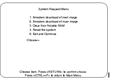
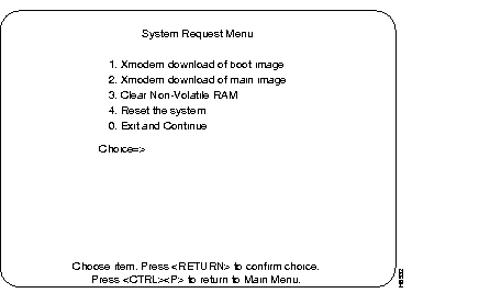
The following menu is displayed:

The following text is displayed:
SysReq: Beginning Xmodem download of boot image.
SysReq: Waiting for binary file...
~c (tilde and lowercase 'c')
This will give you a [cd] prompt. Enter the proper path to the directory containing the boot image. press carriage return.
SysReq: Waiting for binary file...
~C (tilde and uppercase 'C')
The following string should appear on the screen:
~CLocal command?
sx C3KBOOT.IMA (or the proper name of the boot image)
The system will download the specified image and will reboot automatically when finished.

SysReq: Beginning Xmodem download of boot image.
SysReq: Waiting for binary file...
~CLocal command?
sx epsboot.ima
Sending C3KBOOT.IMA, 443 XMODEM blocks.
Give your local XMODEM receive command now.
Sector xx xk
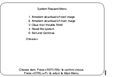
After all the boot image sectors have been downloaded, the following menu is displayed:

SysReq: Beginning Xmodem download of boot image.
SysReq: Waiting for binary file...
~CLocal command?
sx epsboot.ima
Sending C3KBOOT.IMA, 443 XMODEM blocks.
Give your local XMODEM receive command now.
Sector 442 55k away for 31 seconds!
Done. (located at 30010000)
SysReq: Overlaying old boot image and rebooting...
Cisco Catalyst Boot Firmware P/N 57-1327-02, Copyright 1995
- Initiating bootstrapping sequence.
- Boot image integrity check...Passed.
- Control transferred to boot process.
Boot Firmware (Phase II) v2.0
- Relocating main image to DRAM..................Done.
- Main image integrity check...succeeded.
- Control transferred to main process.
System Software Version 2.0(3), Copyright 1994-1996.
System started on Xxx. Xxx x, xxxx xx:xx:xx
8 Megabytes System memory
2 Megabytes Network memory
- Initialization started
- File system initialized
- System temperature is within safe operating levels
- Checking file system integrity
- Warmboot initialization started
- LAN ports detected:
- 10Base-T: 1 2 3 4 5 6 7 8 9 10 11 12 13 14 15 16
- StkPort : 25
- CPU Network memory test...
- CPU Network memory test...Passed
- Initializing Ports: 1 2 3 4 5 6 7 8 9 10 11 12 13 14 15 16 25
- Initializing system address table
- System entering stand-alone mode
- System initialization complete
- Starting SNMPv1 agent task
- Enabling port: 1 2 3 4 5 6 7 8 9 10 11 12 13 14 15 16 25
Press RETURN key to activate console...
The new bootcode will support all previous versions of the main image, including 9.0, 9.1, 1.1.3, and 1.3. It is recommended that you upgrade the bootcode on all the systems, even if you are not planning to upgrade them to 2.0(3) immediately, since the problem with the pre 2.0 version of the bootcode will continue to occur with all future releases (2.1, 2.2, etc.).
The following sections explain how to preserve an existing VTP/VLAN configuration.
As dictated by the VTP specification, the configuration of ports onto old EtherSwitch domains is now constrained by VTP as long the switch is participating in VTP (that is, as long as it isn't in VTP Transparent mode). This means that a local port cannot be assigned to any VLAN which is not configured via VTP. Thus, what used to be called Domain Port Configuration is now essentially VTP VLAN Configuration and the selections available to the user now consist of those defined in VTP rather than the switch's constant 64 choices. When a VTP VLAN is deleted and removed from the database for the administrative domain, all local ports assigned to it automatically become unassigned. An unassigned port does not belong to any VLAN and does not forward packets.
Besides local ports, IP, SNMP, Spanning Tree, and TFTP choices which were previously dependent upon the old domain context are now dependent on the VTP VLAN context. For instance, an IP address configured for the switch is now defined in a VTP VLAN and only applies to IP packets received on that VLAN, whether over a trunk or a local port. When a VTP VLAN is deleted all such parameters are permanently lost. If you don't want to lose the old parameters, you have the option of using the following procedures to reconfigure your switch after you download the 2.0(3) Software Release
With the 2.0 (and subsequent releases) the VTP and VLAN configuration replaces the current domain configuration. After the switch software reads the pre-2.0 configuration database, the new release code modifies the pre-2.0 configuration to create a new 2.0 (or above) configuration (VTP) database.
This database places the local Stack in VTP Transparent mode in order to give you the opportunity to complete the necessary manual steps of the upgrade procedure. In Transparent mode, all VTP configuration propagation packets are transparently forwarded to other trunks and are not used for local configuration. Until the Stack leaves Transparent Mode, all VLAN configuration is entirely under local control.
The initial VTP database will contain 68 VLANs: 64 Ethernet VLANs which are created to represent the 64 pre-2.0 Virtual EtherSwitches (what were formerly called Domains in some places) and the four VTP-mandatory non-Ethernet default VLANs which exist in all VTP databases.
The first of the 64 Ethernet VLANs corresponds to the VTP-mandatory default Ethernet VLAN and also to the pre-2.0 default Virtual EtherSwitch. The names of the other Ethernet VTP VLANs should correspond to the names of the Virtual EtherSwitches they replaced. Ports should be assigned to VLANs corresponding to the Virtual EtherSwitch to which they had previously been assigned.
IP, Spanning Tree, SNMP, and TFTP configuration parameters which had previously specified a Virtual EtherSwitch(es) now specify the corresponding VLAN(s)
In order to integrate into a VTP-controlled VLAN database environment, it is necessary to leave Transparent Mode and allow the global VTP database to overwrite the local one.
Before you do this, it is important to understand the consequences of this so you can take the necessary steps to prepare the local configuration.
When a device receives a new VTP database which supersedes its existing one, it implements the new database locally as appropriate. If new VLANs (as identified by their VLAN id number) are defined in the new database, then they are created locally. This allows the assignment of local ports to these new VLANs.
Regardless of whether the local device has begun running VTP or not, the trunk mapping of VLANs will occur as specified in the VTP database using VLAN id for ISL trunks and VLAN name for LANE trunks. Whether or not this mapping is appropriate for your configuration depends on which ports on a local Stack need to be members of the same VLAN (with other local assigned ports that exist on remote devices across the trunk and beyond).
To insure that the local VLAN port and parameter assignments resolve correctly and do not get deleted (once they are controlled by VTP):
For example, after the upgrade procedure, Virtual EtherSwitch 5, named Engineering, with five ports and an IP address of 192.5.5.5, will be changed to VLAN Engineering VTP id number 5 with the same port/IP assignments.
If you need to move VLAN Engineering from VTP id number 5 to another global VLAN with different VTP id number, follow the instructions in the Moving Local VLAN Assignments section.
If, in the example in the previous section, the user determines that the ports and address in local VLAN 5 need to be assigned to global VLAN 281 (because this will allow desired connectivity to other ports in global VLAN 281) the VLAN will need to be moved.
First of all, VLAN 281 needs to exist in order to move ports and parameters there. (The VLANs corresponding to the pre-2.0 database created are assigned id numbers 1 through 64 and the mandatory non-ethernet default VLANs are assigned id numbers 1002 through 1005.)
Step 1 The VLAN 281 must be created using the VTP VLAN Configuration Sub-menu (under the VLAN and VTP Configuration Menu.) If integration into the global database is imminent, there is no need to be concerned with most of the VTP parameters assigned to VLAN 281 in the local database since these will ultimately be overwritten by the global database. However, since there is a limit of 68 VLANs on a local device, one of the existing VLANs will need to be deleted to make room for VLAN 281. Use the delete function in this menu to remove a VLAN that is not needed.
Step 2 Add VLAN 281 using the Add function in the VTP VLAN Configuration menu. The parameters that need to be configured are:
The last two values will default as desired (Ethernet type/1500 MTU) when using this function in the VTP VLAN Parameter Configuration Menu. (As covered in a later section, the new VLAN need not and probably should not be made Preferred in the Local Preferred VLANs Configuration menu.)
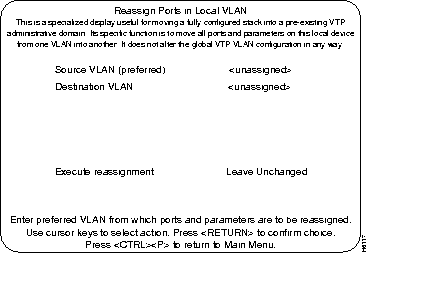
Step 3 Once VLAN 281 is created, ports and local parameters may be moved from VLAN 5 to VLAN 281. To move a local VLAN in a single step, use the Reassign Ports in Local VLAN sub-menu under the VLAN and VTP Configuration menu.
Step 4 The Reassign Ports in Local VLAN menu has four selectable items:
Step 5 In this example, the source VLAN would be VLAN 5 and the destination VLAN would be VLAN 281. Select the Execute Reassignment function to complete the move. Check that all local static ports and parameters have been moved from VLAN 5 to VLAN 281.
After all local VLAN moves have been executed and the local VLAN configuration appears correct, integrate this information into the global VTP environment. This procedure must be performed carefully since it may have a drastic effect on local configuration. Use the following steps for this procedure:
Step 1 Do a TFTP save of the configuration database. To do this, go to the Downloads/Upload menu and the TFTP Download/Upload sub-menu.
Step 2 To allow access to the system from the outside, go to the VTP Administrative Configuration menu.
Step 3 Set the Local Mode parameter to either Server or Client mode. If the global VTP database contains no secret value (password) and assuming the local environment has only one VTP administrative domain, this is the only necessary procedure you need to do. However, if you have set a secret value, it also will need to be set in the VTP Administrative Configuration menu
The local device learns the administrative domain name from the first peer to subsequently advertise it to the rest.
Step 4 If necessary, the local mode may be reset to Transparent mode and the configuration uploaded back into the device. Do not simply reload the configuration database without resetting the local VTP mode.
Step 5 After a period of time (normally not exceeding five minutes), the global VTP configuration should be received over the default Ethernet VLAN of any ISL or LANE trunk from a VTP peer (not itself in Transparent mode).
Step 6 The local VTP configuration should now be identical to the global one. If the VLAN moves have been done correctly all the ports and parameters should be assigned as desired and connected to ports in remote devices on their corresponding VLANs.
A preferred VLAN is a VLAN that contains configuration parameters such as IP/port assignments. A non-preferred VLAN does not have any local configuration parameters.
The source of a local VLAN move must be a preferred VLAN. This is because only preferred VLANs contain local port and (non-default) parameter assignments.
It is preferable to have the destination of a VLAN move be a non-preferred VLAN with no locally configured parameters.
However, if the destination VLAN of the move has configured values, you can perform one of the following actions:
A further selection on the VLAN and VTP Configuration menu will allow you to choose which of the two VLAN's local IP and Spanning Tree parameters are kept (assigned to the destination VLAN) and which are discarded.
This display is used to move a fully configured Stack into a pre-existing VTP administrative domain.

The following database (Table 1) assumes you would like to integrate the ports on the VLANs named local-(appropriate name) on the Stack being upgraded to 2.0 (3), using VTP, into the correspond global VLANs name global-(appropriate name). For instance, it is desired that ports 2, 4, and 8 (which originally belonged to local-W on the local Stack will ultimately become members of the VLAN named global-W.
| Local VTP Database | Global VTP Database | |||
|---|---|---|---|---|
| VLAN ID # | VLAN Name | Ports | VLAN ID# | VLAN Name |
| 1 | default | 1, 3, 15 | 1 | default |
| 2 | local-w | 2, 4, 8 | 2 | global-A |
| 3 | local-x | 5, 10, 16 | 3 | global-B |
| 4 | local-y | 6, 12, 14 | 4 | global-C |
| 5 | local-z | 7, 9, 11, 13 | 5 | global-W |
| 6 | VLAN 5 | 6 | global-D | |
| 7 | VLAN 6 | 8 | global-E | |
| 8 | VLAN 7 | 12 | global-X | |
| 9 | VLAN 8 | 25 | global-F | |
| 10 | VLAN 9 | 67 | global-Y | |
| 11 | VLAN 10 | 281 | global-Z | |
| . | ||||
| . | ||||
| . | ||||
| . | ||||
| 64 | VLAN 63 | |||
As an alternative, you could swap VLANs 2 and 5 first, thus moving the ports and parameters of local-z to local-w and vice versa. (Note that the names do not move.) Then move VLAN 2 to VLAN 281.
After this has been done (and sufficient time has passed such the configuration has propagated from a neighboring device or Stack running VTP), the Local database should go away completely and the user will see the Global database implemented on the upgraded Stack. All the ports and parameters should have survived the move, however, and will be found in the VLANs they were assigned to by VLAN id number before the mode was changed.
For service and support for a product purchased from a reseller, contact the reseller. Resellers offer a wide variety of Cisco service and support programs, which are described in the section "Service and Support" in the information packet that shipped with your chassis.
For service and support for a product purchased directly from Cisco, use CCO.
CCO is Cisco Systems' primary, real-time support channel. SMARTnet customers and partners can self-register on CCO to obtain additional content and services.
Available 24 hours a day, 7 days a week, CCO provides a wealth of standard and value-added services to Cisco's customers and business partners. CCO services include product information, software updates, release notes, technical tips, the Bug Navigator, configuration notes, brochures, descriptions of service offerings, and download access to public and authorized files.
CCO serves a wide variety of users through two interfaces that are updated and enhanced simultaneously--a character-based version and a multimedia version that resides on the World Wide Web (WWW). The character-based CCO supports Zmodem, Kermit, Xmodem, FTP, and Internet e-mail, and is excellent for quick access to information over lower bandwidths. The WWW version of CCO provides richly formatted documents with photographs, figures, graphics, and video, as well as hyperlinks to related information.
You can access CCO in the following ways:
For a copy of CCO's Frequently Asked Questions (FAQ), contact cco-help@cisco.com. For additional information, contact cco-team@cisco.com.
Please use CCO to obtain general information about Cisco Systems, Cisco products, or upgrades. If CCO is not accessible, contact 800 553-6387, 408 526-7208, or cs-rep@cisco.com.

|
|