|
|

This configuration note provides the following information:
You can install a Catalyst Matrix module in either the left hand, right hand, or both positions of the Catalyst Matrix chassis. If a module fails, you can easily replace it. The only tool needed is a Phillips or cross-headed screwdriver. The following procedure describes how to add or replace a Catalyst Matrix module.
Use the following steps for installing or replacing a Catalyst Matrix module. If you are installing a module into an open slot, proceed to Step 5.
Step 1 If there is a blank cover plate, remove the screw located at the top center and then remove the plate. (Reverse the procedure to install a cover plate.)
Step 2 If removing a module, switch it off line and disconnect power from the module. (See previous note pertaining to power to the module.)
Step 3 Remove the screw located at the top center of the front of the module.
Step 4 Using the handle on the front of the module, pull the module straight out from the chassis.
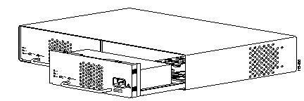
Step 5 Insert the module into the open slot. In Figure 1, the secondary module is being inserted into the unit. Place the bottom of the module against the bottom of the slot and slide the module into the slot. You should feel some resistance as the module connector mates with the Matrix connector. If you feel solid resistance, pull the module back a little and try again while moving the module slightly to the left or right until you feel the two connectors engage. After the connectors start to engage, you should be able to insert the module approximately one-half inch further and then you should feel hard resistance. The connectors should be seated at that point.
Step 6 Install the screw at the top center of the module's front plate.
Step 7 Connect the power cord to the module.
Step 8 To bring this module on line, press the ACTIVATE push-button.
The following section explains the installation and use of the Catalyst Stack Port connection module, which enables two or more Catalyst 3000 units to work together as a stack.
The Catalyst Stack Port is a single-port expansion module with a special 50-pin connector. If you have two Catalyst 3000 units each equipped with a Catalyst Stack Port module, when you connect the modules the two Catalyst 3000 units, can function as a stack. If you have more than two Catalyst 3000 units each equipped with a Catalyst Stack Port module, you can combine them into a unified Catalyst Stack by connecting each module to a Catalyst Matrix unit. See the section "Connecting Catalyst 3000 Units to the Catalyst Matrix" in the "Catalyst 3000 and Catalyst Stack User Guide." The Catalyst Matrix supports a stack of up to eight Catalyst 3000 units.
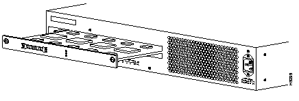
The module can be inserted in its expansion slot as shown in Figure 2.
 | Caution Catalyst Stack Port modules are not hot-swappable. Always be sure that the power is off before installing or removing a Catalyst Stack Port module. If the power is on, damage to the equipment may result. |
| **before**Do not touch the components or connectors on the Catalyst Stack Port module. Do not touch cable connector pins when the other end is plugged in. Damage may result from static discharge.@@before@@ | Caution **after**Do not touch the components or connectors on the Catalyst Stack Port module. Do not touch cable connector pins when the other end is plugged in. Damage may result from static discharge.@@after@@ |
| **before**During installation, the connector on the Catalyst Stack Port module must line up evenly with the connector inside the expansion slot. Misalignment may cause the connector pins to bend. When inserting the Catalyst Stack Port module into the expansion slot, be sure that the board is level and that the left and right sides slide evenly into the slot.@@before@@ | Caution **after**During installation, the connector on the Catalyst Stack Port module must line up evenly with the connector inside the expansion slot. Misalignment may cause the connector pins to bend. When inserting the Catalyst Stack Port module into the expansion slot, be sure that the board is level and that the left and right sides slide evenly into the slot.@@after@@ |
Use the following steps when installing a Catalyst Stack Port module into the rear expansion slot of the Catalyst 3000 chassis.
Step 1 Disconnect the power to the Catalyst 3000.
Step 2 If a blank cover is over the Catalyst Stack Port module slot, remove it by unscrewing its two attachment screws.
Step 3 To prevent possible static damage to the module, hold it by its edges only. Be careful not to touch the top or bottom.
Step 4 Slide the module into the slot evenly, taking care to line up the edges with the guides.
Step 5 Seat the module by pressing the front of the module with your thumbs.
Step 6 Secure the module to the chassis by tightening the thumb (panel) screws at the left and right edges of the expansion modules front panel. Do not overtighten the screws.
Step 7 Return power to the switch.
The Catalyst Stack Port module has a 50-pin SCSI-2 connector designed to accept stack-port cables. Do not attempt to use a SCSI-2cable, for more information about these cables, contact the Cisco Technical Assistance Center (TAC).
The 100BaseTX and 100BaseF expansion modules are explained in the following sections.
 | Caution Expansion modules are not hot-swappable. Always be sure that the power is off before installing or removing an expansion module. If the power is on, damage to the equipment may result. |
The WS-X3001 is a single-port 100BaseTX expansion module. Use the 100BaseTX to connect to computers, hubs, servers, and other high-speed network devices. The following sections explain the installation, cable connection, and network connection for the 100BaseTX expansion module. For a functional description of the 100BaseTX and the Catalyst 3000, see Chapter 2, "Catalyst 3000 Theory of Operation," in the Catalyst 3000 and Catalyst Stack User Guide.
The 100BaseTX expansion module is shown in Figure 3.

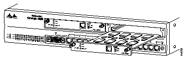
The modules can be inserted in either of the two expansion slots, as shown in Figure 4.
Use the following steps when installing a 100BaseTX module into an expansion slot of the Catalyst 3000 chassis.
 | Caution Do not touch the components or connectors on the expansion module. Do not touch cable connector pins when the other end is plugged in. Damage may result from static discharge. |
| **before**During installation, the connector on the expansion module must line up evenly with the connector inside the expansion slot. Misalignment may cause the connector pins to bend. When inserting the module into the expansion slot, be sure that the board is level and that the left and right sides slide evenly into the slot.@@before@@ | Caution **after**During installation, the connector on the expansion module must line up evenly with the connector inside the expansion slot. Misalignment may cause the connector pins to bend. When inserting the module into the expansion slot, be sure that the board is level and that the left and right sides slide evenly into the slot.@@after@@ |
Step 1 Disconnect the power to the Catalyst 3000.
Step 2 If a blank cover is over the expansion module slot, remove it by unscrewing the two attachment screws.
Step 3 To prevent possible static damage to the module, hold it by its edges only. Be careful not to touch the top or bottom.
Step 4 Slide the module into the slot evenly, taking care to line up the edges with the guides.
Step 5 Seat the module by pressing the front of the module with your thumbs.
Step 6 Secure the module to the chassis by tightening the thumb (panel) screws at the left and right edges of the expansion modules front panel. Do not overtighten the screws.
Step 7 Return power to the switch.
The 100BaseTX module's network port is an RJ-45 connector that uses 100BaseTX cable.
The 100BaseTX module's network port is an RJ-45, 100BaseTX type that is always in MDI-X mode. Cabling the 100BaseTX to different types of equipment that have MDI or MDI-X ports will require different types of 100BaseTX cable. The cable types are described below.
Use the 10BaseT cable information in Appendix A, of the Catalyst 3000 and Catalyst Stack User Guide, as a reference for 100BaseTX cable.
Connect cables to the RJ-45 port on the front of the 100BaseTX module as follows:
Step 1 Half/full-duplex mode. If the Catalyst 3000 is an enhanced version, see the section "Configuring Full-Duplex Communications" in the Catalyst 3000 and Catalyst Stack User Guide for a detailed explanation on how to determine whether the communication mode will be half- or full-duplex. The Catalyst 3000 and the 100BaseTX will operate in half-duplex mode only for non-enhanced Catalyst 3000 units. Set the DUPLEX switch on the front of the module to the appropriate position: down for half-duplex, or up for full-duplex. Set to half-duplex only for non-enhanced Catalyst 3000 units.
Step 2 Determine that you have the correct cable. See "Appendix A" in the Catalyst 3000 and Catalyst Stack User Guide for a description of 100BaseTX cables.
Step 3 Connect a 100BaseTX cable from a hub or end-node device to the RJ-45 jack on the front of the expansion module.
Step 4 Insert the cable's 8-pin (RJ-45) plug into the jack until it clicks into place.
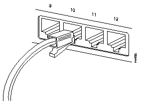
When the connection is established, the LNK/FDX LED is on: green in half-duplex mode, or yellow in full-duplex mode. If the LED is not on, there may be a cable problem. Verify that you are using the correct type of cable, then check if the cable is bad by trying a different one.
If, after installation, there is poor system performance or the 100BaseTX module does not work at all, remove the module and check for any damage or bent connector pins. You may need a bright light to see inside the expansion module slot to check for bent pins. Also, verify that the module is set firmly in place. If you cannot find an immediate cause for the problem, refer to Chapter 11, "Troubleshooting," in the 7Catalyst 3000 and Catalyst Stack User Guide.
The following tables describe the connectors, LEDs, and switches on the 100BaseTX module.
| Name | Description |
| Network Port | 8-pin, RJ-45, 100BaseTX |
| Name | Description |
| XMIT | A packet has been transmitted to the attached segment. |
| RCV | A packet has been received from the attached segment. |
| LNK/FDX | Off = link not detected.
Green = half-duplex, Yellow = full-duplex (Enhanced version only). |
| DIAG | Running diagnostic. In normal operation DIAG should be off. |
| Name | Description |
| Duplex | Establishes the communication mode of the network port if the Catalyst 3000 is an enhanced version. Only set to half-duplex for non-enhanced versions.
Full-duplex (up) or half-duplex (down). |
The 100BaseF expansion module (WS-X3005) is a single-port 100BaseFx expansion module. Use this module for high-bandwidth fiber-optic connections to computers, hubs, servers, and other high-speed network devices. The 100BaseF expansion module is shown in Figure 6.

Expansion modules can be inserted in either of the two expansion slots on the front of the unit. To install the 100BaseF module into the unit, refer to Figure 4, which illustrates insertion of a 100BaseTX module into the right slot.
To install a 100BaseF module into an expansion slot of the Catalyst 3000 chassis use the following steps:
 | Caution Do not touch the components or connectors on the expansion module. Damage may result from static discharge. |
| **before**During installation, the connector on the expansion module must line up evenly with the connector inside the expansion slot. Misalignment may cause the connector pins to bend. When inserting the module into the expansion slot, be sure that the board is level and that the left and right sides slide evenly into the slot.@@before@@ | Caution **after**During installation, the connector on the expansion module must line up evenly with the connector inside the expansion slot. Misalignment may cause the connector pins to bend. When inserting the module into the expansion slot, be sure that the board is level and that the left and right sides slide evenly into the slot.@@after@@ |
Step 1 Disconnect power to the Catalyst 3000.
Step 2 Remove the cover (if there is a blank cover over the expansion module slot) by unscrewing the two attachment screws.
Step 3 Hold the module by the edges to prevent static damage. Be careful not to touch the top or bottom.
Step 4 Slide the module into the slot evenly, taking care to line up the edges with the guides.
Step 5 Seat the module by pressing the front of the module with your thumbs.
Step 6 Secure the module to the chassis by tightening the thumb (panel) screws at the left and right edges of the expansion modules front panel. Do not overtighten the screws.
Step 7 Return power to the switch.
The 100BaseF module's network port is a 1300 nm multi-mode fiber-optic interface with ST-style connectors.
Enhanced versions of the Catalyst 3000 support full-duplex operating mode. Non-enhanced versions of the Catalyst supports only half-duplex operating mode. If the Catalyst 3000 in which the 100BaseF is being installed is an enhanced version, refer to the section "Full-Duplex Configuration (Enhanced Models only)" in the Catalyst 3000 and Catalyst Stack User Guide. That section explains how to determine whether the communication mode used will be half-duplex or full-duplex.
In full-duplex operating mode, the 100BaseF supports connection distances up to 2 km. In half-duplex operating mode, the 100BaseF supports connection distances up to 450 m.
Connect cables to the ST ports on the front of the 100BaseF module as follows:
Step 1 Half/full-duplex mode. The Catalyst 3000 and the 100BaseF only operates in half-duplex mode for non-enhanced Catalyst 3000 units. Set the DUPLEX switch on the front of the module to the appropriate position: down for half-duplex, or up for full-duplex. Set to half-duplex for non-enhanced Catalyst 3000 units.
Step 2 Determine that you have the correct cable. See "Appendix A" in your Catalyst 300 and Catalyst Stack User Guide for a description of 100BaseFx cables.
Step 3 Connect a 100BaseFx cable from a hub or end-node device to the ST ports on the front of the expansion module.

|
|