|
|

To alter the configuration of your Catalyst 3920, follow these steps:
Step 1 If one has not already been established, establish a console session. For information about establishing a console session, refer to the "Planning for Configuration and Management" chapter.
Step 2 At the Main Menu, select Configuration. The Configuration Menu panel (Figure 5-1) is displayed.
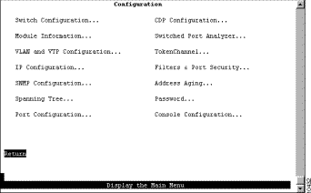
Step 3 Select the menu option you want.
Step 4 Change or enter values.
Step 5 When you have changed or entered all of the required configuration parameters, save the changes and return to the Cisco Catalyst 3920 Main Menu. Configuration is complete.
As you move through the console panels, follow these guidelines:
1-3 5 7-9
1-3,5,7-9
To view or change basic switch and stack information, such as the system name, system location, or system contact, select Switch Configuration on the Configuration Menu. The Switch Configuration panel (Figure 5-2) is displayed.

The following information is displayed on this panel:
| To | Select | Then |
|---|---|---|
Change the current settings... | The appropriate parameter... | Specify the new value. |
View additional information about the switch... | Stack Configuration | Refer to the "Configuring Stack Parameters" section. |
Save your changes... | Return |
|
To configure stack parameters, select Stack Configuration on the Switch Configuration panel. The Stack Configuration panel (Figure 5-3) is displayed.

The following information is displayed on this panel:
To view general information about the Catalyst 3920 and the stack port, select Module Information on the Configuration Menu. The Module Information panel (Figure 5-4) is displayed.
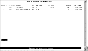
The following information is displayed on this panel:
You cannot change the information that appears on this panel.
You can partition a single Catalyst 3920 into multiple VLANs. A VLAN can be configured with its own IP address and managed with SNMP. A VLAN can contain ports from multiple switches in the same stack. Any VLAN can participate independently in the Spanning-Tree Protocol (STP). Once VLANs have been established, packets are forwarded between ports belonging to the same VLAN only.
You can use the VLAN Trunking Protocol (VTP) to set up and manage VLANs across an entire administrative domain. When new VLANs are added to a Catalyst switch in an administrative domain, VTP can be used to automatically distribute the information to the trunk ports of all the devices in the administrative domain. This allows VLAN naming consistency and connectivity between all devices in the administrative domain.
An administrative or management domain is a logical grouping of VLANs used by the VTP for the purpose of administration and management. VTP parameters are propagated throughout the VLANs within a single management domain. While you can have duplicate VLAN names in a network, each VLAN name within a management domain must be unique. A management domain is not device specific. Different devices may belong to the same management domain if the VLANs defined for the devices belong to the same management domain. Likewise, a device may belong to multiple management domains if the VLANs defined for the device belong to different management domains.
For more information about Token Ring VLANs, refer to the "Token Ring VLANs" section of the "Understanding Token Ring Switching" appendix.
To configure VLANs and the VTP for the Catalyst 3920, select VLAN and VTP Configuration on the Configuration Menu. The VLAN and VTP Configuration panel (Figure 5-5) is displayed.
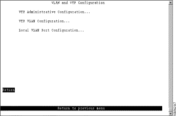
The following options are displayed on this panel:
To view parameters for the VTP, select VTP Administrative Configuration on the VLAN and VTP Configuration panel. The VTP Administrative Configuration panel (Figure 5-6) is displayed.
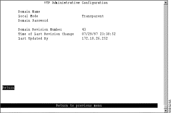
The following information is displayed on this panel:
You can define VLANs for the entire network from a single switch. The VLAN configuration is propagated to all switches in the same administrative domain using the VTP advertisement protocol. To define VLANs, select VTP VLAN Configuration on the VLAN and VTP Configuration panel. The VTP VLAN Configuration panel (Figure 5-7) is displayed. The panel lists the VLANs with respect to their parent-child relationships. Each TrBRF is followed by an indented list of the TrCRFs for which it is a parent. You can also sort the entries on the panel by VLAN ID. This is particularly useful when you are searching for a particular VLAN or when you want to add a VLAN and need to see the IDs that have already been assigned.

The following information is displayed on this panel:
| To | Select | Then |
|---|---|---|
View the current configuration of a VLAN, including a list of associated ports for a TrCRF... | View | Specify the VLAN ID. |
Add a new TrBRF VLAN configuration... | Add | Specify the VLAN ID. Select TrBRF. Refer to the "Adding or Changing TrBRF VLAN Parameters" section. |
Add a new TrCRF VLAN configuration... | Add | Specify the VLAN ID. Select TrCRF. Refer to the "Adding or Changing TrCRF VLAN Parameters" section. |
Change an existing TrBRF VLAN configuration... | Change | Specify the VLAN ID and refer to the "Adding or Changing TrBRF VLAN Parameters" section. |
Change an existing TrCRF VLAN configuration... | Change | Specify the VLAN ID and refer to the "Adding or Changing TrCRF VLAN Parameters" section. |
Add or remove a TrBRF or TrCRF from the list of preferred VLANS... | Change_Local_State | Specify the VLAN ID and confirm your request to add or remove the VLAN from the preferred list. Then, press any key to refresh the panel. |
Delete a VLAN... | Delete | Specify the VLAN ID. |
Display a list of VLANs sorted by VLAN ID... | Sort | Select Sort_by_VLAN_ID. |
Save your changes... | Return |
|
To add a new TrBRF, select Add on the VTP VLAN Configuration panel, enter the VLAN ID (2 through 1001) and select TrBRF. To change the definition of an existing TrBRF, select Change on the VTP VLAN Configuration panel and specify the VLAN ID. In either case, the VLAN Parameter Configuration for TrBRF panel (Figure 5-8) is displayed.
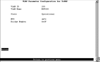
The following information is displayed on this panel:
To add a new TrCRF, select Add on the VTP VLAN Configuration panel, enter the VLAN ID (2 through 1001) and select TrCRF. To change the definition of an existing TrCRF, select Change on the VTP VLAN Configuration panel and specify the VLAN ID. In either case, the VLAN Parameter Configuration for TrCRF panel (Figure 5-9) is displayed.
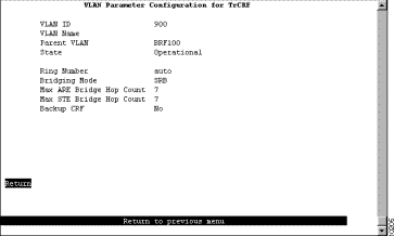
The following information is displayed on this panel:
 | Caution If the ports of the TrCRF VLAN are connected to a ring that contains only workstations, the port will be unable to learn the ring number. In this case, you must configure the ring number. |
To change the definition of the default Ethernet VLAN, select Change on the VTP VLAN Configuration panel and specify the VLAN ID. The VLAN Parameter Configuration for Ethernet panel (Figure 5-10) is displayed. You can change the values of the security association identifier, MTU, and the translationally bridged VLANs only.
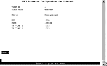
The following information is displayed on this panel:
Although you cannot configure or modify a FDDI and FDDI-Net VLAN from the Catalyst 3900, you can view the definitions of FDDI and FDDI-Net VLANs that exist in your VTP administrative domain.
To view the definition of an existing FDDI or FDDI-Net VLAN, select View on the VTP VLAN Configuration panel and specify the VLAN ID. The VLAN Parameter Configuration for FDDI (or the VLAN Parameter Configuration for FDDI-Net) panel (Figure 5-11) is displayed.
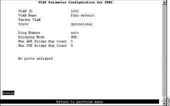
The following information is displayed on this panel:
If the VLAN type is FDDI, the following additional information is displayed for FDDI VLANs:
If the VLAN type is FDDI-Net, the following additional information is displayed for FDDI-Net VLANs:
To display a list of the VLAN port assignments, select Local VLAN Port Configuration on the VLAN and VTP Configuration panel. The Local VLAN Port Configuration panel (Figure 5-12) is displayed.
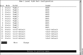
This panel displays the following information about the VLAN port assignments:
| To | Select | Then |
|---|---|---|
Change the TrCRF to which the port is assigned... | Change | Select the VLAN from the displayed list of TrCRFs. |
Save your changes... | Return |
|
To view or change IP information associated with a TrBRF, such as the IP address, subnet mask, or IP state, or to send PINGs, select IP Configuration on the Configuration Menu. The IP information that you can configure is associated with a TrBRF. Therefore, if the ports of the Catalyst 3920 are assigned to more than one TrBRF, when you select IP configuration you will be presented with a list of possible TrBRFs from which to choose. The IP Configuration panel (Figure 5-13) is displayed.
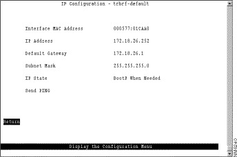
The following information is displayed on this panel:
When you select either of the BootP options for the IP state, the Catalyst 3920 repeats BootP requests at regular intervals, beginning at 1 second intervals and eventually decreasing to 5 minute intervals until it has received a valid response.
The following BootP response parameters are recognized and recorded in NVRAM:
The BootP requests will also cease if a valid IP address is configured via the console panels or if the IP state is set to IP Disabled. Once the Catalyst 3920 stops sending BootP requests on a domain, it does not resume sending requests or recognize BootP responses on that domain unless the Catalyst 3920 is reset.
For more information about BootP, refer to the "Understanding BootP" appendix.
| To | Select | Then |
|---|---|---|
Change the current settings... | The appropriate parameter... | Specify the value. |
Verify the network availability of a particular resource... | Specify the IP address of the resource. | |
Save your changes... | Return |
|
To allow the Catalyst 3920 to be managed by an SNMP manager, you must first configure the SNMP parameters. To view or set SNMP parameters, such as the community names, where traps are to be sent, and whether authentication failure traps should be sent, select SNMP Configuration on the Configuration Menu. The SNMP Configuration panel (Figure 5-14) is displayed.
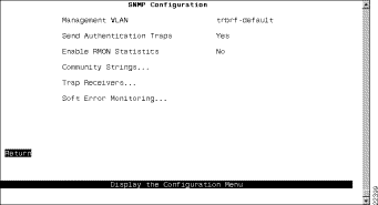
The following information is displayed on this panel:
| To | Select | Then |
|---|---|---|
Change the current settings | The appropriate parameter | Specify the value. |
View or change SNMP community names and privileges | Community Strings | Refer to the "Specifying Community Names" section. |
View or change which SNMP managers are to receive traps for which domains | Trap Receivers | Refer to the "Specifying Trap Receivers" section. |
View or change the soft error monitoring configuration for the ports on the switch... | Soft Error Monitoring | Refer to the "Configuring Soft Error Monitoring" section. |
Save your changes | Return |
|
A community name is a password that a set of SNMP managers use to manage a specified device. Each community name is associated with a specific privilege level of management. To view or change the community names for the domains of the Catalyst 3920, select Community Strings on the SNMP Configuration panel. The Community Strings panel (Figure 5-15) is displayed.
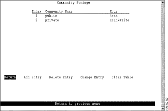
The following information is displayed on this panel:
Entries are displayed in the order in which they are entered. Only five community names can be entered.
| To | Select | Then |
|---|---|---|
Add a community name | Add Entry | Specify the community name and privilege. |
Delete a community name | Delete Entry | Specify the name to be deleted. |
Change a community name or privilege | Change Entry | Specify the index number of the entry to be changed and enter the new information. |
Delete all community names | Clear Table |
|
Save your changes | Return |
|
To view or change the list of SNMP managers to which traps are sent, select Trap Receivers on the SNMP Configuration panel. The Trap Receivers panel (Figure 5-16) is displayed.
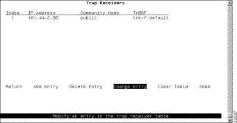
The following information is displayed on this panel:
The trap receivers list can contain a maximum of 10 entries.
The SNMP Trap Receivers information that you can configure is associated with a TrBRF. Therefore, if the ports of the Catalyst 3920 are assigned to more than one TrBRF and you select Add Entry or Change Entry on the Trap Receivers panel, after specifying the community name, you will be presented with a list of possible TrBRFs from which to choose.
| To | Select | Then |
|---|---|---|
Add an entry to the list | Add Entry | Specify the IP address, community name, and TrBRF. |
Delete an entry | Delete Entry | Specify the index number of the entry to be deleted. |
Change an entry in the list | Change Entry | Specify the index number of the entry to be changed and enter the new information. |
Delete all entries | Clear Table |
|
Display the complete list of TrBRFs assigned to an IP address | Zoom | Specify the index number. |
Save your changes | Return |
|
To view or change the soft error monitoring configuration for a port, select Soft Error Monitoring on the SNMP Configuration panel. The Soft Error Monitoring panel is displayed (Figure 5-17).
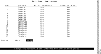
The following information is displayed on this panel:
| To | Select | Then |
|---|---|---|
Change the soft error monitoring configuration for a port or ports in the list | Change | Specify the port or port list to be changed and enter the new information as prompted. Enter the port, range of ports, or both and separate by spaces or commas. When entering a range of ports, enter the lowest port first and separate with a hyphen (for example, 8-16). To enter all ports on a switch, type an asterisk (*). |
Save your changes | Return |
|
For more information about spanning tree, refer to the "Spanning-Tree Protocol" section of the "Understanding Token Ring Switching" appendix.
To view or change the spanning-tree parameters associated with a VLAN, such as the switch priority and the port path cost, select Spanning Tree on the Configuration Menu and then select the desired TrBRF. The Spanning Tree for TrBRF panel (Figure 5-18) is displayed.
When you configure spanning-tree parameters for a TrBRF, you:
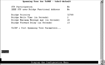
The following information is displayed on this panel:
| To | Select | Then |
|---|---|---|
Change the current settings | The appropriate parameter | Specify the value. |
View or change the spanning-tree parameters for one of the TrCRFs associated with this TrBRF | TrCRF & Port Spanning Tree Parameters | Refer to the "Changing Spanning-Tree Parameters for a TrCRF" section. |
Save your changes | Return |
|
To view or change the spanning-tree parameters for a TrCRF associated with the selected TrBRF, select TrCRF & Port Spanning Tree Parameters on the Spanning Tree panel and then select the desired TrCRF. The Spanning Tree for TrCRF panel (Figure 5-19) is displayed.
When you configure the spanning-tree parameters for a TrCRF, you:
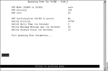
The following information is displayed on this panel:
| To | Select | Then |
|---|---|---|
Change the current settings | The appropriate parameter | Specify the value. |
View or change the spanning-tree parameters for the ports that belong to this TrCRF... | Port Spanning Tree Parameters | Refer to the "Changing Spanning-Tree Parameters for a Port" section. |
Save your changes | Return |
|
To view or change the priority, path cost, and spanning-tree mode of a port, select Port Spanning Tree Parameters on the Spanning Tree panel. The Port Spanning Tree Parameters panel (Figure 5-20) is displayed.
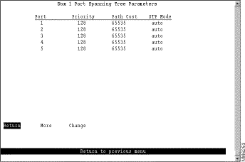
The following information is displayed on this panel:
| To | Select | Then |
|---|---|---|
Change a parameter associated with a port | Change | Specify the port number, select the appropriate parameter, and then specify the new value. |
Save your changes | Return |
|
To view or change the configuration parameters of a port such as the mode, type, and speed, select Port Configuration on the Configuration Menu and specify the port number. The Port Configuration panel (Figure 5-21) is displayed.
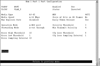
The following information is displayed on this panel:
| To | Select | Then |
|---|---|---|
Change the current settings... | The appropriate parameter... | Specify the new value. |
Save your changes | Return |
|
Each device configured for CDP sends periodic messages to a multicast address. Each device advertises at least one address at which it can receive SNMP messages. The advertisements also contain time-to-live, or holdtime, information, which indicates the length of time a receiving device should hold CDP information before discarding it.
To configure CDP parameters, select CDP Configuration on the Configuration Menu. The CDP Configuration panel (Figure 5-22) is displayed.
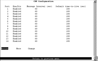
The following information is displayed on this panel:
| To | Select | Then |
|---|---|---|
Change a parameter associated with a port | Change | Specify the port number, select the appropriate parameter, and then specify the new value. |
Save your changes | Return |
|
An active port monitor allows you to use a customer-supplied trace tool, such as a Network General Sniffer, to monitor only the LLC traffic that is switched by the monitored port. The MAC frames are not monitored.
Configuring a port to be a SPAN port removes the port from the TrCRF to which it is currently assigned. If you then disable the SPAN port, or configure a new port to be the SPAN port, the port remains unassigned to a TrCRF until you reassign it to a TrCRF.
To be inserted into a ring, ports must be assigned to a TrCRF unless they are configured as a SPAN port. Therefore, ports that are not configured as SPAN ports and are unassigned will not be able to be inserted into the ring until you reassign them to a TrCRF or configure them as a SPAN port.
For information about how to assign a port to a TrCRF, refer to the "Displaying VLAN Port Assignments" section.
To configure a SPAN port, select Switched Port Analyzer on the Configuration Menu. The Switched Port Analyzer panel (Figure 5-23) is displayed.
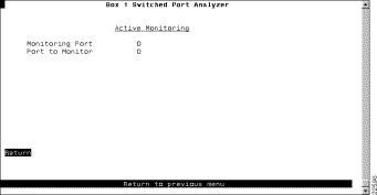
The following information is displayed on this panel:
| To | Select | Then |
|---|---|---|
Change the current settings | The appropriate parameter | Specify the value. |
Disable the SPAN port | Port to Monitor | Specify 0. |
Save your changes | Return |
|
To view or change the TokenChannel definitions, select TokenChannel on the Configuration Menu. The TokenChannel panel (Figure 5-24) is displayed.
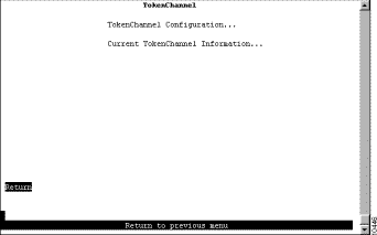
The following options are displayed on this panel:
To configure one or more TokenChannels, select TokenChannel Configuration on the TokenChannel panel. The TokenChannel Configuration panel (Figure 5-25) is displayed.
Using TokenChannels provides the following benefits:
A single TokenChannel can consist of a combination of HDX and FDX connections. For example, a TokenChannel consisting of three connections can have one HDX and two FDX connections. However, both ports in each interconnected pair must be either HDX or FDX. In addition, all ports in a single TokenChannel must belong to the same TrCRF on the Catalyst 3920.
 | Caution While you can use a TokenChannel to interconnect Catalyst 3900s and Catalyst 3920s, you cannot use a TokenChannel to interconnect other different models of switches. For example, you cannot use a TokenChannel to interconnect a Catalyst 2600 and a Catalyst 3900. Likewise, you cannot use a TokenChannel to interconnect a Catalyst 3900 and a non-Cisco switch. |
Catalyst 3920 TokenChannels are fault tolerant. This feature enables the TokenChannel to continue to function as long as there is at least one link active in the channel. This capability ensures that large portions of a network are not disrupted in the event a port or cable fails within the channel by transferring the traffic to one or more of the remaining ports in the channel. A TokenChannel displays in a reduced state when some, but not all of the ports assigned to the channel are up.
Before you configure a TokenChannel, be aware of the following guidelines:
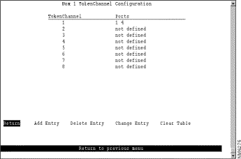
The following information is displayed on this panel:
| To | Select | Then |
|---|---|---|
Define a new TokenChannel | Add Entry | Specify the ports that compose the new TokenChannel, separated by spaces. You cannot specify more than 8 ports. |
Delete the definition for a TokenChannel | Delete Entry | Specify the identifier of the TokenChannel to be deleted. |
Change the definition of a TokenChannel | Change Entry | Specify the identifier of the TokenChannel to be changed and enter the new information. The ports associated with a TokenChannel must be disabled or disconnected before you change the TokenChannel definition. |
Delete all TokenChannel definitions | Clear Table | Confirm the deletion of all TokenChannel definitions. |
Save your changes | Return |
|
To view the configuration of currently defined TokenChannels, select Current TokenChannel Information on the TokenChannel panel. The Current TokenChannel Information panel (Figure 5-26) is displayed.
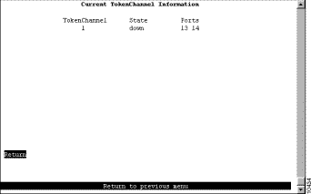
The following information is displayed on this panel:
To limit access, you can do the following:
To limit the scope and access of users on segments attached to the Catalyst 3920, select Filters & Port Security from the Configuration Menu. The Filters & Port Security panel (Figure 5-27) is displayed.
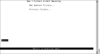
The following options are displayed on this panel:
To restrict certain users from communicating with other users or resources (such as printers or servers), select MAC Address Filters on the Filters & Port Security panel. The MAC Address Filters panel (Figure 5-28) is displayed.
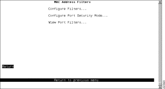
The following options are displayed on this panel:
To configure a new MAC address filter, select Configure Filters on the MAC Address Filters panel. The Configure Filters panel (Figure 5-29) is displayed.
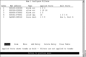
The following information is displayed on this panel:
You can define up to 250 source or destination MAC addresses to be filtered at the port of entry into the Catalyst 3920. MAC addresses can be unicast, multicast (group), or broadcast. All 250 addresses can be associated with one port or divided among the available ports.
| To | Select | Then |
|---|---|---|
Display the complete list of Entry Ports and Exit Ports for a filter | Zoom | Specify the index number. |
Add a filter | Add Entry | Specify the filter type, the MAC address, and the ports. The port numbers should be listed from lowest to highest and be separated by spaces. If you do not specify a port number, the filter will be applied to all ports. |
Delete a filter | Delete Entry | Specify the index number of the filter to be deleted. |
Delete all filters | Clear Table | Confirm the deletion of all filters. |
Save your changes | Return |
|
The Catalyst 3920 also allows you to totally block (secure) communication at selected ports, unless explicitly allowed by a MAC filter. Addresses that have been allowed or forced by a configured filter are not blocked. To define the security attributes of each port, select Configure Port Security Mode on the MAC Address Filters panel. The Configure Port Security Mode panel (Figure 5-30) is displayed.
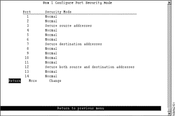
The following information is displayed on this panel:
| To | Select | Then |
|---|---|---|
Change the security mode for a port | Change | Specify the port and the desired security mode. |
Save your changes | Return |
|
To display the defined filters for a specific port, select View Port Filters on the Filters & Port Security panel and specify the port number. The View Port Filters panel (Figure 5-31) is displayed.
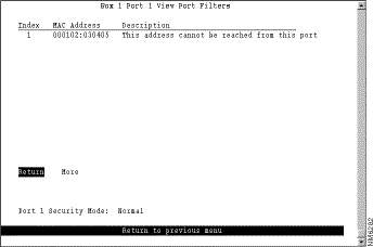
The following information is displayed on this panel:
You cannot change any information on this panel.
To filter data based on protocol, select Protocol Filters on the Filters & Port Security panel. The Protocol Filters panel (Figure 5-32) is displayed.
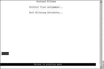
The following options are displayed on this panel:
To use protocol filtering, you must first define the protocol classes. You can define up to 15 protocol classes for use in protocol filtering. To define the protocol classes, select Protocol Class Assignment on the Protocol Filters panel. The Protocol Class Assignment panel (Figure 5-33) is displayed.
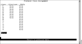
The following information is displayed on this panel:
| To | Select | Then |
|---|---|---|
Change the current settings | The appropriate port... | Specify the value. |
Save your changes | Return |
|
After you have defined your protocol classes, you can define how a port handles frames for each protocol class. To define how each class is handled, select Port Filtering Attributes on the Protocol Filters panel and specify the port number. The Port Filtering Attributes panel (Figure 5-34) is displayed.
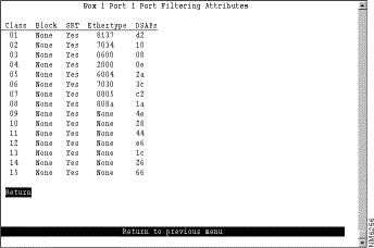
The following information is displayed on this panel:
| To | Select | Then |
|---|---|---|
Change the current settings | The appropriate parameter... | Specify the value. |
Save your changes | Return |
|
To ensure that the address tables (per port and master) are kept to a minimum size, you can configure an aging limit. The aging limit is used to determine when inactive MAC addresses are removed from the address table. To define address table aging limits, select Address Aging from the Configuration Menu. The Address Aging panel (Figure 5-35) is displayed.
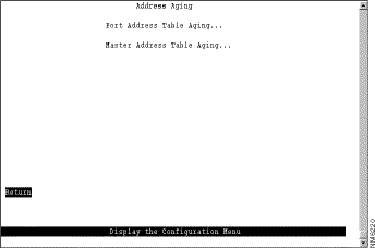
The following options are displayed on this panel:
To define the address aging limits of each port, select Port Address Table Aging on the Address Aging panel. The Port Address Table Aging panel (Figure 5-36) is displayed.
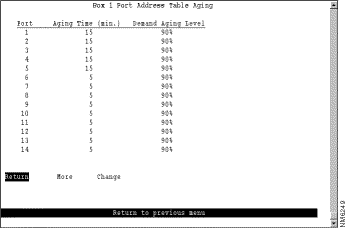
The following information is displayed on this panel:
| To | Select | Then |
|---|---|---|
Change the aging time limit and the address table aging level | Change | Specify the port, the new aging time, and the new aging level. |
Disable address removal for a port based on address age | Change | Specify an Aging Time of 0. |
Disable address removal for a port based on address table capacity | Change | Specify a Demand Aging Level of Disable. |
Save your changes | Return |
|
To define the address aging limits of the master address table, select Master Address Table Aging on the Address Aging panel. The Master Address Table Aging panel (Figure 5-37) is displayed.
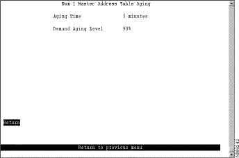
The following information is displayed on this panel:
| To | Select | Then |
|---|---|---|
Change the aging time limit or the address table aging level | The appropriate parameter | Specify the new value. |
Disable address removal based on address age | Aging Time | Specify 0. |
Disable address removal based on address table aging level | Demand Aging Level | Specify Disable. |
Save your changes | Return |
|
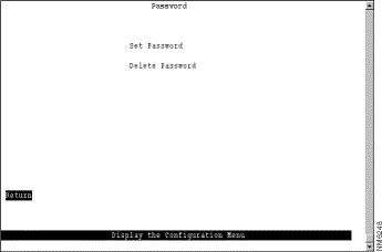
The Catalyst 3920 allows you to set a password to protect its configuration. If you establish a password, users must enter it to obtain access to the Main Menu. To set a password, select Password on the Configuration Menu. The Password panel (Figure 5-38) is displayed.
| To | Select | Then |
|---|---|---|
Add a password | Set Password | Press Enter at the Old Password prompt and specify a new password. |
Change the password | Set Password | Specify the current password and the new password. |
Delete the password | Delete Password | Specify the current password. |
Save your changes | Return |
|
![]()
![]()
![]()
![]()
![]()
![]()
![]()
![]()
Posted: Tue Oct 12 13:45:06 PDT 1999
Copyright 1989-1999©Cisco Systems Inc.