|
|

Catalyst 3900s can be interconnected to form large networks. This chapter describes the methods of connecting Catalyst 3900s: using TokenChannels, as a stack in a back-to-back configuration or using a Catalyst Matrix, or using high-speed uplinks.
The Catalyst 3900 allows you to configure TokenChannels. TokenChannels consist of two to eight parallel channels between two Catalyst 3900s. These parallel channels provide improved performance between Catalyst 3900s.
A single TokenChannel can consist of a combination of HDX and FDX connections. For example, a TokenChannel consisting of three connections can have one HDX and two FDX connections. However, both ports in each interconnected pair must be either HDX or FDX. In addition, all ports in a single TokenChannel must belong to the same TrCRF on the Catalyst 3900.
 | Caution While you can use TokenChannels to interconnect Catalyst 3900s and Catalyst 3920s, you cannot use TokenChannels to interconnect other different models of switches. For example, you cannot use a TokenChannel to interconnect a Catalyst 2600 and a Catalyst 3900. Likewise, you cannot use a TokenChannel to interconnect a Catalyst 3900 and a non-Cisco switch. |
A stack of Catalyst 3900 switches is not just a connection of several switches. A stack of Catalyst 3900 switches combine to form a "virtual" single switch.
A Catalyst stack is configured in one of the following two ways:
Two Catalyst 3900 switches can be connected to form a stack by using only a stack port cable and an interface card (Catalyst stack port module) plugged into the back of each Catalyst 3900. This creates a direct connection between the two Catalyst 3900 switches, which is referred to as a back-to-back stack. As an alternative, you can use an 8-port Catalyst Matrix switch to create a stack of up to eight Catalyst 3900 switches. The ProStack port operates in FDX mode at speeds of 140 Mbps. It switches packets at wire speeds with low forwarding latency. A proprietary 4-byte header is used to allow the members of the stack to function as one operational system.
When you power-on a Catalyst 3900, it runs through a set of self-diagnostics. Immediately after the diagnostics are completed, the Catalyst 3900 runs through a stack discovery mode. This discovery mode is used to sense whether the switch is cabled to another Catalyst 3900. If it is determined during the discovery mode that the Catalyst 3900 is connected to other switches, the switches are automatically combined to form a stack. At the end of the discovery mode, if it is determined that the Catalyst 3900 is not connected to another switch, it will operate as a stand alone switch.
Advantages of the stack include the following:
Catalyst 3900 release 2.1(1) and later includes support for larger frame sizes. The use of larger frame sizes in a stacked configuration requires revision B of the Stack Port module. The initial release of the Catalyst 3900 Stack Port module (which is identified as revision A) did not support MTUs greater than 4472. Revision B of the Catalyst 3900 Stack Port module supports MTUs of up to 18190. When configuring MTUs, keep the following in mind:
If you attempt to create a stack that contains switches that have both revision A and revision B stack ports, the stack will not completely form. If the controlling switch (the first switch in the stack to come up) contains a revision A module, only the switches with revision A modules will be able to join the stack. Likewise, if the controlling switch contains a revision B module, only the switches with revision B modules will be able to join the stack.
To verify the revision level of a stack port module on a Catalyst 3900, see the Module Information panel. The panel has been updated to include the revision level of the stack port module in the HW Rev field. A Stack Port module Revision B will be displayed as 0.B.
A proprietary shielded cable, 1 meter in length, with 50-pin connectors, is used to connect the Catalyst switches together. After power-on diagnostics, the stack discovery mode runs. If, during this stack discovery mode, a Catalyst 3900 senses that it is connected to another Catalyst 3900 in a back-to-back configuration, the two switches will begin to form a stack.
As soon as the stack discovery mode is completed, two things happen:
After a stack has formed and sets up the interbox parameters, the stack operates the same way whether it is in a back-to-back configuration or is in a multi-unit configuration using the Catalyst Matrix interface.
Using a Catalyst Matrix, a multi-unit stack of up to 8 Catalyst 3900 switches can be created. The following sections describe how this multi-unit stack is formed.
The Catalyst Matrix is an eight-port switch matrix interface that connects up to eight Catalyst 3900 switches. The Catalyst 3900 senses if it is connected to a Catalyst Matrix and also senses if there are other Catalyst 3900 switches connected to that Catalyst Matrix. The connected Catalyst 3900 switches and the Catalyst Matrix combine logically to form a stack.
Any combination of up to eight Catalyst 3900 switches can be connected to or disconnected from the Catalyst Matrix while it, or any of the switches, are powered on or powered off. A proprietary shielded cable, 1 meter in length, with 50-pin connectors, is used to connect the Catalyst stack equipment together. The cable has cross-over wiring so either end can connect to the Catalyst Matrix, or to the Catalyst 3900 switches. The cable is plugged directly into a stack port I/O connector on the back of the Catalyst Matrix. The other end is plugged into a Catalyst stack port module interface card that is installed in the rear expansion slot in the Catalyst 3900.
When Catalyst 3900 switches first power up, they run through a set of self-diagnostics. Immediately after the diagnostics are completed, the Catalyst 3900 switches run through a stack discovery mode. During this stack discovery mode, if two or more Catalyst 3900 switches are connected to a Catalyst Matrix, the switches will sense the connection and combine logically to create a stack configuration.
As soon as the stack discovery mode is completed, each Catalyst 3900 is assigned a box number. With a Catalyst Matrix configuration, the box number for a Catalyst 3900 is determined by the port number the Catalyst 3900 is connected to on the Catalyst Matrix. For example, the Catalyst 3900 plugged into port 3 on the Catalyst Matrix becomes box 3. The box number remains constant as long as that switch is plugged in to that port. If a Catalyst 3900 is moved to another port, the box number for that Catalyst 3900 will change to the number of the port it is moved to.
For a stack to operate as a single entity, the interbox parameters must be the same in all of the switches in a stack. The "Interbox Parameters" section later in this chapter lists the shared parameters. There are two possible ways of providing configuration information to the Catalyst 3900 switches in a stack. These methods are as follows:
If Catalyst 3900s have formed a stack and any additional Catalyst 3900s are added to the stack, the new switches will join the existing stack by altering their interbox parameters to match those of the existing stack.
After a stack has formed and sets up the interbox parameters, the stack operates the same way whether it is in a back-to-back configuration or is in a multi-unit configuration using the Catalyst Matrix interface.
When a stack is formed, certain configuration information within all of the different Catalyst 3900 switches must combine to form a common configuration (interbox parameters). The stack operates as a single entity when all of the Catalyst 3900 switches in that stack use the same interbox parameters.
The following is a list of these shared interbox parameters. The parameters in this list are accessed through the console configuration menus. The console menus are described in "Configuring the Catalyst 3900" chapter.
You can also interconnect Catalyst 3900s using high-speed uplinks, such as the ATM module or the ISL module.
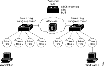
Figure 3-1 shows how the ATM expansion module can be used to connect Catalyst 3900 switches through an ATM switch.

The ATM expansion module is well suited for the following environments:
Because one ATM expansion module can support as many LECs as there are VLANs in a Catalyst 3900, the question arises: Why use two ATM expansion modules?
The first reason is to provide a backup LEC. By enabling two LECs on two different ATM expansion modules to be members of both the same VLAN and the same emulated LAN, the Catalyst 3900's spanning-tree operation will automatically use one LEC for forwarding frames and the other LEC for blocking frames (active standby). For the backup LEC configuration to work, spanning tree must be enabled for the related LAN switch domain.
The second reason to use two ATM expansion modules is to increase system resources. In some environments the resources associated with a single ATM expansion module (such as a maximum of 2048 VCCs per ATM expansion module and a maximum data rate of 155 Mbps) might affect individual LEC performance. By moving one or more LECs to a second ATM expansion module, you can significantly increase the resources available to each LEC.
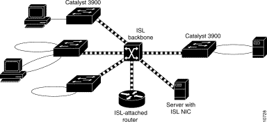
The ISL backbone design looks very much like an ATM design, however, ISL is less expensive than ATM and avoids the need for LANE services. It is primarily intended for network managers who do not want an ATM backbone for the campus. In the future, routing between Token Ring VLANs will be provided via an ISL-attached router or the route switch module in the Catalyst 5500. Figure 3-2 shows an example of the ISL backbone design.

The Catalyst 5000 family of switches should be used to provide the ISL backbone. The Catalyst 3900 switch can then be connected to this backbone via the dual 100-Mbps ISL expansion module. In addition, vendors are developing ISL network interface cards (NICs) that supports both Token Ring and Ethernet VLANs. These NICs can be used for high-speed attachment to servers.
If you want to attach the Catalyst 3900 ISL port to the ISL port of a Catalyst 5000, you must manually configure the ISL port on the Catalyst 5000 for 100 Mbps (using the set port speed command) and full-duplex mode (using the set port duplex command).
While your Catalyst 3900 can contain both an ATM expansion module and an ISL expansion module, you cannot use both in a parallel configuration. If the ATM module and the ISL module are configured for parallel connections, the Spanning-Tree Protocol will allow only one of the trunk ports to be active at a time.
Because ISL is used to propagate VLAN trunking information, it is important for the ISL module to be the active path in an ISL-ATM parallel connection. Therefore, the path cost is calculated based on a 200-Mbps connection, which results in a path cost of 5 and causes the Spanning-Tree Protocol to place the ISL port in forwarding mode and the ATM port in blocked mode.
![]()
![]()
![]()
![]()
![]()
![]()
![]()
![]()
Posted: Tue Dec 17 21:40:50 PST 2002
All contents are Copyright © 1992--2002 Cisco Systems, Inc. All rights reserved.
Important Notices and Privacy Statement.