|
|

Table F-1 lists the type of cables that are used when connecting to the EIA 232 port on the Catalyst 3900.
| Cable Function | Cable Type or Cable Solution |
|---|---|
Connect a modem to the EIA 232 port. | Connect one end of a straight-through, EIA 232 modem cable to the EIA 232 port and the other to the modem. |
Connect a PC or other DTE device to the EIA 232 port. | Connect one end of a crossover EIA 232 cable to the EIA 232 port and the other end to the PC or DTE device. Attach a null-modem adapter to the EIA 232 port, then attach a straight-through modem cable to the null-modem adapter. |
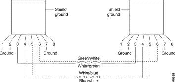
When connecting devices to the Token Ring ports on the Catalyst 3900, you must use a straight-through cable (Figure F-1).
The Catalyst 3900 RJ-45 connector makes ground available on the shield and on pins 1, 2, 7, and 8. Shielded cables will provide continuity for ground to any shielded connector on the other end of the cable.

For a terminal connection, you can use either a null-modem cable or a modem cable with a null-modem adapter attached. For a modem connection, you can use a standard modem cable.
This section provides pinout information for the cables you can use to connect to the EIA 232 port.
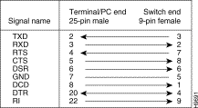
Use a straight-through modem cable to connect the EIA 232 port of the Catalyst 3900 to a modem (Figure F-2).

Use a null-modem (crossover) cable (Figure F-3) to connect the EIA 232 port to a terminal (DTE) with a 25-pin connector. Alternatively, you can use a modem cable and a null-modem adapter. Data Terminal Ready (DTR), pin 20, and Ready to Send (RTS), pin 4, must be on, or high, on your terminal or in your terminal emulation program.

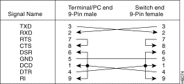
Use a null-modem (crossover) cable (Figure F-4) to connect the EIA 232 port to a terminal (DTE) with a 9-pin connector. Alternatively, you can use a modem cable and a null-modem adapter. DTR (pin 4) and RTS (pin 7) must be on, or high, on your terminal or in your terminal emulation program.

Table F-2 and Table F-3 contain the maximum supported lobe lengths. The maximum lengths reflect the longest lengths supported by the transmission characteristics of IEEE 802.5-compliant adapters. The recommended distances for the various cable types are set by North American and international commercial building wiring standards. It is good practice to follow the cabling standards guidelines when installing building cabling to help ensure a longer useful life for your cabling infrastructure, migration to new technologies, and maximum flexibility for the network configuration.
| Cable Type | Impedance |
|---|---|
Type 1 and 1A | 150 ohm |
Type 2 and 2A | 150 ohm |
Type 8 | 150 ohm |
Type 9 | 150 ohm |
Type 3 | 100 ohm |
Category 3 | 100 and 120 ohm |
Category 4 | 100 and 120 ohm |
Category 5 | 100 and 120 ohm |
| Cable Type |
|---|
65.5/125 Micron Fiber |
50/125 Micron Fiber |
100/140 Micron Fiber |
If you are installing new cabling for data applications, it is recommended that you use the following types of cable:
The IBM Token Ring Network dedicated-media connections support only one attached entity (workstation or Catalyst 3900) per connection. In a Token Ring network, the section of cable that attaches a device to an access unit is called a lobe.
For all supported cable types except optical fiber, the recommended maximum cable lobe length is 625 feet (190 m) plus a 33 foot (10 m) total allowance for the patch cords in the office and the telecommunications closets. For optical fiber, the recommended maximum cable lobe length is 6562 feet (2000 m).
Table F-4, Table F-5, Table F-6, and Table F-7 specify the maximum supported lobe lengths for the following types of cables.
An additional 33 feet (10 m) per lobe length is allowed to accommodate patch cables, unless otherwise specified.
| Ring Speed | Types 1 and 1a, Types 2 and 2a | Type 8 | Type 9 |
|---|---|---|---|
4 Mbps | 2460 feet (750 m) | 1234 feet (376 m) | 1640 feet (500 m) |
16 Mbps | 952 feet (290 m) | 480 feet (146 m) | 656 feet (200 m) |
| Ring Speed | 100-Ohm Type 3 | 100-Ohm Category 3 |
|---|---|---|
4 Mbps | 328 feet (100 m) | 820 feet (250 m) |
16 Mbps | Not supported | 328 feet (100 m) |
| Ring Speed | 100- or 120-Ohm Category 4 | 100- or 120-Ohm Category 5 |
|---|---|---|
4 Mbps | 1148 feet (350 m) | 1148 feet (350 m) |
16 Mbps | 656 feet (200 m) | 656 feet (200 m) |
| Ring Speed | 100-Ohm Type 3 | 100-Ohm Category 3 | 100- or 120-Ohm Category 4 | 100- or 120-Ohm Category 5 |
|---|---|---|---|---|
4 Mbps | 328 feet (100 m) | 820 feet (250 m) | 1148 feet (350 m) | 1148 feet (350 m) |
16 Mbps | Not supported | 328 feet (100 m) | 656 feet (200 m) | 656 feet (200 m) |
The types of cables that can be used are the same as those described for dedicated-media segments. The acceptable distances are defined by the hub or concentrator attached to the Catalyst 3900 port.
A Token Ring network supports up to 260 attaching devices or nodes on a single network when using 150-ohm shielded media (type 1, 1A, 2, or 2A). When cable segments in the network are 100 or 120 ohm, this number is decreased to 132 (72 if using any 4-Mbps-only adapters or filters).
![]()
![]()
![]()
![]()
![]()
![]()
![]()
![]()
Posted: Wed Oct 2 02:57:08 PDT 2002
All contents are Copyright © 1992--2002 Cisco Systems, Inc. All rights reserved.
Important Notices and Privacy Statement.