|
|

This appendix describes the connectors, cables, and adapters that you use to connect the switch to other devices.
These sections describe the connectors used with the Catalyst 2950 switches and contains this information:
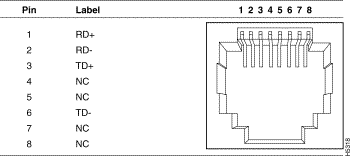
The 10/100 Ethernet ports use standard RJ-45 connectors and Ethernet pinouts with internal crossovers, as shown by an X in the port name. These ports have the transmit (TD) and receive (RD) signals internally crossed so that a twisted-pair straight-through cable and adapter can be attached to the port. Figure B-1 shows the pinout.
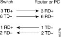
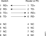
When connecting 10/100 ports to other devices, such as servers, workstations, and routers, you can use a two or four twisted-pair, straight-through cable wired for 10BASE-T and 100BASE-TX. Figure B-6 shows the two twisted-pair, straight-through cable schematics. Figure B-8 shows the four twisted-pair, straight-through cable schematics.
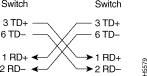
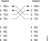
When connecting the ports to other devices, such as switches or repeaters, you can use a two or four twisted-pair, crossover cable. Figure B-7 shows the two twisted-pair, crossover cable schematics. Figure B-9 shows the four twisted-pair, crossover cable schematics.
You can use Category 3, 4, or 5 cabling when connecting to 10BASE-T devices. You must use Category 5 cabling when connecting to 100BASE-TX devices.
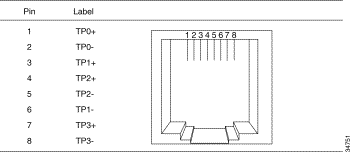
The 10/100/1000 Ethernet ports on Catalyst 2950T-24 switches use standard RJ-45 connectors. Figure B-2 shows the pinout.
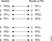
When connecting the ports to 10BASE-T and 100BASE-TX devices, such as servers, workstations, and routers, you can use a two or four twisted-pair, straight-through cable wired for 10BASE-T and100BASE-TX. Figure B-6 shows the two twisted-pair, straight-through cable schematics. Figure B-8 shows the four twisted-pair, straight-through cable schematics.
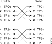
When connecting the ports to 10BASE-T- and 100BASE-TX devices, such as switches or repeaters, you can use a two or four twisted-pair, crossover cable. Figure B-7 shows the two twisted-pair, crossover cable schematics. Figure B-9 shows the four twisted-pair, crossover cable schematics.
You can use Category 3, 4, or 5 cabling when connecting to 10BASE-T devices. You must use Category 5 cabling when connecting to 100BASE-TX devices.
When connecting the ports to 1000BASE-T devices, such as servers, workstations, and routers, you must use a four twisted-pair, Category 5, straight-through cable wired for 10BASE-T, 100BASE-TX, and 1000BASE-T. Figure B-10 shows the straight-through cable schematics.
When connecting the ports to other devices, such as switches or repeaters, you must use a four twisted-pair, Category 5, crossover cable. Figure B-11 shows the crossover cable schematics.
 |
Note Be sure to use a four twisted-pair, Category 5 cable when connecting to a 1000BASE-T device. |
The 100BASE-FX multimode (MM) fiber-optic ports use MT-RJ connectors, shown in Figure B-3. These ports use 50/125- or 62.5/125-micron multimode fiber-optic cabling.
For MM connections, use one of the LCs listed in Table B-1. Use the Cisco part numbers in Table B-1 to order the patch cables that you need.
 |
Warning LED radiation is present when the system is open. |
|
Warning Class 1 LED product |
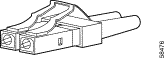
The 100BASE-LX single-mode (SM) fiber-optic ports use LC-type connectors, shown in Figure B-4. These ports use 9/125-micron single-mode fiber-optic cabling.
|
Warning Invisible laser radiation may be emitted from disconnected fibers or connectors. Do not stare into beams or view directly with optical instruments. |
|
Warning Class 1 laser product |
For SM connections, use one of the LCs listed in Table B-2. Use the Cisco part numbers in Table B-2 to order the connectors that you need.
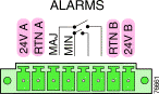
The power and relay connector is a pluggable screw terminal block connector that provides power and return connections for both the primary and secondary power supplies. The power and relay connector also gives the Catalyst 2955 switch the interfaces to two independent alarm relays.
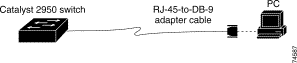
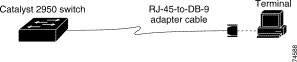
The console port uses an 8-pin RJ-45 connector. You can connect a switch to a PC through the console port and the supplied RJ-45-to-DB-9 adapter cable. If you want to connect a switch to a terminal, you need to provide an RJ-45-to-DB-25 female DTE adapter. You can order a kit (part number ACS-DSBUASYN=) with that adapter from Cisco. For console-port and adapter-pinout information, see Table B-3 and Table B-4.
These sections describe the cables and adapters used with Catalyst 2950 switches.
Figure B-6 and Figure B-7 show the schematics of two twisted-pair cables for 10/100 ports.
Figure B-8 and Figure B-9 show the schematics of four twisted-pair cables for 10/100 ports.
Figure B-10 and Figure B-11 show the schematics of four twisted-pair cables for 10/100/1000 ports on Catalyst 2950T-24 switches and 1000BASE-T ports.
This section describes the cable and adapter pinouts and also describes how to identify a rollover cable.
Use the supplied RJ-45-to-DB-9 adapter cable to connect the console port to a PC running terminal-emulation software. Figure B-12 shows how to connect the console port to a PC. Table B-3 lists the pinouts for the console port and the RJ-45-to-DB-9 adapter cable.
Table B-3 Console Port Signaling and RJ-45-to-DB-9 Adapter Cabling
| Console Port (DTE) | RJ-45-to-DB-9 Adapter Cable | Console Device | |
|---|---|---|---|
| Signal | RJ-45 Pin | DB-9 Pin | Signal |
Use the supplied RJ-45-to-DB-9 adapter cable and an RJ-45-to-DB-25 female DTE adapter to connect the console port to a terminal. Figure B-13 shows how to connect the console port to a terminal. Table B-4 lists the pinouts for the console port, the adapter cable, and the RJ-45-to-DB-25 adapter.
|
Note The RJ-45-to-DB-25 female DTE adapter is not supplied with the switch. You can order a kit (part number ACS-DSBUASYN=) with that adapter from Cisco. |
Table B-4 Console Port Signaling and Cabling Using a DB-25 Adapter
| Console Port (DTE) | RJ-45-to-DB-9 Adapter Cable | RJ-45-to-DB-25 Terminal Adapter | Console Device | |
|---|---|---|---|---|
| Signal | RJ-45 Pin | DB-9 Pin | DB-25 Pin | Signal |
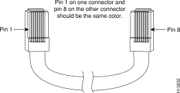
You can identify a rollover cable by comparing the two modular cable ends. Hold the cable ends side-by-side, with the tab at the back. The wire connected to the pin on the outside of the left plug should be the same color as the wire connected to the pin on the outside of the right plug. (See Figure B-14.)
![]()
![]()
![]()
![]()
![]()
![]()
![]()
![]()
Posted: Thu Jun 5 11:59:28 PDT 2003
All contents are Copyright © 1992--2003 Cisco Systems, Inc. All rights reserved.
Important Notices and Privacy Statement.