April 1997
To enhance the advantages of the Catalyst 2600 Token Ring switch, the switch now provides a source-route bridging (SRB) function. You can divide the ports of the Catalyst 2600 into as many as eight virtual domains by assigning a different segment number to each port. SRB allows the Catalyst 2600 to switch frames between the ports with different segment numbers. This allows any combination of Catalyst 2600 domains to be interconnected internally by a multiport source-route bridge. In addition, SRB dynamically updates the maximum frame size for each route, eliminating the need to configure the frame size at each workstation in the network.
This Catalyst 2600 release note discusses the following topics:
 | Caution A Catalyst 2600 with an ATM feature card can use only source-route switching. The internal source-route bridge function available with software release 3.11 cannot be used in a Catalyst 2600 that has an ATM feature card installed. |
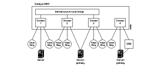
Figure 1 shows a single Catalyst 2600 configured with multiple domains and with SRB enabled to eliminate multiple, external source-route bridges. In this example, the Catalyst 2600 is configured with four virtual domains, which use source-route switching within the domain. Three of the domains are enabled for SRB between domains. Both explorer and specifically routed frames are source-route bridged to other domains. The internal SRB eliminates the need for up to three external source-route bridges.
Figure 1: Using the Internal Source-Route Bridging Function
To support SRB, the Catalyst 2600 uses an additional Management Information Base (MIB): the Source-Route Bridge MIB described in RFC 1525. This MIB is contained on the disk.
The Catalyst 2600 supports two forms of source routing: source-route switching and SRB. Source-route switching forwards source-routed frames only to ports assigned to the same virtual domain (those with the same segment number). SRB switches frames between segments assigned to different domains (those with different segment numbers).
You can use virtual domains to limit traffic to only those ports assigned to the same domain. However, if you want traffic to be forwarded between domains, you can enable SRB between the domains. With SRB enabled:
- Source-routed frames that originate in one domain and are destined for an address in another domain are switched between the domains.
- Source-routed frames that originate in one domain and are destined for an address in the same domain are not switched across the source-route bridge.
In Figure 1, source-routed frames can travel from any domain attached to the internal source-route bridge to any other domain attached to the internal source-route bridge. In this example, a source-routed frame can pass from Domain 1 across the internal source-route bridge to Domain 2. However, Domain 4 is not attached to the internal source-route bridge and source-routed frames that originate in Domain 4 cannot pass into Domains 1, 2, or 3.
The Catalyst 2600 is made aware of segment numbers either by learning them from the network or by explicit user configuration. To learn the local segment number, the Catalyst 2600 must have received a source-routed explorer frame on any port in the domain from a resource on the other side of a source-route bridge.
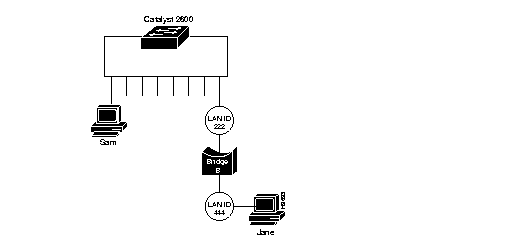
Figure 2 illustrates an example of a small network with an external source-route bridge (Bridge B). The local segment number is 222, which the Catalyst 2600 learns when it receives a frame that has been sent from Station Jane through Bridge B. Once the Catalyst 2600 has learned a local segment number, it will not relearn the segment number. Therefore, if a change in the network configuration causes the local segment number to change, you must use the Source-Route Configuration panels to either clear the learned segment number (to allow the new one to be learned) or assign a segment number.
Figure 2: External Source-Route Bridged Network
In support of SRB, an Internal Source-Route Bridge Configuration option has been added that allows you to:
- Assign or change LAN segment bridging parameters
- Configure the internal source-route bridge
To clear the current LAN segment number or manually configure a LAN segment number, select Source Route Configuration on the Configuration panel. The Source Route Configuration panel (Figure 3) is displayed.
Figure 3: Source Route Configuration Panel
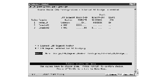
The following information is displayed on this panel:
- Index--The identifier of the source-route entry.
- Domain--The domain name.
- LAN Segment Number--The LAN segment number, or ring number, in hexadecimal. The default is "unknown." An asterisk (*) beside the number indicates that the ID was learned by the Catalyst 2600. A pound sign beside the number indicates that the LAN segment has been enabled for SRB.
- Base and Slots--The ports of the switch (Base) or a Feature Card (Slot) that belong to this domain. Ports that belong to a specified domain are indicated by an X in the appropriate Ports column.
|
To
| Select
| Then
|
|---|
| Manually assign a LAN segment number...
| Assign_LAN_Segment_Number
| Specify the index number of the entry (if more than one entry exists) and specify the LAN segment number.
|
| Clear the current LAN segment number (to enable re-learning)...
| Assign_LAN_Segment_Number
| Specify the index number of the entry (if more than one entry exists) and specify a null LAN segment number.
|
| Configure the internal source-route bridge...
| Configure Internal SR Bridge
| Refer to the "Configuring the Internal Source-Route Bridge" section.
|
| Save your changes...
| Return
|
|
A domain must have a segment number before it can be enabled for SRB. If the domain is enabled for SRB, the LAN segment number cannot be changed.
To set global parameters for the internal source-route bridge function, select Configure_Internal_SR_Bridge on the Source-Route (SR) Configuration panel. The Internal Source-Route Bridge (SRB) Configuration panel (Figure 4) is displayed.
Figure 4: Internal Source-Route Bridge Configuration Panel
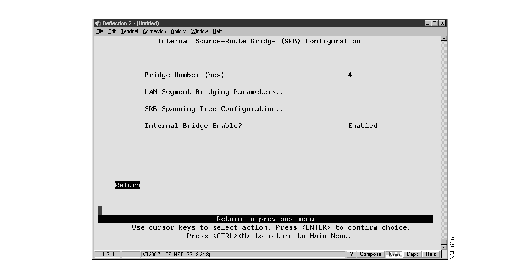
The following information is displayed on this panel:
- Bridge Number--The internal bridge number used in source-route descriptors. The range is 0 through F. The default is 1. Changes in the bridge number are effective immediately. Therefore, a confirmation message is displayed when you change the bridge number and the internal source-route bridge is enabled.
- Internal Bridge Enabled--Indicates whether you want to enable or disable the internal source-route bridge. The changes are effective immediately. Therefore, a confirmation message is displayed when you change the state of the internal source-route bridge. If there are fewer than two segments enabled for bridging, an error message is displayed and SRB is enabled.
To display the source-route bridge parameters for individual segments, select LAN Segment Bridging Parameters on the Internal Source-Route Bridge (SRB) Configuration panel. The LAN Segment Bridging Parameters panel (Figure 5) is displayed.
Figure 5: LAN Segment Bridging Parameters Panel
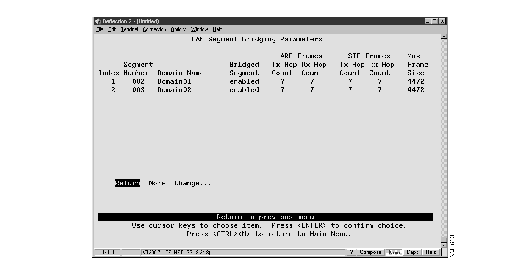
The following information is displayed on this panel:
- Index--The identifier of the LAN segment bridging entry.
- Segment Number--The LAN segment number, or ring number, in hexadecimal.
- Domain name--The assigned domain name.
- Bridged Segment--Indicates whether the segment is enabled for SRB.
- ARE Frames Tx Hop Count--The maximum number of hops through which an all-routes explorer (ARE) frame can be transmitted. ARE frames to be transmitted that have a hop count that exceeds the specified value are discarded.
- ARE Frames Rx Hop Count--The maximum number of hops from which an ARE frame can be received. ARE frames received that have a hop count that exceeds the specified value are discarded.
- STE Frames Tx Hop Count--The maximum number of hops through which a spanning-tree explorer (STE) frame can be transmitted. STE frames to be transmitted that have hop count that exceeds the specified value are discarded.
- STE Frames Rx Hop Count--The maximum number of hops from which an STE frame can be received. STE frames received that have hop count that exceeds the specified value are discarded
- Max Frame Size--The maximum frame size (in bytes) for frames that are forwarded on this segment.
|
To
| Select
| Then
|
|---|
| Change the internal bridging parameters for a LAN segment
| Change
| Specify the index number of the segment, and then refer to the "Changing LAN Segment Bridging Parameters" section.
|
| Save your changes...
| Return
|
|
To change the LAN segment bridging parameters for a specific segment, select Change on the LAN Segment Bridging Parameters panel and specify the index number of the desired segment. The Change LAN Segment Bridging Parameters panel (Figure 6) is displayed.
Figure 6: Change LAN Segment Bridging Parameters Panel
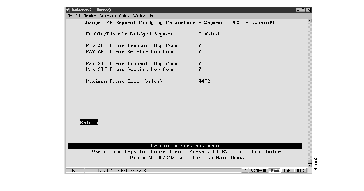
The following information is displayed on this panel:
- Enable/Disable Bridged Segment--Indicates whether the segment is enabled for SRB.
- Max ARE Frames Tx Hop Count--The maximum number of hops through which an ARE frame can be transmitted. The valid range is 1 through 13. The default is 7.
- Max ARE Frames Rx Hop Count--The maximum number of hops from which an ARE frame can be received. The valid range is 1 through 13. The default is 7.
- Max STE Frames Tx Hop Count--The maximum number of hops through which an STE frame can be transmitted. The valid range is 1 through 13. The default is 7.
- Max STE Frames Rx Hop Count--The maximum number of hops from which an STE frame can be received. The valid range is 1 through 13. The default is 7.
- Maximum Frame Size--The maximum frame size for frames that are forwarded on this segment. Valid values are 516, 1500, 2052, and 4472. The default is 4472.
Note The values for maximum frame size that are allowed in the SRB MIB (RFC 1525) are the IEEE values of 516, 1470, 2052, and 4399. Two of these values differ from the IBM values specified above. The Catalyst 2600 always uses the larger IBM values. However, when an SNMP-based manager is used to retrieve this setting, the smaller IEEE value is returned.
| To
| Select
| Then
|
|---|
| Change the current settings...
| The appropriate parameter...
| Enter the new value.
|
| Save your changes...
| Return
|
|
To change the spanning-tree parameters for SRB, select SRB Spanning Tree Configuration on the Internal Source-Route Bridge (SRB) Configuration panel. The Source-Route Bridge Spanning Tree Configuration panel (Figure 7) is displayed.
Figure 7: Source-Route Bridge Spanning Tree Configuration Panel
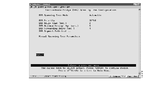
The following information is displayed on this panel:
- SRB Spanning Tree Mode--Indicates whether the internal source-route bridge uses automatic or manual spanning-tree mode. The default is manual.
- In automatic mode, the internal source-route bridge is allowed to participate in the source-route spanning-tree algorithm with other source-route bridges to determine a single route through the source-routing network for STE frames.
- In manual mode, you can specify which logical bridge ports forward STE frames.
- SRB Priority--The priority assigned to the bridge. The bridge with the highest priority in the spanning tree becomes the root bridge. Valid values are 0 through 65535. The default is 32768. The lower the value, the higher the priority. This option can be used only if the SRB Spanning Tree mode is set to automatic.
- SRB Hello Time--The time (in seconds) the bridge waits before sending the next source-route spanning-tree configuration message when the bridge is the root. The minimum valid value is 1. The maximum valid value is the lower of 10 or (SRB Maximum Message Age/2) - 1. The default is 2. This option can be used only if the SRB Spanning Tree mode is set to automatic.
- SRB Maximum Message Age--The time (in seconds) that can pass until the configuration message used by the spanning-tree algorithm should be discarded when this bridge is the root bridge. The minimum value is the higher of 6 or 2 x (SRB Hello Time + 1). The maximum valid value is the lower of 40 or 2 x (SRB Forwarding Delay - 1). The default is 20. This option can be used only if the SRB Spanning Tree mode is set to automatic.
- SRB Forwarding Delay--The time (in seconds) that the bridge spends in listening state when it is the root bridge. The minimum is the larger of 4 or (SRB Maximum Message Age/2) + 1. The maximum is 30. The default is 15. This option can be used only if the SRB Spanning Tree mode is set to automatic.
To change the path cost for a source-route bridge segment, select SRB Segment Path Cost on the Source-Route Bridge (SRB) Spanning Tree Configuration panel. The Source-Route Bridge (SRB) Path Cost panel (Figure 8) is displayed.
Figure 8: Source-Route Bridge (SRB) Path Cost Panel
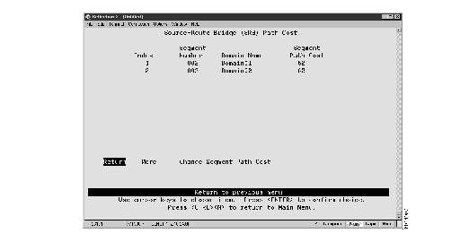
The following information is displayed on this panel:
- Index--The identifier of the source-route entry.
- Segment Number--The LAN segment number, or ring number, in hexadecimal.
- Domain Name--The assigned domain name.
- Segment Path Cost--The cost associated with the segment. The Spanning-Tree Protocol uses port path costs to determine which logical bridge ports are in forwarding state for STE frames. The possible range is 1 through 65535. The default is 62.
|
To
| Select
| Then
|
|---|
| Change the path cost associated with a segment...
| Change Segment Path Cost
| Specify the index number of the LAN segment entry and specify the path cost.
|
| Save your changes...
| Return
|
|
To manually change the forwarding state for a source-route bridge segment, select Manual Spanning Tree Parameters on the Source-Route Bridge (SRB) Spanning Tree Configuration panel. The Source-Route Bridge Manual Spanning Tree Parameters panel (Figure 9) is displayed.
Figure 9: Source-Route Bridge (SRB) Manual Spanning Tree Parameters Panel
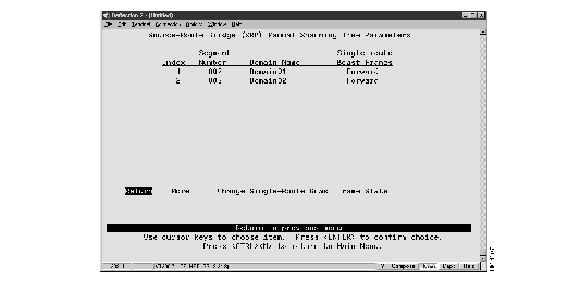
The following information is displayed on this panel:
- Index--The identifier of the source-route entry.
- Segment Number--The LAN segment number, or ring number, in hexadecimal.
- Domain Name--The assigned domain name.
- Single-route Bcast Frames--Indicates whether or not the bridge forwards STE frames to the segment. The default is Forward.
|
To
| Select
| Then
|
|---|
| Change the forwarding state of STE frames for a segment...
| Change Single-Route Bcast Frame State
| Specify the index number of the LAN segment entry and specify Forward or Block.
|
| Save your changes...
| Return
|
|
In support of SRB, the following options have been added to the Status/Statistics Menu:
- SRB Spanning Tree Status
- LAN Segment N SRB Statistics
To display the current status of the source-route Spanning Tree, select Source-Route Bridge Spanning Tree Status on the Status/Statistics Menu. The Source-Route Bridge (SRB) Spanning Tree Status panel (Figure 10) is displayed.
Figure 10: Source-Route Bridge (SRB) Spanning Tree Status Panel
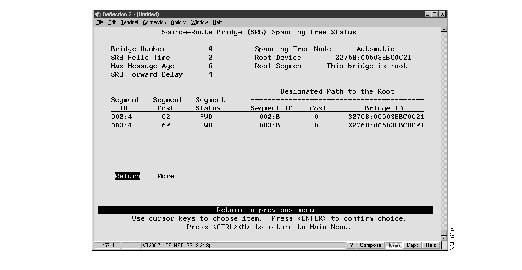
The following information is displayed on this panel:
Note All fields described here appear on the panel when the Spanning Tree Mode is set to Automatic. When the Spanning Tree mode is set to manual, only the Bridge Number, Mode, Segment ID, and Segment Status fields are displayed.
- Bridge Number--The internal bridge number to be used in source-route descriptors.
- SRB Hello Time--The time (in seconds) the bridge waits before sending the next source-route spanning-tree configuration message when the bridge is the root.
- SRB Max Message Age--The time (in seconds) that can pass until the configuration message used by the spanning-tree algorithm should be discarded when this bridge is the root bridge.
- SRB Forward Delay--The time (in seconds) that the bridge spends in listening state when it is the root bridge.
- Mode--Indicates whether the internal source-route bridge uses automatic or manual spanning-tree mode.
- In automatic mode, the internal source-route bridge is allowed to participate in the source-route spanning-tree algorithm with other source-route bridges to determine a single route through the source-routing network for STE frames.
- In manual mode, you can specify which logical bridge ports forward STE frames.
- Root Device--The priority and MAC address of the device in the source-route spanning tree that this bridge has accepted as the root.
- Root Segment--The segment number assigned to the segment that is closest to the root. The bridge communicates with the root through this segment.
- Segment ID--The Segment ID (in the form of segment number:bridge number) of the domain.
- Segment Cost--The path cost of the segment. The path cost helps determine the role of the segment in the source-route Spanning Tree.
- Segment Status--The current status of the segment. Possible values are BLK (blocked), LSN (listening), and FWD (forwarding).
- Path to Root Segment ID--The segment ID (in the form of segment number:bridge number) of the segment through which this segment will communicate with the root.
- Path to Root Cost--The cost associated with the path that this segment uses to communicate with the root.
- Path to Root Bridge ID--The priority and MAC address of the device through which this segment must communicate with the root.
To display source-route bridge statistics for a specific LAN segment, select LAN Segment N SRB Statistics on the Status/Statistics Menu. The Choose a LAN Segment panel (Figure 11) is displayed.
Figure 11: Choose a LAN Segment Panel
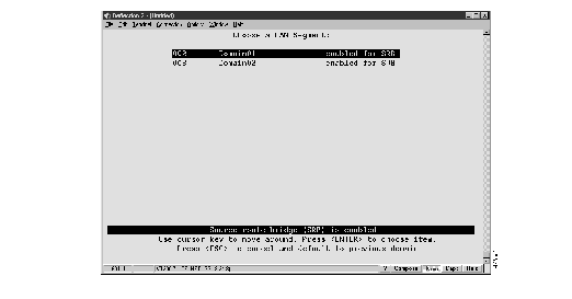
Move your cursor to the desired segment and press Enter. The Source-Route Bridge (SRB) Statistics panel (Figure 12) is displayed.
Figure 12: Source-Route Bridge (SRB) Statistics Panel
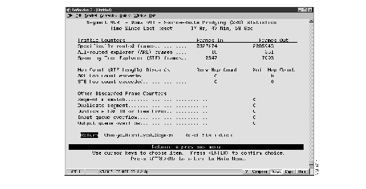
The following information is displayed on this panel:
- Specifically routed frames (Frames In)--The number of specifically routed frames that have entered this domain from the network and then traversed the internal source-route bridge.
- Specifically routed frames (Frames Out)--The number of specifically routed frames that have traversed the internal source-route bridge and then been put out on the network from this domain.
- All-routes explorer (ARE) frames (Frames In)--The number of ARE frames that have entered this domain from the network and then traversed the internal source-route bridge.
- All-routes explorer (ARE) frames (Frames Out)--The number of ARE frames that have traversed the internal source-route bridge and then been put out on the network from this domain.
- Spanning Tree explorer (STE) frames (Frames In)--The number of STE frames that have entered this domain from the network and then traversed the internal source-route bridge.
- Spanning Tree explorer (STE) frames (Frames Out)--The number of STE frames that have traversed the internal source-route bridge and then been put out on the network from this domain.
- ARE hop count exceeded (Recv Hop Count)--The number of ARE frames that have been discarded because the receive hop count was exceeded.
- ARE hop count exceeded (Xmit Hop Count)--The number of ARE frames that have been discarded because the transmit hop count was exceeded.
- STE hop count exceeded (Recv Hop Count)--The number of STE frames that have been discarded because the receive hop count was exceeded.
- STE hop count exceeded (Xmit Hop Count)--The number of STE frames that have been discarded because the transmit hop count was exceeded.
- Segment mismatch--The number of explorer frames that have been discarded because the route descriptor field contained an invalid segment identifier.
- Duplicate segment--The number of explorer frames that have been discarded because the route descriptor field contained a duplicate segment identifier.
- Duplicate LAN ID or Tree Error--The number of STE frames that have been discarded because they appeared at the bridge more than once.
- Input queue overflow--The number of frames that have been discarded because there were insufficient input buffers available to forward them across the internal source-route bridge.
- Output queue overflow--The number of frames that have been discarded because there were insufficient output buffers available to forward them across the internal source-route bridge.
|
To
| Select
| Then
|
|---|
| View statistics for another LAN segment...
| Change Displayed Segment
| Select another LAN segment from the Choose a LAN Segment panel.
|
| Reset the statistics to 0...
| Reset Statistics
|
|
Cisco Connection Online (CCO) is Cisco Systems' primary, real-time support channel. Maintenance customers and partners can self-register on CCO to obtain additional information and services.
Available 24 hours a day, 7 days a week, CCO provides a wealth of standard and value-added services to Cisco's customers and business partners. CCO services include product information, product documentation, software updates, release notes, technical tips, the Bug Navigator, configuration notes, brochures, descriptions of service offerings, and download access to public and authorized files.
CCO serves a wide variety of users through two interfaces that are updated and enhanced simultaneously: a character-based version and a multimedia version that resides on the World Wide Web (WWW). The character-based CCO supports Zmodem, Kermit, Xmodem, FTP, and Internet e-mail, and it is excellent for quick access to information over lower bandwidths. The WWW version of CCO provides richly formatted documents with photographs, figures, graphics, and video, as well as hyperlinks to related information.
You can access CCO in the following ways:
- WWW: http://www.cisco.com
- WWW: http://www-europe.cisco.com
- WWW: http://www-china.cisco.com
- Telnet: cco.cisco.com
- Modem: From North America, 408 526-8070; from Europe, 33 1 64 46 40 82. Use the following terminal settings: VT100 emulation; databits: 8; parity: none; stop bits: 1; and connection rates up to 28.8 kbps.
For a copy of CCO's Frequently Asked Questions (FAQ), contact cco-help@cisco.com. For additional information, contact cco-team@cisco.com.
Note If you are a network administrator and need personal technical assistance with a Cisco product that is under warranty or covered by a maintenance contract, contact Cisco's Technical Assistance Center (TAC) at 800 553-2447, 408 526-7209, or tac@cisco.com. To obtain general information about Cisco Systems, Cisco products, or upgrades, contact 800 553-6387, 408 526-7208, or cs-rep@cisco.com.


