|
|

Demand for network bandwidth continues to grow, driven by the increasing number of systems used in network-intensive applications. LAN segmentation has been the prevalent method for addressing these demands and has been further popularized by trends toward server centralization. However, the implementation costs of LAN segmentation, as well as the real performance characteristics of conventional network components, have served to limit the growth of some Token Ring networks. Alternative technologies for addressing bandwidth demands present other inhibitors, usually relating to costs. Token Ring switching provides users with an easy, cost-effective technique for addressing these demands.
The Catalyst 2600 is a Token Ring switch that provides high-speed forwarding of frames among the shared or dedicated segments attached to each of its ports.
This chapter provides information on the following:
For more information about Token Ring switching, refer to the appendix "Understanding Token Ring Switching."
The Catalyst 2600 can be easily integrated into your existing network, as it is transparent to high-level protocols and provides:
Integration of a Catalyst 2600 in your Token Ring network can relieve network stress and improve performance. The architecture of the Catalyst 2600 centers around the AXIS bus, a 512 Mbps switching fabric through which all switched ports communicate. To avoid the congestion problems that can occur when multiple ports communicate with a single port, each port has 512 KB of buffering, fairness algorithms, and split-buffer schemes.
To address the needs of delay-sensitive data, such as multimedia, this switching fabric contains two data queues. Frames assigned a priority of 5, 6, or 7, such as audio transmissions, are sent to the high-priority queue and given forwarding preference. Frames assigned a priority of 4 or lower are processed through the normal-priority queue.
To provide increased bandwidth, you can use the Catalyst 2600 to create multiple, concurrent paths among connected segments, each path supporting the full,16-Mbps Token Ring bandwidth. With a parallel internal design optimized for performance, the Catalyst 2600 can forward Token Ring frames between each of the pairs of ports simultaneously and at media speeds.
In addition, you can select from three modes of operation for each port on the Catalyst 2600. In cut-through mode, the Catalyst 2600 begins forwarding frames as they are received; it does not wait to receive the entire packet before forwarding. This provides the benefits of dedicated-media, high-speed switching. Store-and-forward mode offers more error isolation between the segments, as the Catalyst 2600 waits until the entire frame is received and checked for errors before forwarding. Adaptive cut-through mode optimizes performance by alternating between cut-through and store-and-forward modes based on user-specified thresholds.
The Catalyst 2600 can forward Token Ring frames among multiple shared or dedicated Token Ring LAN segments. Each of the Token Ring ports on the switch can be connected to a port on any external Token Ring hub or concentrator using a customer-supplied cable. Alternatively, a Token Ring port on the Catalyst 2600 can be connected directly to an HDX- or FDX-Token Ring LAN station without an intervening Token Ring concentrator or hub.
Similar to a transparent bridge, the Catalyst 2600 can forward frames based on MAC address lookup. If you have source-route bridges in your network, the Catalyst 2600 can learn the location of your source-route bridges and forward frames based on the routing information field. This dual frame forwarding technique is called source-route switching. For more information about source-route switching, refer to the section "Source-Route Switching" in the appendix "Understanding Token Ring Switching."
While the Catalyst 2600 provides 16 ports, configurations larger than 16 Token Ring LAN segments can be constructed by:
To help ensure network availability, you can configure redundant (backup) paths in the switch topology. To avoid loops, the Catalyst 2600 allows you to configure spanning-tree parameters. In a spanning tree, a redundant loop is only enabled if the primary path fails.
The Catalyst 2600 provides a series of configuration and management panels which you can access via a console or Telnet connection. Configuration parameters are stored in nonvolatile random-access memory (NVRAM).
Although the Catalyst 2600 provides a fully-functional default configuration, you may want to alter or add to this configuration to suit your specific needs. For example:
To aid in network management, the Catalyst 2600 also maintains status information and a variety of statistics. Status information is available for each port and for each TokenChannel, if defined. Statistics are kept by port, by domain, and for the switch as a whole.
The Catalyst 2600 also contains an SNMP Management Information Base (MIB) II compliant management agent that will allow a customer-supplied SNMP-based network management system (such as CiscoView) to remotely monitor and control the Catalyst 2600.
In addition, the Catalyst 2600 provides Switched Port Analyzer support, which allows you to monitor traffic on any of the Token Ring ports using a customer-supplied monitoring device such as the Network General Sniffer.
Should you need to upgrade the Catalyst 2600 software, upgrades to the functional code can be effected through the same serial port used for configuration. The code can be downloaded from a customer-supplied programmable workstation using the Xmodem protocol. Code upgrades can also be accomplished using TFTP.
Figure 1-1 shows the front of the Catalyst 2600.
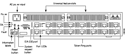
This 9-pin, male, management port functions as a DTE port.
This port enables attachment of a terminal or terminal emulator that is used to customize the switch's configuration, monitor switch activity and status, and test the switch. Console access can be either local, by direct attachment to the EIA 232 port, or remote, through a modem connection.
The EIA 232 port automatically detects the baud rate of the terminal to which it is attached.
The base unit of the Catalyst 2600 has 16, shielded RJ-45 connectors for Token Ring connection. As previously explained, these ports allow half-duplex (HDX) or full-duplex (FDX) connections to other switches, hubs, or end nodes. They support the IBM Cabling System via 150-ohm, shielded twisted-pair (150-ohm STP) or 100- or 120-ohm twisted-pair via Category 3, 4, or 5 cables.
The Catalyst 2600 contains two Universal Feature Slots (see Figure 1-1) that accommodate optional, field-installable, Universal Feature Cards (UFCs) that provide additional connections. Installation and configuration instructions are included with each feature card.
The Catalyst 2600 has a Reset button that is located on the front panel of the switch. Pressing the Reset button resets the hardware and software and clears all tables and memory, including the address tables. Pressing the Reset button does not clear those values stored in non-volatile random access memory (NVRAM).
This unlabeled button, on the front panel next to the Reset button, causes the System Request Menu to appear on the console attached to the serial port. The System Request Menu contains options for downloading new software, resetting the switch, and clearing NVRAM.
 | Caution This function should be used only at the direction of service personnel. The button is recessed to prevent accidental activation. |
The Catalyst 2600 has LEDs that indicate the status and activity of the base switch and the ports. There are three LEDs associated with the base switch: power, operation, and fault. There are three LEDs associated with each of the 16 ports: connection, duplex, transmit/receive.
There are many applications of the Catalyst 2600. This section describes two scenarios that benefit from the addition of a Catalyst 2600: one for a single LAN segment, and one for multiple segments.
The Catalyst 2600 allows you to make incremental changes in your network to address both immediate and long-range performance challenges. For example, Sam works for a growing company and maintains a Token Ring LAN of 80 stations including 4 servers. All of the stations are attached to access units located in a single wiring closet. The LAN is beginning to experience performance problems as a result of increased traffic. The configuration of the LAN is similar to the one pictured in Figure 1-2.
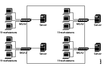
Then, Sam installs a Catalyst 2600. First, Sam divides the LAN into 4 segments (removing the ring-in and ring-out cables that link the access units). One port from each access unit is connected to a port on the Catalyst 2600 via a patch cable. Then, the four servers are removed from the access units to which they have been attached and their cables moved to four ports on the Catalyst 2600. Sam's LAN now looks like the one pictured in Figure 1-3.
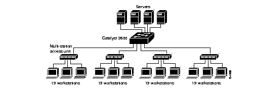
Each group of 19 users attached to an access unit now shares a dedicated, 16-Mbps path to any server. Each server has a dedicated, 16-Mbps path upon which to service requests. The addition of the Catalyst 2600 has increased the network capacity fourfold.
Some large, multisegment, hierarchical, Token Ring networks experience congestion at the campus backbone level. Although this congestion can often be relieved by converting the backbone to a higher speed, shared-media protocol or by installing additional bridges or dual backbones to eliminate bottlenecks, the dedicated media offered by the Catalyst 2600 might be longer-lived or more economical if you foresee using higher demand applications or moving to an ATM WAN. Let's look at an example.
Chris works for a growing company. She maintains a multisegment network that is experiencing congestion at the backbone level and the users are experiencing server access problems. The network is a three-level, hierarchical, campus network like the one pictured in Figure 1-4.
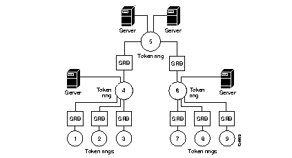
To relieve the backbone congestion, Chris replaces the campus backbone and the attached source-route bridges with a Catalyst 2600.
Next, Chris addresses the performance problems with the servers that were attached to the backbone. The usual mode of operation for a Token Ring adapter is half-duplex. Therefore, the servers can either send or receive information with one other segment attached to the switch. Chris equips the servers with full-duplex adapters and attaches them as single-station segments (as shown in Figure 1-3). This enables the servers to send and receive data simultaneously over a dedicated path. The capacity of each server is now 32 Mbps per port.
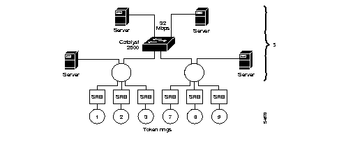
Because all of the ports on the Catalyst 2600 have the same ring number, LAN segments 4, 5, and 6 (shown in Figure 1-4) now have the same segment number (shown as segment 5 in Figure 1-5). This solution:
|
|