|
|

This appendix illustrates a few options for configuring your network. The network configurations describe the following topologies:
Figure E-1 illustrates a typical network configuration using the Cisco Catalyst 1800 Token Ring switch. In this example, five user rings connect to the Catalyst 1800 switch along with three directly attached servers. The workstations and servers have the capability to run transparent or source routed traffic. In this configuration, the backbone ring does not exist because it has been collapsed into the Catalyst 1800 switch. This is the most common configuration for Token Ring switching.
In this configuration, each ring may use the same ring number, have a unique ring number, or any combination of the two.

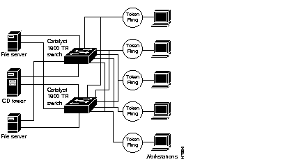
Figure E-2 is an example of a network configuration using the Catalyst 1800 switch in a redundant configuration. In this example, five user rings connect to two Catalyst 1800 switches along with three directly attached servers. Each user ring and server connects to both Catalyst 1800 switches. The redundant configuration provides a fault tolerant network design in case of a failure with a switch, lobe, or cable. Should a switch, lobe port or cable fail, network traffic is rerouted over the alternate path. The workstations and servers can run transparent or source routed traffic. In this configuration the backbone ring does not exist because it has been collapsed into the Token Ring switches.
In this configuration, each ring can use the same ring number, have a unique ring number, or any combination of the two. For source souted topologies the two switches should be configured for unique bridge numbers.

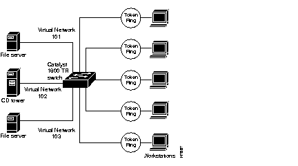
Figure E-3 is an example of a network configuration using the Catalyst 1800 switch in a virtual network configuration. In this example, five user rings connect to the Token Ring switch along with three directly attached servers. Virtual network configurations allow a user to configure multiple ports on the Catalyst 1800 switch to appear as a single logical ring with one segment number. In this example, virtual network 101 consists of two physical rings and one file server connected to multiple ports on the Catalyst 1800 switch, but is part of the same logical ring (ring 101). Traffic is most often transparently switched within a logical network. Traffic forwarded from one virtual network (ring 101) to another virtual network (ring 102) may be switched transparently or source routed depending on the frame type. The workstations and servers run transparent or source routed traffic. In this configuration, the backbone does not exist because it has been collapsed into the Token Ring switches.

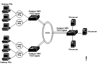
Figure E-4 is an example of a network configuration using the Catalyst 1800 switch, configured to use FDDI as the backbone. In this example, user rings connect to the Catalyst 1800 switch along with three directly-attached file servers. The FDDI ports on the Catalyst 1800 switch are used to interconnect multiple switches, creating a 100 mbs backbone. The workstations and servers run transparent or source-routed traffic.

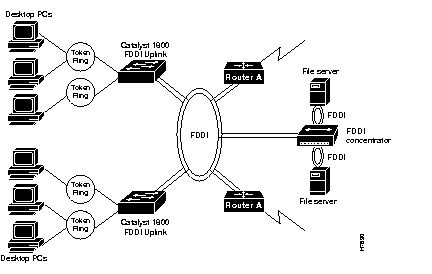
Figure E-5 is an example of a network configuration using the Catalyst 1800 switch configured to connect to an existing FDDI backbone. In this example, user rings connect to the Catalyst 1800 switch. Two file servers are connected to the FDDI concentrator. The FDDI ports on the Catalyst 1800 switch are used to interconnect to an existing FDDI backbone that consists of an FDDI concentrator and FDDI-attached routers. The workstations and servers run transparent or source-routed traffic.

|
|